|
Key Words: Gears meshing, Chainless bicycle, Shaft Drive Ansys,Design,Designmethodology,Analysis
Ashaftdrivenbicycleusesachainlessmechanismusingdrive shafts to transmit the power generated by the rider’s foot from the pedal to the rear wheel (Driving wheel) in this projectrearwheelisusedasdrivingwheel.Introductionof shaft drive took place over 100 years ago, but were very rarelyusedbecauseofavailabilityofnumberofgearratiosin chaindriveduetothepresenceofsprocketandderailleurs.
1.1 Use of Drive Shaft
Single Piece Shaft: These types of shafts find application in four wheel drive where the distance betweenaxleand engineissmall Itusesonlyasingle shaft to transmit power. The durability, quality, and strengthofthesingle piecedriveshaftisimprovedby frictionwelding.
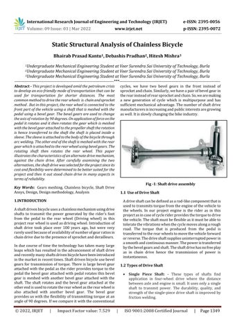
Abstract This project is developed amid the petroleum crisis to develop an eco friendly mode of transportation that can be used for transportation for shorter distances. The most common method to drive the rear wheels is chain and sprocket method . But in this project, the rear wheel is connected to the front part of the vehicle using a shaft that is meshed with the pedal using a bevel gear. The bevel gears are used to change the axis of rotation by 90 degrees. On application of force on the pedal it rotates and it then rotates the gear which is meshed with the bevel gear attached to the propeller shaft the rotation is hence transferred to the shaft the shaft is placed inside a sleeve. The sleeve is attached to the body of the bicycle through arc welding. The other end of the shaft is meshed with the rear gear which is attached to the rear wheel using bevel gears. The rotating shaft then rotates the rear wheel. This paper illustrates the characteristics of an alternate drive mechanism, against the chain drive. After carefully examining the two alternatives, the shaft drive was selected for the project since its cost and flexibility were determined to be better suited for the project and then it out stood chain drive in many aspects in terms of reliability.
Induecourseoftimethetechnologyhastakenmanylarge leapswhichhasresultedintheadvancementofshaftdrive andrecentlymanyshaftsdrivenbicyclehavebeenintroduced inthemarketinrecenttimes.Shaftdrivenbicycleusebevel gears for transmission of torque. There is large bevel gear attachedwiththepedalastheriderprovidestorquetothe pedal the bevel gearattachedwith pedal rotates thisbevel gear is meshed with another bevel gear attached with the shaft The shaft rotates and the bevel gear attached at the otherendisusedtorotatetherearwheelastherearwheelis also attached with another bevel gear. The bevel gear providesuswiththeflexibilityoftransmittingtorqueatan angleof90degrees.Ifwecompareitwiththeconventional
cycles, we have two bevel gears in the front instead of sprocketandchain.Similarly,wehaveapairofbevelgearin therearinsteadofrearsprocketandchain.So,wearemaking a new generation of cycle which is multipurpose and has sufficientmechanicaladvantage.Thenumberofshaftdrive manufacturersisincreasingandpublicinterestsaregrowing aswell.Itisslowlychangingthebikeindustry.
p
Adriveshaftcanbedefinedasarod likecomponentthatis usedtotransmitstorquefromtheengineofthevehicleto the wheels. In our project engine is the rider as in this projectasincaseofcycleriderprovidesthetorquetodrive thevehicle.Theshaftmustbeflexibleasitmustbeableto toleratethevibrationswhenthecyclemovesalongarough road. The torque that is produced from the pedal is transferredtotherearwheelstomovethevehicleforward orreverse.Thedriveshaftsuppliesuninterruptedpowerin asmoothandcontinuousmanner.Thepoweristransferred bythebevelgearsandshaft.Theshaftdrivehasnofreeplay as in chain drive hence the transmission of power is instantaneous.
| ISO
Bhairab Prasad Kantu1 , Debashis Pradhan2 , Hitesh Mishra3
Volume: 09 Issue: 03 | Mar 2022 www.irjet.net ISSN: 2395 0072 2022, IRJET Impact Factor value: 7.529 9001:2008

2Undergraduate Mechanical Engineering Student at Veer Surendra Sai University of Technology, Burla
1.INTRODUCTION
Fig 1: Shaft drive assembly
Certified Journal | Page1349
1Undergraduate Mechanical Engineering Student at Veer Surendra Sai University of Technology, Burla
1.2 Types of Drive Shaft
Static Structural Analysis of Chainless Bicycle
©
International Research Journal of Engineering and Technology (IRJET) e ISSN: 2395 0056
3Undergraduate Mechanical Engineering Student at Veer Surendra Sai University of Technology, Burla ***
p
Two or Three Piece Shaft: Theseshaftsareusedin vehiclewherethedistancebetweentheaxleandengine is large to avoid bending stress. There are some instances where number of shafts are used for gear reduction.
Fig 4: CAD of bevel gear used to mesh pedal with transmission shaft
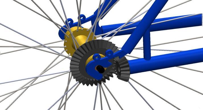
2.3. Bevel Gear
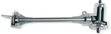
Thebasicfunctionofapedalistousetheprovideasurfaceto therider’sfoot/shoesoastofacilitatetheridertoapplyforce. The pedal harnesses the force applied by the rider. The essential component of a pedal includes a spindle which is attachedwithashaftandontheotherendthereisanother pedalwhichisat180degreesanglewiththefirstone
Certified Journal | Page1350
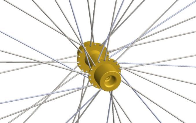
2.2. Hub
Fig -3: CAD of hub used in the project
©
Hubisthecylindricallikepartwhichisatthecenterofthe wheel.Ithasthreecomponents Axle Bearing Hubshell
A kind of gear in which the two wheels working togetherlieindifferentplanesandtheirteethcutatright anglestothesurfacesoftwoconeswhoseapicescoincide with the point where the axesof the wheelswould meet. Bevel gears are used to connect shafts whose axes lie perpendiculartoeachother,Thetoothprofileissimilarto spurgearsexceptthatthetoothgetsprogressivelysmaller asitapproachestheapexoftheprojectedcone
Pedalhasthreetypesnamely.
| Impact
Clipless
Fig 2: CAD of platform type pedal used in the project
2. COMPONENTS OF SHAFT DRIVEN BICYCLE
Bevel gears are used at two locations for two different purposes.
Clip Platform
Volume: 09 Issue: 03 | Mar 2022 www.irjet.net ISSN: 2395 0072 2022, IRJET Factor value: 7.529 9001:2008
2.1. Pedal Assembly
Connectingthepedalwiththetransmissionshaft.
Meshing the shaft with the rear wheel so as to transmit rotationalmotiontotherearwheel.
International Research Journal of Engineering and Technology (IRJET) ISSN: 2395 0056
| ISO
The hub shell typically has two circular surfaces which spokescanbeattached.Hubhelpsthewheeltorotateonthe shaft.
e
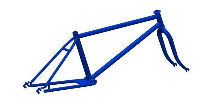
It is almost like skeleton of a body it supports the componentsofthevehicle.Themainfunctionsofaframe avehicleare:
Fig 7: CAD of frame used in our bicycle
Volume: 09 Issue: 03 | Mar 2022 www.irjet.net ISSN: 2395 0072
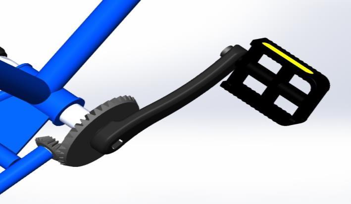
2.4 Driven Shaft
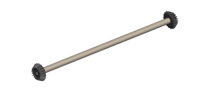
Adrivenshaftisacylindricalrodwhichisusedtotransmit torquebetweentwopoints. Ithasgearsoneitherofitsends which is used to transmit the rotary motion from the prime movertotheshaftandthenfromtheshafttothewheel.The major advantage of the shaft is instantaneous power transmissionbecauseofabsenceoffreeplayintheshaftwhich ispresentinchaindrives.
International Research Journal of Engineering and Technology (IRJET) e ISSN: 2395 0056
1. It provides support to the other component of the vehicle
A wheel is one among six simple machines. It is circular in shapeanditrotatesonanaxlehenceprovidinguswithrotary motion. The tire is connected to the hub with the help of spokes. The whole assemble of tire, hub and axle is responsiblefortheforwardmotionofthebicycle.Thereare twotiresinabicycleoneatthefrontandtheotherattherear. Thesetwotiresbearthetotalloadofthebicycleandsupport theothercomponentsofthebicycle.
Wehaveusedatubularsortofframe.
p
2. It primarily deals with distortion and deflection which arises because of dynamic loads on the Therevehicle.aremany
Fig 5: CAD of bevel gear used to mesh transmission shaft with rear wheel
types of frames which include ladder frame,Unibody.Xframe,Tubularframeetc
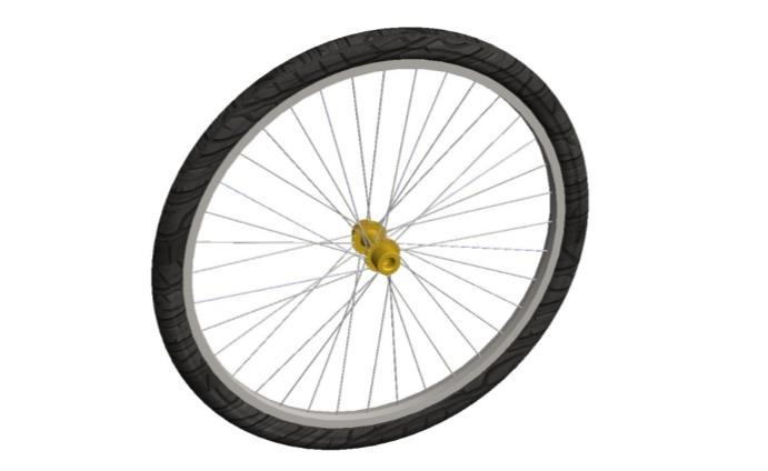
2.5 Wheel
Fig 6: Drive shaft used in our bicycle
© 2022, IRJET | Impact Factor value: 7.529 | ISO 9001:2008 Certified Journal | Page1351
2.6 Frame
Fig 6: CAD of rear wheel
●Theshaftrotatesataconstantspeedaboutitslongitudinal axis.
International Research Journal of Engineering and Technology (IRJET) e ISSN: 2395 0056
Module,m=3
No.ofteethonPinion,Zp=18
●Alldampingandnonlineareffectsareexcluded.
4.2 Design Calculation of Front and Rear Gear Set
p
Dedendum,hf=1.25*m=1.25*3=3.75mm
©
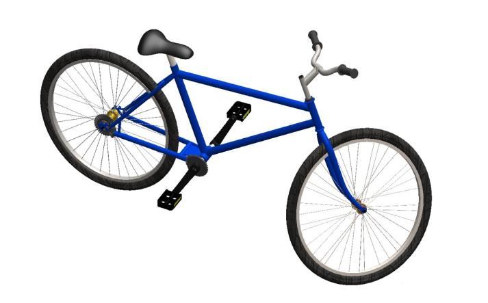
Fig 8: Isometric view of full assembly of bicycle 4.
No.ofteethonGear,Zg=36
●Theshafthasauniform,circularcrosssection.
Certified Journal | Page1352 3. FULL
(Assumemassoftherider=70kg=260.946N,g=9.81m/s²)
Torquetobetransmitted,
Lengthofthemainshaft,L=375mm
WholeDepth,h=2.25*m=2.25*3=6.75mm
●Theshaftisperfectlybalanced,i.e.,ateverycrosssection, themasscentercoincideswiththeGeometriccenter.
Polarmomentofinertia,J=π(d⁴)/2
DegreePower,P=(2πNT)/60
ConeDistance,R=D/2sin∂P=60/2sin26.560=67.09mm
Volume: 09 Issue: 03 | Mar 2022 www.irjet.net ISSN: 2395 0072 2022, IRJET Factor value: 7.529 9001:2008 ASSEMBLY OF THE BICYCLE DESIGN CALCULATION OF SHAFT DRIVEN BICYCLE
Angleoftwist,θ=TL/GJDegrees
⇒T=70*9.81*375=257512.5Nmm
Modulusofrigidity,G=41GPa
| Impact
⇒P=(2π*100*260.946)/60=2732.62W
Shearstress,τ=Tρ/J
PitchCircleDiameter,D=m*Z
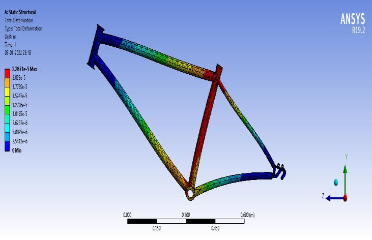
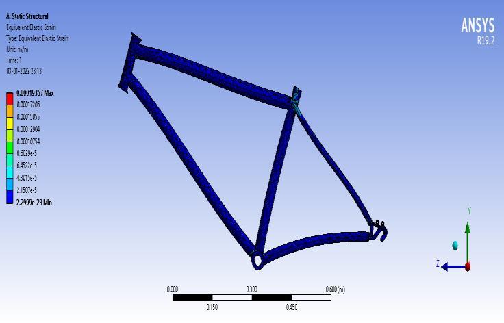
Theanalysisandsimulationareperformedonthedesigned modeloftheframeusingthesimulationtoolANSYSR19.2.It is found initially that the design is safe with respect to the givenload,basedonthetheoreticalanalysisperformed.From theStaticStructuralsimulationreportitwasfoundoutthat the design is safe. Hence, the designed shaft driven bicycle cansustaintheloadsatthepredefinedRPM.Oncomparing thetheoreticalandsimulatedvaluesit wasfoundthatthey wereapproximatelycloser.
PressureAngle,α=20°
⇒∂P=Tan 1((sin90:)/(40/20)+cos(90:)=26.56:
FaceWidth,b≤R/3=67.09/3=22.36mm Addendum,ha=m=3mm
Clearance,c=0.25*m=0.25*3=0.75mm
ToothThickness,s=1.5708*m=1.5708*3=4.71mm
FilletRadius=0.4m=1.2mm
PitchCircleDiameterofPinion,Dp=3*20=54mm
4.3 Design Calculation of Shaft
T=massoftherider*g*lengthofthemainshaft
WorkingDepth,hk=2*m=2*3=6mm
4.1. Design Assumptions
PitchCircleDiameterofGear,Dg=3*40=108mm
⇒θ=(260.946*0.380)/(41000*164895.922)=0.84:
⇒τ=(260.946*7800)/164895.922=12.343415N/mm
⇒J=π(0.018⁴)/2=164895.922mm⁴
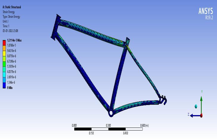
5. ANALYSIS OF FRAME OF SHAFT DRIVEN BICYCLE
Diameterofshaft,d=18mm
ConeAngle(PitchAngle)ofPinion,
ToothSpace=1.5708*m=1.5708*3=4.71mm
ConeAngle(PitchAngle)ofGear,∂G=90: ∂P=63.435:
CircleDiameterofGear,Dg=3*40=108mm
∂P=Tan 1((sin90:)/(ZG/ZP)+cos(90:)
| ISO
REFERENCES
International Research Journal of Engineering and Technology (IRJET) e ISSN: 2395 0056 Volume: 09 Issue: 03 | Mar 2022 www.irjet.net p ISSN: 2395 0072 © 2022, IRJET | Impact Factor value: 7.529 | ISO 9001:2008 Certified Journal | Page1353 Fig 9: Equivalent Stress in Static Structural Analysis of Frame Fig -10: Equivalent Elastic Strain in Static Structural Analysis of Frame Fig -11: Strain Energy in Static Structural Analysis of Frame Fig 12: Total Deformation in Static Structural Analysis of Frame
Inthisprojectwehaveaimedtoreducethewastageofenergy supplied on bicycle riding or any machine, which employs drive shafts. It is generally achieved by using light weight drive shafts with bevel gears on both sides designed on replacingchaintransmission.
Thepresented work alsodealswith optimizationofdesign i.e.,convertingrotarymotioninlinearmotionwiththehelpof bevelgearandshaftassembly
The maximum torque transmission capacity of the bicycle drive shaft has been calculated by neglecting centrifugal effects through numerical methods and has been verified through analytical methods and it was observed that centrifugalforcereducesthetorquetransmissioncapacityof the shaft. The stress distribution and the maximum deformationinthedriveshaftdependsonthewayofstacking ofmaterial.
[1] KhanHassanZakariya,KolkarAbhimanyuDashrath,Quazi Azhar Husain Farrukhzam, Shivraj Kavhale, Design and FabricationofChainlessBicycle,IRJET,Vol5Issue3.
6. CONCLUSIONS
[2] K. Gangadhar, T.R. Sydanna, M. Nagakiran, A. Salmon, Designandanalysisofshaft drivenbicycle,IJR,Vol4Issue 17
[3] K. Ganesan, K. Kavin, M. Kavin, S. K. Mathusankar, K. Nandhakumar, Design and Fabrication Of Chainless Bicycle, International Journal of Intellectual Advancements and Research in Engineering Computations,Volume 7,Issue 2
[4] Ch. Venkata Rajesh, D. Suneetha, K. Abraham, Chainless CycleUsingGearDriveMechanism,InternationalJournal ofAdvancedResearch,Volume 3,Issue 4

Bhairab Prasad Kantu,CurrentlyFinalYear Mechanical Engineering student at Veer SurendraSaiUniversityofTechnology,Burla
| ISO
[8] TriptiShrivastava,Dr.PrateshJayaswal,ChainlessBicycle System,InternationalResearchJournalOfModernization InEngineeringTechnologyAndScience,2020, Volume:2 Issue:08

Hitesh Mishra, Currently Final Year Mechanical Engineering student at Veer SurendraSaiUniversityofTechnology,Burla
[5] SurajPawar,SominathAhewad,SwapnilRandive,Ramjan Reghiwala, Sagar Mushan ,Chainless Bicycle With Ball Bearing Drive Shaft , International Research Journal of EngineeringandTechnology,Volume 7,Issue 7
Volume: 09 Issue: 03 | Mar 2022 www.irjet.net p ISSN: 2395 0072 2022, IRJET Impact Factor value: 7.529 9001:2008
Debashis Pradhan, Currently Final Year Mechanical Engineering student at Veer SurendraSaiUniversityofTechnology,Burla


[6] RGDhamak,Prof.PSNagare,Prof.AKMishra,AReview On Design Developments In Bicycle, International Advanced Research Journal in Science, Engineering and Technology,InternationalAdvancedResearchJournalin Science,EngineeringandTechnology,Volume.3,Special Issue1
©
[7] Jyoti A. Durgude, Mr.Gawade S.R., Design Development And Analysis Of Dual Mode Bicycle, International EngineeringResearchJournal(IERJ)2015,SpecialIssue2
BIOGRAPHIES
Certified Journal | Page1354
International Research Journal of Engineering and Technology (IRJET) e ISSN: 2395 0056
|