| Impact
An Efficient Wireless Power Transfer Methodology for Electric Vehicle Battery Charging
©
In this article, A classical series L C compensation methodologyisutilizedforefficientwirelesspowertransfer for EV battery charging. Theproposedmethodologyoffers constantoutputvoltage,ifinputvoltagegetvariablewithout anykindauxiliaryequipment’s.
Key Words: DC/HFAC inverter, EV battery, Wireless power transmission system, series compensation.
1PG Scholar, Dept. of Electrical Engg., S.N.D. College of Engg. & Research Center, Yeola, Maharashtra, India.
| ISO
Rushikesh Vijay Burkul1, Dr. Pawan Chandrakant Tapre2
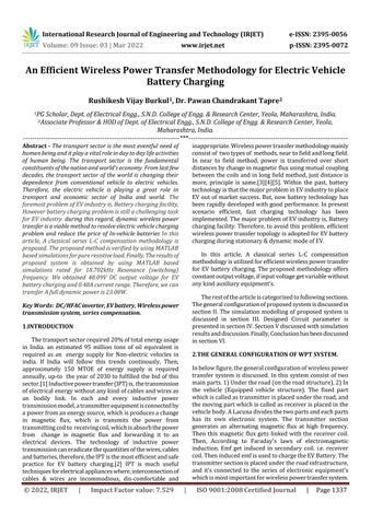
Inbelowfigure,thegeneralconfigurationofwirelesspower transfersystemisdiscussed.Inthissystemconsistoftwo mainparts.1)Undertheroad(ontheroadstructure),2)In the vehicle (Equipped vehicle structure). The fixed part whichiscalledastransmitterisplacedundertheroad,and themovingpartwhichiscalledasreceiverisplacedinthe vehiclebody.ALacunadividesthetwopartsandeachparts has its own electronic system. The transmitter section generates an alternating magnetic flux at high frequency. Then this magnetic flux gets linked with the receiver coil. Then, According to Faraday's laws of electromagnetic induction, Emf get induced in secondary coil. i.e. receiver coil.TheninducedemfisusedtochargetheEVBattery.The transmittersectionisplacedundertheroadinfrastructure, and it’s connected to the series of electronic equipment's whichismostimportantforwirelesspowertransfersystem.
Abstract The transport sector is the most eventful need of human being and it play a vital role in day to day life activities of human being. The transport sector is the fundamental constituents of the nation and world’s economy. From last few decades, the transport sector of the world is changing their dependence from conventional vehicle to electric vehicles. Therefore, the electric vehicle is playing a great role in transport and economic sector of India and world. The foremost problem of EV industry is, Battery charging facility, However battery charging problem is still a challenging task for EV industry. during this regard, dynamic wireless power transfer is a viable method to resolve electric vehicle charging problem and reduce the price of In vehicle batteries In this article, A classical series L C compensation methodology is proposed. The proposed method is verified by using MATLAB based simulations for pure resistiveload.Finally,Theresultsof proposed system is obtained by using MATLAB based simulations rated for 18.702kHz Resonance (switching) frequency. We obtained 48.09V DC output voltage for EV battery charging and 0.48A current range. Therefore, we can transfer A full dynamic power is 23.08W.
Thetransportsectorrequired20%oftotalenergyusage in India. an estimated 95 million tons of oil equivalent is required as an energy supply for Non electric vehicles in india. If India will follow this trends continously, Then, approximately 150 MTOE of energy supply is required annually,up to theyearof2030tofulfilledthebidofthis sector.[1]Inductivepowertransfer(IPT)is,thetransmission ofelectricalenergywithoutanykindofcablesandwiresas an bodily link. In each and every inductive power transmissionmodel,atransmitterequipmentisconnectedby apowerfromanenergysource,whichisproducesachange in magnetic flux, which is transmits the power from transmittingcoilto receivingcoil,whichisabsorbthepower from change in magnetic flux and forwarding it to an electrical devices. The technology of inductive power transmissioncaneradicatethequantitiesofthewires,cables andbatteries,therefore,theIPTisthemostefficientandsafe practice for EV battery charging.[2] IPT is much useful cablestechniquesforelectricalapplianceswhere,interconnectionof&wiresareincommodious,discomfortableand
2.THE GENERAL CONFIGURATION OF WPT SYSTEM.
p
Certified Journal | Page1337
2Associate Professor & HOD of Dept. of Electrical Engg., S.N.D. College of Engg. & Research Center, Yeola, Maharashtra, India. ***
International Research Journal of Engineering and Technology (IRJET) e ISSN: 2395 0056

inappropriate.Wirelesspowertransfermethodologymainly consistof twotypesof methods,neartofieldandlongfield. In near to field method, power is transferred over short distancesbychangeinmagneticfluxusingmutualcoupling betweenthecoilsandinlongfieldmethod,justdistanceis more, principle is same.[3][4][5]. Within the past, battery technologyisthatthemajorprobleminEVindustrytoplace EVoutofmarketsuccess.But,nowbatterytechnologyhas beenrapidlydevelopedwithgoodperformance.Inpresent scenario efficient, fast charging technology has been implemented.ThemajorproblemofEVindustryis,Battery chargingfacility.Therefore,toavoidthisproblem,efficient wirelesspowertransfertopologyisadoptedforEVbattery chargingduringstationary&dynamicmodeofEV.
Therestofthearticleiscategorizedtofollowingsections. Thegeneralconfigurationofproposedsystemisdiscussedin sectionII.Thesimulationmodellingofproposedsystemis discussed in section III. Designed Circuit parameter is presentedinsectionIV.SectionVdiscussedwithsimulation inresultsanddiscussion.Finally,ConclusionhasbeendiscussedsectionVI.
1.INTRODUCTION
Volume: 09 Issue: 03 | Mar 2022 www.irjet.net ISSN: 2395 0072 2022, IRJET Factor value: 7.529 9001:2008
K=M÷√L1×L2
B. Forcalculatingresonancefrequency,werequiredtwo importantparameters.
1.compensatedinductance.
GroundClearance: 170mm
Fromfig.Anominalpowerisconnectedtotheactivefront converteri.e.,AC/DCconverter, thatprovidesa DCpower supply. Then, this power supply is given to the high frequencyfull bridgeinverterwhichiscontrollingbypulse with modulation (PWM) technique, then this inverter converts input DC to high frequency AC power, which is deliver to transmitter coil. Then this magnetic flux gets linkedwiththereceivercoil.Then,AccordingtoFaraday's laws of electromagnetic induction, Emf get induced in secondarycoil.i.e.,receivercoil.Theninducedemfisusedto chargetheEVBattery
E. SelectedElectricVehiclesDetails.
Name: MahindraE2OPlus(ElectricCar).
4. CIRCUIT DESIGN PARAMETERS.
Fr=1/2π√LC.
A. The Resonance frequency is calculated by using followingequation.
M=K√L1×L2
| ISO
Certified Journal | Page1338
International Research Journal of Engineering and Technology (IRJET) e ISSN: 2395 0056
Volume: 09 Issue: 03 | Mar 2022 www.irjet.net
2.compensationcapacitance.
Therefore, we can calculate the value of compensated inductancebyusingfollowingequation.
(L)=N2Rµ0µr[ln(8R1/r) 2]
Wetookthevalueofcompensationcapacitance,accordingto selectedapplications.
L1: Self inductanceofcoil1
p ISSN: 2395 0072 2022, IRJET Impact Factor value: 7.529 9001:2008
Batterydetails: 1.Li iontype.
2.48Vvoltagerange.
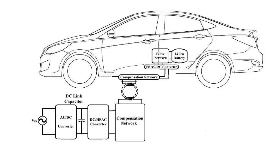
3. SIMULATION MODELLING OF WPT SYSTEM.
D. ThevalueofMutualinductanceiscalculatebyusing followingformula.
©
3.210Ahcurrentcapacity.
Batteryinstalledcapacity: 10.08Kwhr.
ElectricMotor: 3 PhaseInductionmotor,3HP
Fig -2:SimulationmodellingofproposedWPTsystem
Fig 1:GeneralconfigurationofWPTsystem.
PeakTorque: 70NM
Transmission: DirectDrive.
L2: Self inductanceofcoil2
TopSpeed: 80km/hr
M=K√L1×L2
C. Thevalueofcoefficientofcoupling(k),iscalculateby usingfollowingformula.
|
Seatingcapacity: D+4Seaters.
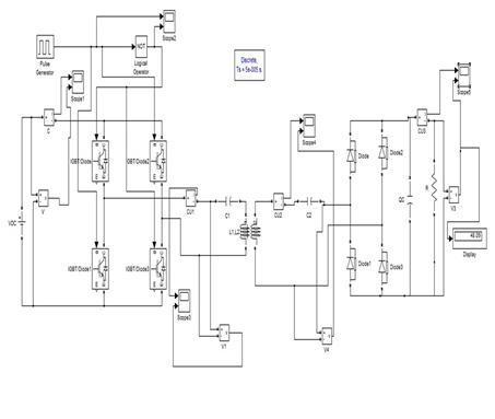
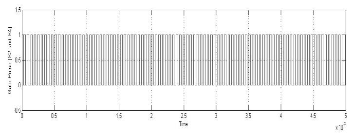
Fig.5 showsthat,whenpulseswhichisappliedbypulse generatoraregetzero,thenNOTlogicaloperatorisget invertthatpulsesandappliedthatpulsestoIGBTswitch ofHFACconverterandswitch2&4aregetturnOnInthis waytheDC/HFACconverteriscontrolbyusingsimple pulsewidthmodulationtechnique.
08 Compensationcapacitorof primarycoil C1 0.2uF
02 Resonant (Switching) frequency Fr 18.702KHZ
13 Internalresistanceofdiode RON 0.001ohm
06 Secondary coil series resistance R2 ohm0.04108
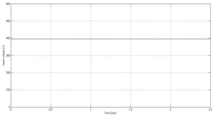
Fig.3 showsthat,theinput395VDCisappliedtohigh frequencyconverterforDC/HFACconversion.
4. RESULTS AND DISCUSSION.
01 InputDCvoltage V 395V
SYMBOL DETAILS
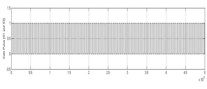
Case: 2 Gate Pulses:
© 2022, IRJET | Impact Factor value: 7.529 | ISO 9001:2008 Certified Journal | Page1339
PeakPower: 19Kw
14 Diodeforwardvoltage VF 0.8V
16 Filtercapacitance Cf 0.005F
We designed all parameters for above Electric Vehicle applications.
Primarycoilinductance L1 362.1uH
Volume: 09 Issue: 03 | Mar 2022 www.irjet.net
Theoperatingprincipleoftheproposedwirelesspower transfermethodologyisvalidatedbyperformingonMATLAB basedmodellingandsimulation.
10 Batterytype Li ion Li ion
DESIGNPARAMETERSFORMATLABSIMULATIONS.
09 Compensationcapacitorof secondarycoil C2 0.2uF
11 BatteryVoltage V 48V
p ISSN: 2395 0072
Thesimulationresultsofproposedwirelesspowertransfer system are as following. The results are divided into five casesasfollowing.
Case: 1 Input DC voltage:
05 Primary coil series resistance R1 ohm0.04108
TABLE01
15 Internal inductance of diode H 0H
PARAMETERS
17 Pulsedutycycle % 50
No.Sr.
Fig.4 showsthatthepulsesappliedtoIGBTswitchofHFAC converterfrompulsegeneratorandswitch1&3aregetturn On
07 Coefficientofcoupling Kc 0.2
03
04 Secondarycoilinductance L2 362.1uH
12 Loadresistance RL 100ohm
International Research Journal of Engineering and Technology (IRJET) e ISSN: 2395 0056
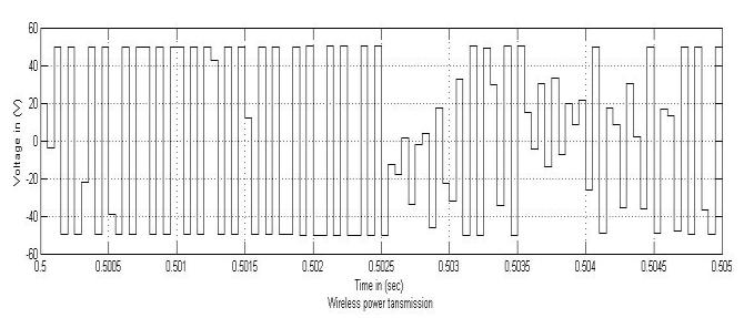
Case: 4 Wireless power transmission.
Volume: 09 Issue: 03 | Mar 2022 www.irjet.net p ISSN: 2395 0072 2022, IRJET | Impact Factor value: 7.529 | ISO 9001:2008 Certified Journal | 1340
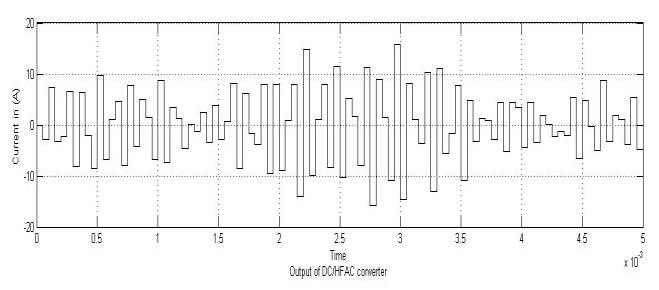
Fig.7 itindicatesthattheoutputcurrentofDC/HFAC converter.Accordingtoaboveresult,thevalueofcurrent whichiscontinuouslyvaryingduetochangeinflux linkagetothereceivingcoil.
Fig.8 itindicatesthat,thewirelesspowertransmission. In thiscase,duetomutualcouplingofcoils,changeinfluxes
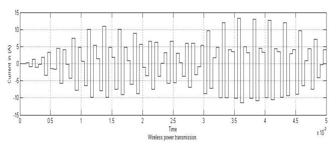
ofprimarycoilisgetlinkedtosecondarycoil.Therefore, accordingtofaraday’slawsofelectromagneticinduction, EMFgetinducedinsecondarycoil.Hence,fromabove resultweget49Vatoutput.
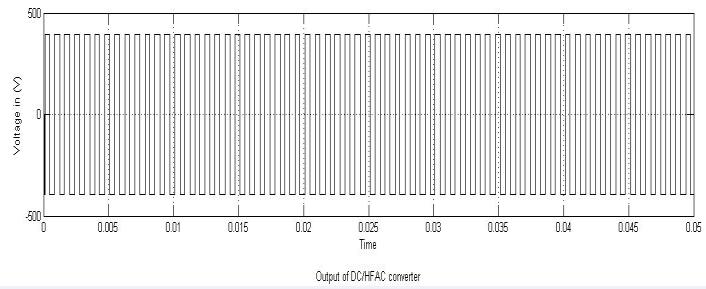
Fig.6 itindicatesthattheoutputvoltageofDC/HFAC converter.Accordingtoaboveresult,weget393VACat output.Therefore,2Vdrophasbeentakeninconversion processofIGBTswitch.
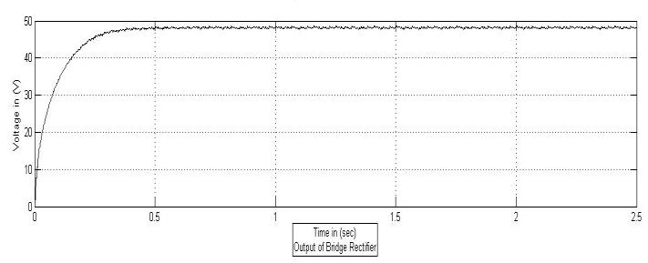
Fig.10 itindicatesthat,theoutputofbridgerectifierfor voltagequantity.Itconvertsinput49VACto48.09VDC.
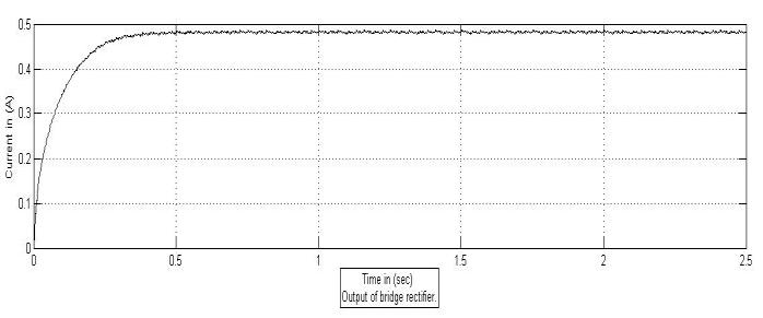
Fig.11 itindicatesthat,theoutputofbridgerectifierfor currentquantity.Therefore,weget0.48Acurrent.
Case: 3 Output of DC/HFAC Converter:
Page
©
Fig.9 itindicatesthat,thevalueofoutputcurrent.Weget 4.2Acurrentatoutputofsecondarycoil.
Case: 5 Output of Bridge Rectifier:
International Research Journal of Engineering and Technology (IRJET) e ISSN: 2395 0056
[12]Sun,Tianjia;Xie,Xiang;Wang,Zhihua(2013).Wireless powertransferformedicalmicrosystems.SpringerScience andBusinessMedia
[10]Marks,Paul (22January2014).Wirelesschargingfor electricvehicleshitstheroad.NewScientist
[16] S.B.Peterson,J.Whitacre,andJ.Apt,“Theeconomicsof usingplug inhybridelectricvehiclebatterypacksforgrid storage,”J. PowerSources,vol.195,no. 8,pp.2377 2384, [17]2010.Y.
[15]Musavi F, Eberle W. Overview of wireless power transfer technologies for electric vehicle battery charging. IETPowerElectron2014;7:60 6.
Erfani, Reza, Fatemeh, Amir M. , Mohseni, (2017) Transcutaneouscapacitivewirelesspowertransfer(C WPT) for biomedical implants.2017 IEEE International SymposiumonCircuitsandSystems(ISCAS).
[7]Miguel Poveda García, Jorge Oliva Sanchez, Ramon Sanchez Iborra,DavidCañete Rubenesque,JoseLuisGomez Tornero(2019)
[8]Bush, Stephen F. (2014).Smart grid communication enabledintelligencefortheelectricpowergrid. JohnWiley &Sons.p.
I am Thankful to My Parents and author 2 for their huge supportinmyresearch.
[9]Wireless energy transferEncyclopaedia of terms. PC MagazineZiff Davis.2014.Retrieved15December 14
In this paper, A classical series L C compensation methodology is proposed for wireless power transfer for electricvehiclebatterycharging.Wetransferefficientpower through wireless without using of any kind of auxiliary equipment's.Therefore,byusingthismethod,improvingin simplicityofstructure,operationandcontrolsystem. And also,reductioninoverallcostofthesystem.Weknowthat, hugeamountofpowerlossistakesplaceinwirelesspower transmission At inductive and capacitive load, the voltage andcurrentquantitiesarenotinphase,thereforepowerloss ismoreandwegetminimumpoweratoutput.Inthispaper, we work on pure resistive load and high resonance frequency.Therefore,weget94%ofefficiency.Inthisway, theproposedtechniqueisthebesttechniquefortheefficient wireless power transfer for electric vehicle (E.V.) battery charging.
| Page1341
[14]DaiJ,LudoisDC.CapacitivePowerTransferThrougha Conformal Bumper for Electric Vehicle Charging. IEEE J EmergSelTopPowerElectron2016;4:1015 25.
[18]Y. Jiang, L. Wang, Y. Wang, J. Liu, X. Li, and G. Ning, “Analysis,design,andimplementationofaccurateZVSangle control for EV battery charging in wireless high power transfer,”IEEETrans.Ind.Electron.,vol.66,no.5,pp.4075 4085,May2019.
[11]Lu,Yan;Ki,Wing Hung(2017).CMOSintegratedcircuit designforwirelesspowertransfer.Springer.
|
[1]OfficialWebsiteofBureauofEnergyEfficiency,Ministry ofpower,GovernmentofIndia.
5. CONCLUSION:
[5]Erfani, Reza; Marefat, Fatemeh; Sodagar, Amir M.; Mohseni,Pedram(May 18). ModelingandCharacterization ofCapacitiveElementsWithTissueasDielectricMaterialfor WirelessPoweringofNeuralImplants.IEEETransactionson NeuralSystemsandRehabilitationEngineering.
Zhou, M. Wang, H. Hao, L. Johnson, and H. Wang, “Plug inelectricvehiclemarketpenetrationandincentives: A global review,” Mitigation Adaptation Strategies Global Change,vol.No.20
©
REFERENCES
International Research Journal of Engineering and Technology (IRJET) e ISSN: 2395 0056
ACKNOWLEDGEMENT
[13]ShinY,ParkJ,KimH,WooS,ParkB,HuhS,etal.Design Considerations for Adding Series Inductors to Reduce ElectromagneticFieldInterferenceinanOver CoupledWPT System.Energies2021:14:2791.
27October2011.Retrieved16January [4]15.
[19]D. H. Tran, V. B. Vu, and W. Choi, Design of a high efficiencywirelesspowertransfersystemwithintermediate coils for the on board chargers of electric vehicles, IEEE Transaction. Power Electron., vol. 33, no. 1, pp. 175 187, Jan.2018.
p ISSN: 2395 0072 2022, IRJET Impact Factor value: 7.529 | ISO 9001:2008 Certified Journal
[6]Erfani,RezaMarefat,FatemehSodagar,AmirM.Mohseni, (July 18). Modeling and Experimental Validation of a CapacitiveLinkforWirelessPowerTransfertoBiomedical Implants.IEEETransactionsonCircuitsandSystemsII
[3]ConferenceECNMagazine.
Volume: 09 Issue: 03 | Mar 2022 www.irjet.net
[2]Ibrahim, F.N Jamail, N Othman, N.A. (2016). "Developmentofwirelesselectricitytransmissionthrough resonant coupling 4th IET Clean Energy and Technology
| Page1342
BIOGRAPHIES
©
Volume: 09 Issue: 03 | Mar 2022 www.irjet.net p ISSN: 2395 0072 2022, IRJET | Impact Factor value: 7.529 | ISO 9001:2008 Certified Journal
International Research Journal of Engineering and Technology (IRJET) e ISSN: 2395 0056
Rushikesh Vijay Burkul, has Centre,ofPowerNashik.EngineeringfromcompletedBachelorofEngineeringinElectricalEngineeringIn2019K.K.WaghInstituteofEducationResearch,Andcurrently,PursuingMasterofEngineeringinElectricalSystemfromS.N.D.CollegeEngineeringandResearchYeola,NashikMaharashtra.