Student Dept. of Mechanical Engineering, JSSATE, Noida, Uttar Pradesh, India
2
3
Worldwide, it's estimated that the domestic structures, services, and stores consume large quantity of our energy and electricity. Heating and cooling for domestic, marketable, and artificial purposes regard for a large share of total final energy demand. To lessen the burden on the active systems substantiating renewable energy into the thermal or electrical energy, a necessary first step is to apply the optimal combination of unresistant design strategies, foremost amongthemunresistantsolardesignstrategies.Geothermalenergyisconsideredarenewablesourceofenergy(noway endingsourceofenergy).Traditionalheatingandcoolingsystemneededcompressor,condenser,andevaporatorsetup. While Earth tube heat exchanger is an underground heat exchanger that can capture heat from the ground for heating purposesand dissipate heat to the ground forcooling purposes.Earth tube heat exchanger isa creative wayto use the geothermal energy to our advantage, both for heating and cooling inside the living area. Earth tube heat exchanger neededblowertomovetheairthroughoutthesetupoftheearthtubeheatexchanger.Heatisuprootedfromorrejected to the ground through a buried pipe, through fluid inflow. This simple setup helps in reducing cost, electricity consumption for the system. This system eliminates the compressor, condenser, and evaporator cost by simply using geothermalenergy.
There's an increased interest in heating and cooling system grounded on renewable energy sources. The earth air heat exchangers are suitable method against conventional systems to reduce the primary energy consumption needed for heating and cooling of structure [1]. In the system the heat pump can be used for both space heating and cooling that means the ground can be used as a source of heat in winter and as a source of cooling in summer. The energy effectiveness of the heat pump directly depends on the ground temperature. In closed circle systems, the heat pump is coupledwiththegroundsbymeansofheatexchangerthatcanbeverticallyorhorizontallyacquainted[2][3][4].Kumar et [5]al.estimatedtheconservationeventualityofanearthairpipesystemcoupledwithastructurewithno.Ghosaletal.[6] developedathermalmodeltoprobetheperformanceofearthairheatexchangerintegratedwithgreenhouse.Ajmietal. [7] studied the cooling capacity of earth air heat exchangers for domestic structures in a desert climate. Badescu [8] developed a ground heat exchanger model grounded on numerical transitional bi dimensional approach. Wu et al. [9] developed a flash and implicit model grounded on numerical heat transfer and computational fluid dynamics and also enforced it on the CFD platform, PHOENICS to estimate the effect of the operating parameters (i.e. the pipe length, compass,depthandairinflowrate)onthethermalperformanceandcoolingcapacityofearthpipesystems.Cucumoetal. [10]proposedonedimensionalflashlogicalmodeltoestimatetheperformanceofearthtoairheatex changersinstalled atdifferent depthsusedfor erectingcooling/ heating.Cuietal.[11] developeda finite elementnumerical model for the simulationofthegroundheatex changerinindispensableoperationmodesoverashorttimeperiodforgroundcoupled. Heatpumpoperations.
Volume: 09 Issue: 03 | Mar 2022 www.irjet.net
Gaurav Jain1 , Aishwarya Sen Yadav2 , Bhanu Sehrawat3, Damodar Verma4
Student Dept. of Mechanical Engineering, JSSATE, Noida, Uttar Pradesh, India
1. INTRODUCTION
Student Dept. of Mechanical Engineering, JSSATE, Noida, Uttar Pradesh, India
***
4
Abstract Now a days we all are apprehensive of the increasing price of electricity. So, everyone is moving towards sustainable living. In this case, Earth Tube Heat Exchanger is the suitable choice for the HVAC installation. In domestic structureslarge quantumof the electricity neededforheating andcoolingpurpose. Toreducetheburden on theactive systemwe'vemovedtowardsarenewablesourceofenergy.EarthTubeHeatExchangerworksonthe basicprinciplesof a heat transfer and uses geothermal energy as a source of energy. This design presents the results of theoretical computationandcomputersimulations(analysis)ofEarthTubeHeatExchanger.Bythissystem,wecanachievefulland partialHVACinstallationsinthelivingarea.AnalysisofthesystemisdonebyusingAnsysCFDanalysis.
1Assistant Professor, Dept. of Mechanical Engineering, JSSATE, Noida, Uttar Pradesh, India
Key Words: Geothermal energy, Heat Exchanger, CFD, Fluent, Effectiveness of ETHE.
International Research Journal of Engineering and Technology (IRJET) e ISSN: 2395 0056

| Impact
| ISO
Certified Journal | Page1245
p ISSN: 2395 0072 IRJET Factor value: 7.529 9001:2008
Thermal Analysis of Earth Tube Heat Exchanger
© 2022,
Thisthebasicheatenergyequationwhere,
Q = m. Cp. (T2 T1)
1.TubeMaterial whileconcludingthe tube material for ETHE wehave toconsider given parcelslike strength, corrosion resistance,durability,andcostofthematerial.
7.529 | ISO 9001:2008 Certified Journal | Page1246
e ISSN: 2395 0056
2.TubeLengthHeattransferdependsonthefacearea.
3.Thefaceareaofapipedependson:(a)Fringe (b)Length
a)Externalclimate.
4.TubeFringe
6.Thegroundtemperaturefluctuatesintime,butthebreadthofchangeloweredwithdepth.Buryingpipe/ tubes as deep as possible would be constant and become ideal. Generally, 4 5m below the earth’s face dampens the oscillationsignificantly.
d)SoilContactFactor
1 Lengthoftube=21m
5.TubeDepthGroundtemperatureaffectedbythe
Description of Numerical Method
p-ISSN: 2395-0072 Factor value:
7 ThermalconductivityofthePipe=205W/mK
8 Viscosity= 1.84×10 5 Ns/m2
© 2022, IRJET | Impact
b)SoilComposition.
International Research Journal of Engineering and Technology (IRJET)
3 Internaldiameterofthepipe=1.5m
Inthepresentstudy,transientanalysisofearthtubeheatexchangerhasbeendoneusingCFD.Earthtubeheatexchanger issimulatedtostudytheperformanceduringwinterforheatingandduringsummerforcooling.
Numericalmethodbasicallyincludesthebasicequationstosolvetheheatexchangeorflow.
So,theincreasedlengthwouldmeanraisedheattransferrateandhenceadvancedeffectiveness.After,acertainlengthno significant heat transfer occurs. Hence, optimizing the length is necessary. Adding length also results in a pressure drop. Henceincreaseaddictenergy.
2 Externaldiameterofthepipe=1.8m
Lowerfringegivesbetterthermalperformancebutresultsinlargerpressuredropsincreasedfringeresultsinareduction inairspeedandheattransfer.
5 InletTemperature=40°Celsius
c)WaterContent.
2. DESIGN PARAMETERS
www.irjet.net
6 ThermalConductivityoftheair= 0.0266W/mK
4 Velocityoftheair=(1.5,2,3,4)m/s
ThefollowingparametersaretrulyimportantindesigningofETHE.
Volume: 09 Issue: 03 | Mar 2022
It is found that by changing different parameters i.e. increasing the diameter of the pipe and air speed has the more significantimpactonthesystemCOP.
Q=Heatflow
(T2 T1)=Changeintemperature
b) Asolver
3. CFD Designing of Earth Tube Heat Exchanger
p-ISSN: 2395-0072
International Research Journal of Engineering and Technology (IRJET)
1. DesigningthemodelontheCFDplatformbyusingthegivenparameters.
CFDsoftware,FluentmainlyincludesNumericalalgorithmsandtoexaminetheresultstherearemainlythreeelementsin CFDcodesofFluent.
COPofthesystemiscalculatedas:
www.irjet.net
A grid (or mesh) of elements (or Volumes) is need to be developed, fluid properties needs to be defined, boundary conditionsneedstobeadded.Theseallaretheinputsofpre processing.Thenthesolverusesfinitecontrolvolumemethod and solve governing equations of heat and fluid flow. Then the results of those simulations are shown in the form of graphs,chartsandanimationsbypost processor.
Inthisstudyitisassumedthattheair(Flowingfluid)isin compressibleandsoiltemperatureremainsconstant.
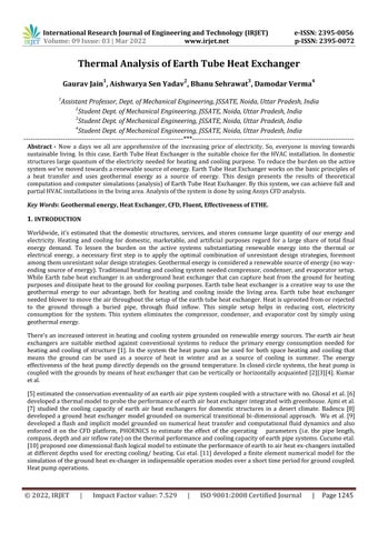
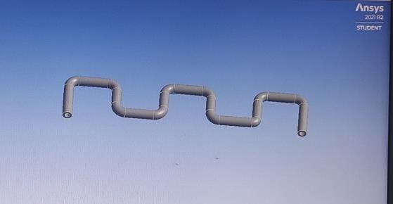
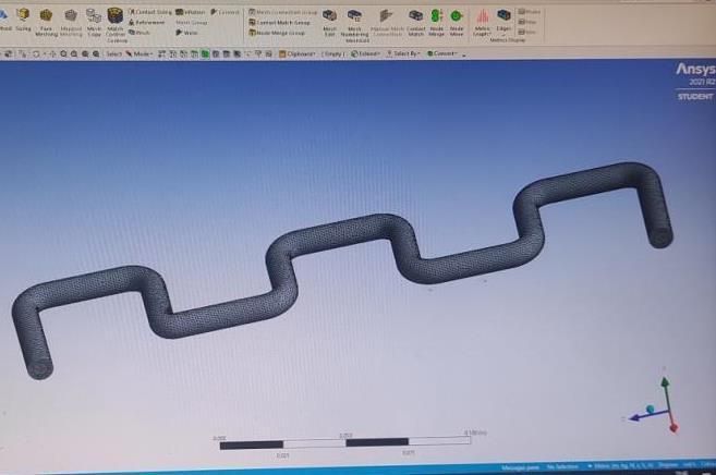
(Fig 1. Sketching)
© 2022, IRJET | Impact Factor value: 7.529 | ISO 9001:2008 Certified Journal | Page1247
Thoseelementsare:
c)Apost processor
WeneedtoLMTD(Logarithmicmeantemperaturedifference)
COP= WhereQ/WWisthesystemelectricityconsumption.
2. Firstly, selecting the appropriate material (i.e.) and then sketching the model or Geometry with appropriate dimensions.(ShowninFig1.)
e ISSN: 2395 0056
m=massofsubstance(Kg)
( )
Volume: 09 Issue: 03 | Mar 2022
Description of CFD Model
a)Apre processor
Cp =specificheatofSubstance(J/kg°C)
(Fig 3. {a}Selection Wall of the Pipe)
4. Toincreasethemeshingaccuracyforbetterresultswekeeponenhancingthegridratioandrefiningit.
© 2022, IRJET | Impact Factor value: 7.529 | ISO 9001:2008 Certified Journal | Page1248
e ISSN: 2395 0056
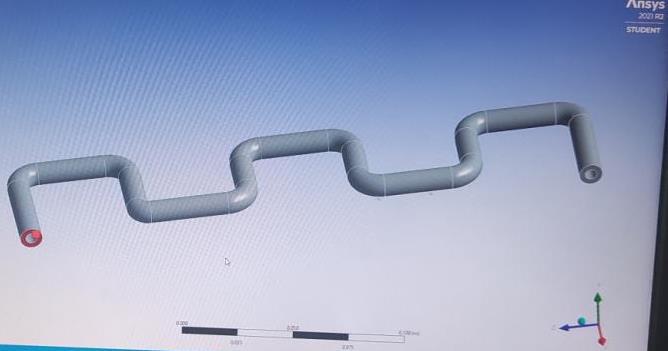
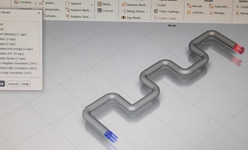
3. Thenmeshingofthemodelisdoneusingtetrahedralvolumes.Bythemethodofgridindependentsolutionswedecide thedensityofmesh.(ShowninFig2.)
Volume: 09 Issue: 03 | Mar 2022 www.irjet.net
5. ThenselectionofFacesistobedone(i.e.InletofPipe,thewall,OutletofPipeandFluiddomain). (ShowninFig3.)
(Fig 3. {b}Selection Inlet of the Pipe)
International Research Journal of Engineering and Technology (IRJET)
(Fig 2. Meshing)
p-ISSN: 2395-0072
International Research Journal of Engineering and Technology (IRJET) e ISSN: 2395 0056 Volume: 09 Issue: 03 | Mar 2022 www.irjet.net p-ISSN: 2395-0072 © 2022, IRJET | Impact Factor value: 7.529 | ISO 9001:2008 Certified Journal | Page1249 (Fig 3. {c}Selection- Outlet of the Pipe) (Fig 3. {d}Selection Fluid Domain of the Pipe) 6 ThenwesetuptheGeometrytoobservetheflowofair(fluid)inthepipe.(ShowninFig4.) (Fig 4. Set of the Model) 4. Result and Discussion Comparison of Numerical Method Output and CFD Analysis Output A Outlet Temperature of Heat Exchanger Table 1 S. No. VelocityInlet OutputMethodNumerical OutputAnalysisCFD (m/s) °CelsiusDegree °CelsiusDegree 1. 1.5 27.5 28


In the table 1, it is clearly seen there is no such variation or difference between the outlet temperature of either the NumericalmethodortheCFDanalysis.Botharenearlysame.
Engineering
B- Heat Flow and COP of the Earth Air Heat Exchanger
4.
© 2022, IRJET | Impact Factor
e ISSN: 2395 0056
7.529 | ISO 9001:2008 Certified Journal | Page1250
Here we can clearly observe that with the increase in initial velocity the value of coefficient of performance and heat outputincreasingrapidly.
2. 2 28 28.4 3 29.3 30.5 4 32 32.5
Research Journal
Volume: 09 Issue: 03 | Mar 2022 www.irjet.net p-ISSN: 2395-0072 value:
Table 2 S. No. VelocityInlet Heat Output)Method(NumericalFlow Coefficient performanceof (m/s_) (Watt) 1.5 384.795 1.5 2. 2 488.916 1.9 3. 3 642.23 2.5 4. 4 733.34 2.9

3.
International of and Technology (IRJET)
1.
The variation is clearly given in the Figure 5 below in the form of bar graph.
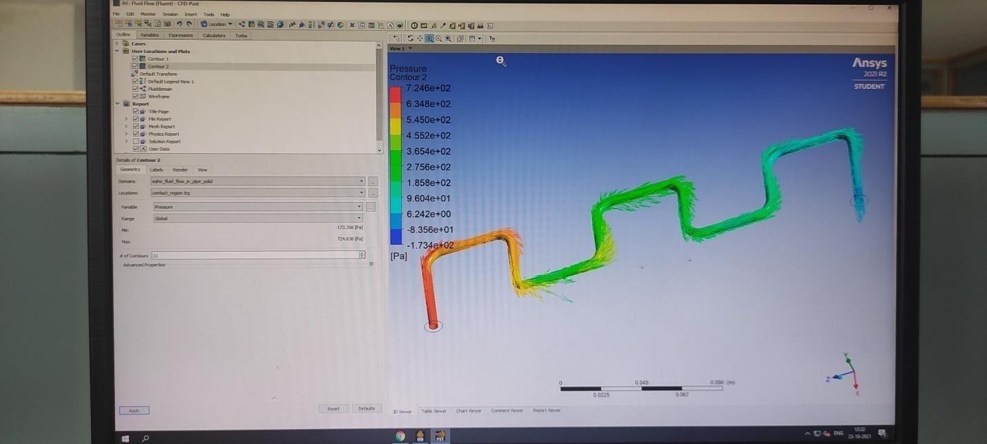
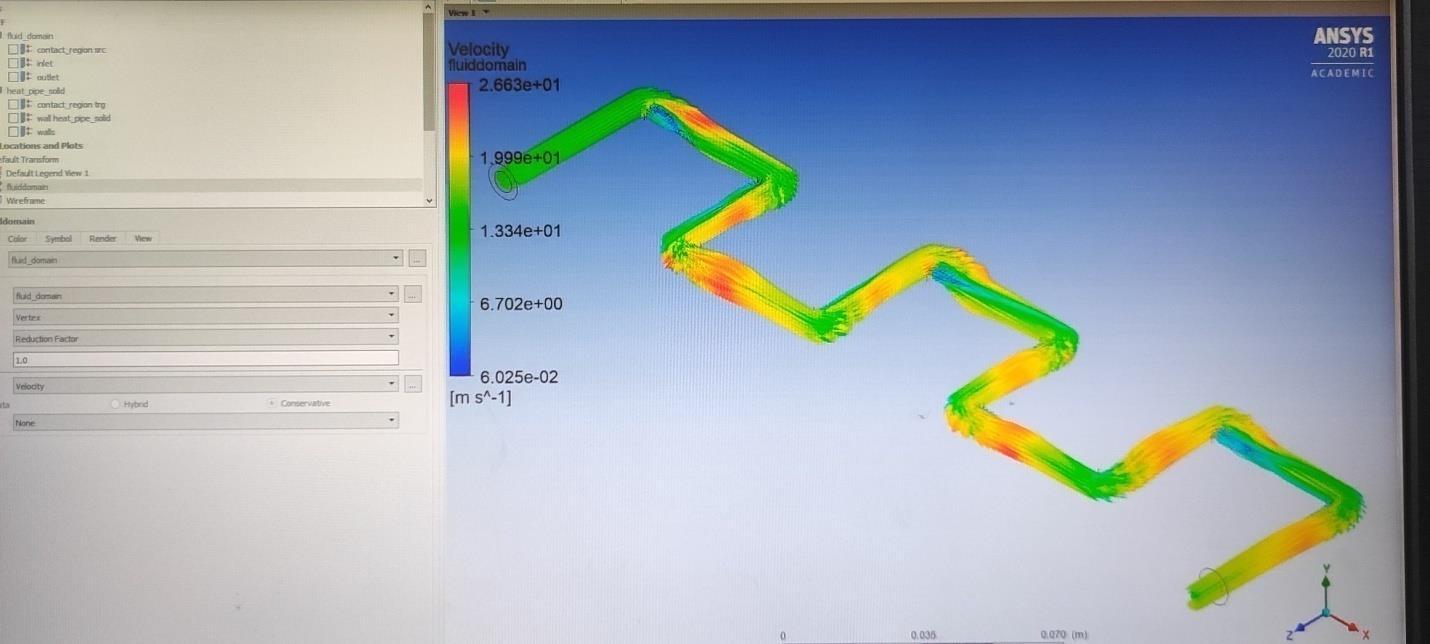
International Research Journal of Engineering and Technology (IRJET) e ISSN: 2395 0056 Volume: 09 Issue: 03 | Mar 2022 www.irjet.net p ISSN: 2395 0072 © 2022, IRJET | Impact Factor value: 7.529 | ISO 9001:2008 Certified Journal | Page1251 Simulation curves: 1 Temperature contour or Temperature Variation in the(Fig.tube.6) 2 Pressure contour or Pressure Variation in the tube. (Fig. 7)

[6]M.K.Ghosal,G.N.Tiwari,D.K.Das,K.P. Pandey,Modelingandrelative thermal performanceofgroundaircollectorand earthairheatexchangerforheatingofhothouse,EnergyandStructures37(6)(2005)613 621.
www.irjet.net p
[3] Hellström G. Ground heat storage. Thermal analysis of duct storage systems: theory. Doctoral Thesis. Department of MathematicalPhysics,UniversityofLund,Sweden;1991.
International Research Journal of Engineering and Technology (IRJET) e ISSN: 2395 0056
© 2022, IRJET | Impact Factor value: 7.529 | ISO 9001:2008 Certified Journal | Page1252
Volume: 09 Issue: 03 2022 ISSN: 2395 0072
Conclusion:
[2] Eskilson P. Thermal analysis of heat extraction boreholes. Doctoral thesis. Department of Mathematical Physics and BuildingTechnology,UniversityofLund,Sweden;1987.
[7]F.Al.Ajmi,D.L.Loveday,V.Hanby,Thecoolingeventualityofearth airheat .exchangersfordomesticstructuresinadesertclimate,BuildingandEnvironment41(2006)235 244.
| Mar
References:
It has been found that with minimum velocity of air, maximum temperature fall down is there. EAHE system is more effective when buried in more depth inside the soil and after about 4 5 meters of depth the conditions become constant andideal.Theincreaseinairvelocityincreasetheheatconvectiveheattransfercoefficientandreducethegroundcontact factor. And in these EAHE system convective heat transfer play more important role in compared to conductive heat transfer.Thepipematerialdoesnotcreateanysuchchangeexceptthesetupcost.
[5]R. Kumar,S. Ramesh,S.C. Kaushik, Performance evaluation and energy conservation eventuality of earth air lair systemcoupledwithnon air conditioned.structure,BuildingandEnvironment38(2003)807 813.
3 Fluid Domain Velocity Contour (Fig. 8)
[4]ZengH,DiaoN,FangZ.Afifiniteline sourcemodelforboreholesingeothermalheatexchangers.HeatTransfer Asian Research2002;31:558 67.
Intheabovethreefigures(6,7,8)youhaveobservedthetemperature,pressureandFluiddomainContourthathowwith time their variation is happening. From Fig. 7, it is clearly seen in at the outlet the pressure is quite less as compared to initial condition. The fluid flow or fluid domain is nearly same whole time. No such variation is there expect at corner pointsofthepipeduetosuddenchange.Thelooksofthesethreeisdifferentanditcanbesameittotallydependsonthe phaseyouareselectingin‘Solution’part,howmuchyouwanttoclearlyshowtheVariation.
[1]Shi L, Chew MYL. A review on sustainable design of renewable energy systems. Renewable and Sustainable Energy Reviews2012;16(1):192 207.
International Research Journal of Engineering and Technology (IRJET) e ISSN: 2395 0056
© 2022,
| Impact
| ISO
Volume: 09 Issue: 03 | Mar 2022 www.irjet.net
[9] H. Wu,S. Wang,D. Zhu, Modelling and evaluation of cooling capacity of earth air pipe systems, Energy Conversion andManagement48(2007)1462 1471.
[10]M.Cucumo,S.Cucumo,L.Montoro,A.Vulcano,Aone dimensionalflash logicalmodelforearth to airheatexchangers, takingintoaccountcondensationmarvelsandthermalanxietyfromtheupperfreefaceaswellasaroundtheburiedpipes, InternationalJournalofHeatandMassTransfer51 (2008)506 516.
p ISSN: 2395 0072 IRJET Factor value: 7.529 9001:2008
Certified Journal | Page1253
[8]V. Badescu, Simple and accurate model for the ground heat exchanger of a unresistant . house, Renewable Energy 32 (2007)845 855.
[11]P.Cui,H.Yang,Z.Fang, Numericalanalysisandexperimentalconfirmationofheattransferingroundheatexchangers inindispensableoperationmodes,Energyand Structures40(2008)1060 106