Volume: 09 Issue: 03 Mar 2022 ISSN: 2395 0072
Thechassisisregardedasthemostimportantcomponent ofacar.Anditisthemostimportantelementinproviding strength and stability to the vehicle under a variety of situations. The chassis, often known as the 'Frame,' is the vehicle's main support structure. It bears all of the vehicle's stresses in both static and dynamic circumstances.Everyvehiclehasachassis frame,whether it is a two wheeler, a car, or a truck. However, its shape clearlyvariesdependingonthevehicletype.Itsupportsall vehicle components such as the engine, gearbox, vehicle chassis,propellershaft,axles,tiers,fueltank,andsoon.It hascrossmemberswithvaryingcrosssectionsdepending on the vehicle type. I section, C section, and Box type crosssectionsarethemostcommoncrosssectionsusedin heavy vehicle chassis. A structural study utilizing ANSYS workbench may be used to determine the most suitable crosssectionforalargevehicle.
e
|
© 2022, IRJET | Impact Factor value: 7.529 | ISO 9001:2008 Certified Journal | Page1203
Design and Static Analysis of Heavy Vehicle Chassis with Different Alloy Materials at Different Optimum Load Conditions
1Research Scholar in Mechanical Engineering, Kakatiya Institute of Technology & Science, Warangal, Telangana, India
P.Anil Kumar2
2Assistant Professor, Mechanical Engineering, Kakatiya Institute of Technology & Science,TelanganaWarangal,,India
3Research Scholar in Mechanical Engineering, Kakatiya Institute of Technology & Science, Warangal, Telangana, India
M.Vivek4
P.Jhansi3


***
1. INTRODUCTION
www.irjet.net p
P.V.Susheel5
Key Words: Heavy vehicle chassis, static structural analysis, modelling, CATIA V5, Design, Fusion 360
5Research Scholar in Mechanical Engineering, Kakatiya Institute of Technology & Science, Warangal, Telangana, India
International (IRJET) ISSN: 2395 0056

Sravan Arimadla1
4Research Scholar in Mechanical Engineering, Kakatiya Institute of Technology & Science, Warangal, Telangana, India
Research Journal of Engineering and Technology
Abstract The chassis is one of the most important parts of an automotive. It is made up of an internal frame that is used to carry the vehicle under the stipulated conditions that it encounters throughout its operation. The supporting structure on which body of an engine and axle assembly are mounted is the backbone of any car. As a result, it is the most important component that provides strength and stability to the vehicle in a variety of settings. These chassis are mostly made of steel frames that support the body and engines of a vehicle. The term "chassis" refers to the frame or basic structure of a vehicle. The purpose of this work is to investigate the designing and statically structural analysis of a big vehicle chassis utilizing various alloy materials at various ideal loads. This heavy vehicle chassis will be designed in Fusion 360, CATIA V5, and structural analysis will be performed in Ansys workbench. The project's purpose is to build a better chassis that reduces total vehicle weight while increasing the performance of a big vehicle under ideal circumstances.
TYPESOFCHASSIS CONVENTIONAL NONCONVENTIONAL LadderFrameChassis BackboneFrameChassis MonocoqueChassis TubularFrameChassis Fig 1:ChassisTypes
p
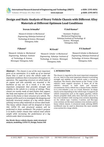
3. 3.1DESIGN:Specifications:
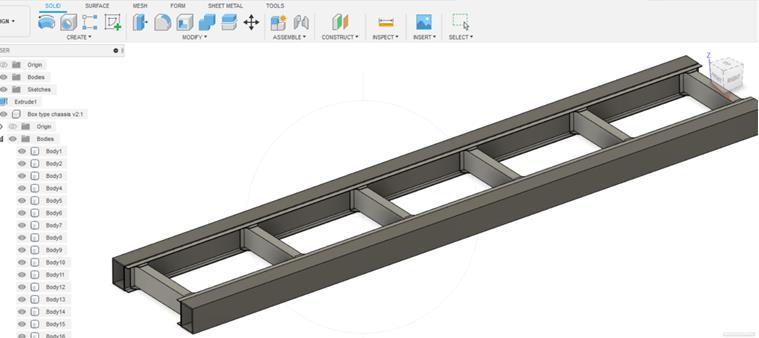
Fig 2:IsometricdrawingoftheChassis
5. Crosssectiondimensions : 210×76×6
Material& Geometry of the Truck made with C type Chassis with the following dimensions
Capacity of vehicle = 8.2tons=8200kg=79480N
a) 1. To analyze the different types of chassis and theirselectionofmaterial
1.2 Main Objectives:
d) 4.Toobservethevariedloadcircumstances.
Materialofchassis is ASTM A710 Steel
wheel base [b] = 3810 mm
Capacity ofvehicle with 1.25% = 98100.0N
a)Calculation of Reactions:
2.1 Methods used:
| ISO 9001:2008 Certified Journal | Page1204 1.1
2. METHODOLOGY AND MATERIAL SELECTION:
2.2 Selection of Material:
Steelalloysaremuchharderandstrongerthanaluminium but steel alloys are heavier in weight compared to other alloys, It isa major disadvantage for steel alloys and steel alloys are not suitable for low light vehicles. 7075 aluminumalloy(AA7075)isanaluminumalloyusingzinc as the main alloying element. It possesses exceptional mechanical properties, including high ductility, strength, toughness,andfatigueresistance.
Rear Overhang (c) = 1620.0mm
2. chassis width : 700mm
Young’s modulus, [E] = 2.15x10⁵ N/mm2

Weight of the vehicle = 2ton=2000kg=19620N
3.2 Design Calculations:
Uniformly distributed load = 58660/6345 = 9.36N/mm
Total load acting on chassis = Capacity of Chassis + Weight of body and engine = 98100+19820 = 117740N
Volume: 09 Issue: 03 | Mar 2022 www.irjet.net ISSN: 2395 0072 IRJET Factor value: 7.529 Types of Chassis:
© 2022,
Load acting on the beam = 58660N
| Impact
b) 2.Toconstructanewdesignfromanexistingone whichminimizestheoverallweightofthevehicle withexcellentloadbearingcapacity
Poisson’s Ratio = 0.287
A static analysis: Staticanalysisismostlyusedtoconduct ananalysisbyconsideringthedynamicconditionsandthis methodisusedtodeterminevariousfactorssuchasstress, deflection,strain,strainenergy,volume,weightetc.
International Research Journal of Engineering and Technology (IRJET) e ISSN: 2395 0056
1. Chassis length : 6355mm
Front Overhang (a) = 930.0mm
210mmx76mmx6mm
Beam Length = 6345mm
c) 3. To do static structural analysis using ANSYS workstation
4. Rearoverhung : 1620mm
Aluminum Alloy, Cast Iron, and Structural Steel are the materialsunderconsiderationfordesignandanalysis.The designcriteriawerechosenandinvestigatedwiththegoal of minimizing design outcomes in areas where aluminum is often used in the vehicle industry, such as chassis and body building. The using of aluminium is an advantage to reducetheoverallweightvehicle.
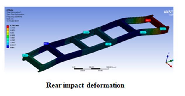
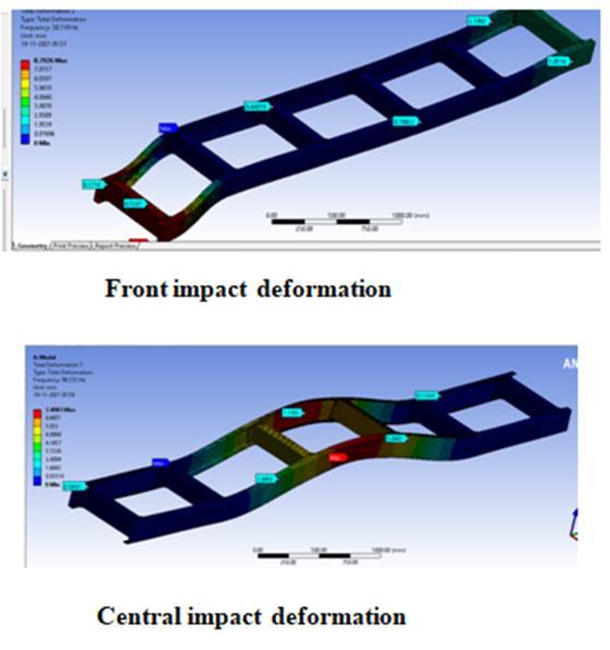
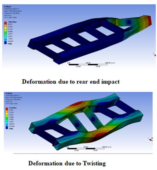
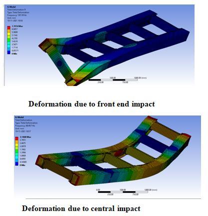
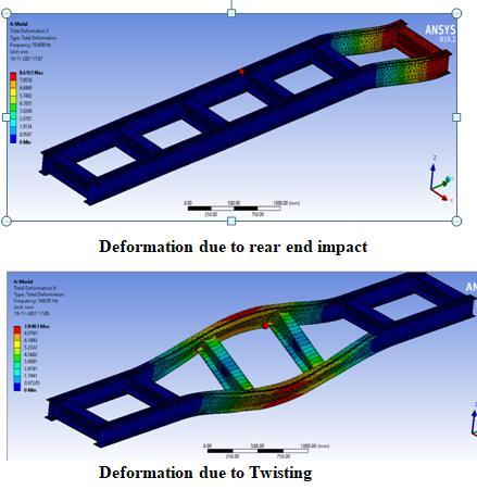
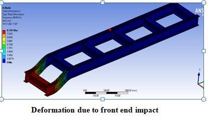
Modal Analysis: Modalanalysisistheprocessofapplying Differentloadconditionstothemodelbyfixingatdifferent locations (fixedjoints weremadeatthat place).Conditions suchasfrontendimpact,RearimpactandCentralimpact FrontendandRearendTwisting.
3. Frontoverhung : 935mm
MC =( 9.26×5×934.0)/2 = 4047661.705Nmm
b)Calculation of SF and BM: Shearforcecalculations:
R D =34757.650N
R C +R D =58857.36
BendingstressfrombendingequationM/I=fs/y=E/R Mmax =12150971Nmm
3.Usingtheextrudecommand,convertthe2Ddrawingto 4.3D.Using the material command, change the material to aluminum.
Volume: 09 Issue: 03 | Mar 2022 www.irjet.net
MD =[( 9.26×4735.0×4735.0)/2] +(24119.65×3800.0) = 12150971.075Nmm
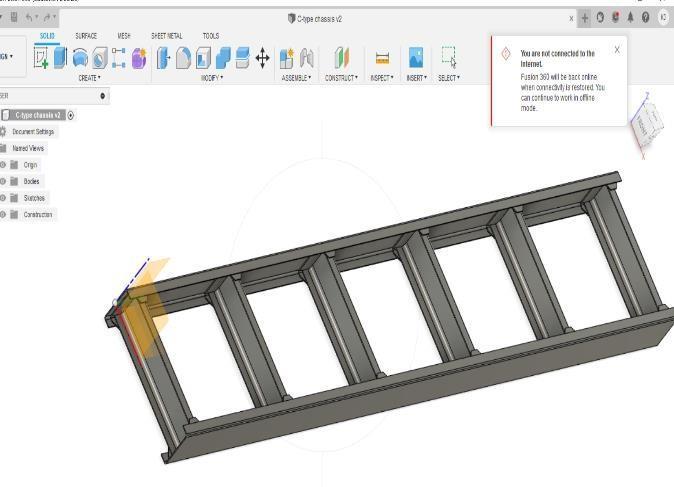
4.1 Design using Fusion360 (C-cross section):
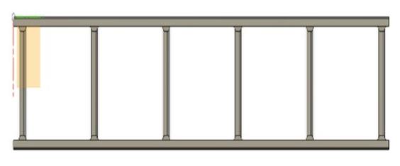
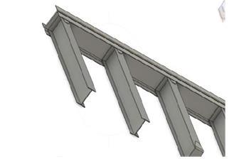
Fig 3:TopView 4: 3 DView
Fig
Total load acting on beam =9.26×6355.0 =58847.305N
M.I. aboutX Xaxis(I)=(BH3 bh3)/12=13372380mm4
4.2 Design using Fusion360 (I section):
MB =0Nmm
Journal | Page1205
FB =0N
BMcalculations:
1. Using the draw command, draw the separate parts of thepartin2D.
ShearstressfromTorsionequationT/J=τ/r=Gϴ/L Shearstressτ=482.7N/mm2
© 2022, IRJET | Impact Factor value: 7.529 | ISO 9001:2008 Certified
Consideringthe momentaboutCandthereactionload generatedatthesupportD,weobtaintheloadatreaction C& MomentD.about C 9.26×935×935/2: =(R(9.24×3800.0×3800.0/2) d×3800.0) +(9.24×1620.0×4610.0)
FA =0N
5.Assemblethecomponentpartsinthepartdrawing.
MA =0Nmm
e ISSN: 2395 0056
BendingStressfs =95N/mm2
p ISSN: 2395 0072
FC =( 9.24×936)+24200.66 =15462.66N
RC =24119.645N
c) Calculation of Shear Stress:
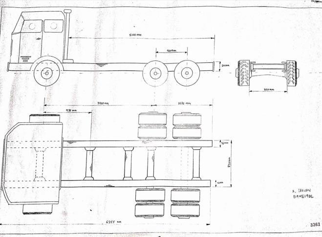
4. DESIGN AND MODELLING:
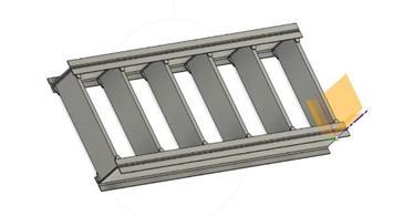
Fig 5: TopView Fig 6: SectionalView
Fusion360softwarewasusedtodesignthechassis. Fusion 360 is an interactive three dimensional application. It's a solid modeling program that combines 3D parametric features with 2D tools, as well as addressingthewholedesigntoproductionprocess.Fusion givesyoutheoptiontoseeyourdesignsin3D. Thefollowingarethestepsrequiredindesigningachassis usingFusion360:
FD =( 9.26×4735)+34727.65+2411 =115008.40N
2. Using the dimensions command to set the dimensions foreachline.
VonMisesStress=√(fs 2+3τ2)=448.5Mpa
International Research Journal of Engineering and Technology (IRJET)
Volume: ISSN: 2395 0072
Initiallytheengineeringdataissetaspertherequirement of material ,units, other properties. Then the geometry is importedintotheansysworkbench,clickoneditmodela newtabwillbeopened
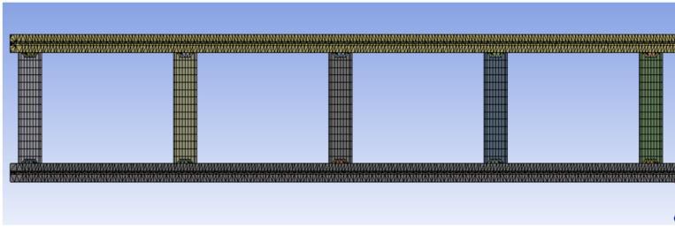
The more intricate a mesh, the more realistic the 3D CAD model,enablingforhighqualitysimulations.Meshing,also known as mesh production, is the process of creating a two dimensionalandthree dimensionalgrid.
09 Issue: 03 | Mar 2022 www.irjet.net p
Ansys 19.2 is a powerful simulation program that allows us to do a variety of analyses, including static, dynamic, fluid flow, and thermal analysis. The chassis design is saved as IGS/IGES format, which can imported into the ANSYSsoftware.
c)
d)
f)
5.2 Meshing and Load setup:
International Research Journal of Engineering and Technology (IRJET) e ISSN: 2395 0056
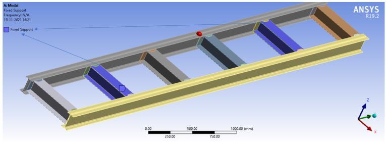
The meshing is done on a 3516 node model with 180282 cubical and tetrahedral components. The static forces from the truckbody and the load on the truck chassis model Forthiskind,the maxloadedweightofthevehicle +bodyis12,000kg.Theloadisexpectedtobedistributed evenly,withthemaxloadedweightdivided by thewhole length of the chassis frame. A finite element model with boundaryconditionsrepresentsthechassis.
5.3 Static Analysis of Chassis using ANSYS:
5.1 Steps involved in Static Analysis: Engineeringdata GeometrySetting Modelimporting Meshingpart Analysispart Resultsobtained
5. ANALYSIS USING ANSYS WORKBENCH:
Fig 12: BoundaryConditions
e)
a)
Fig 11: Meshing
b)
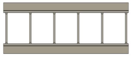
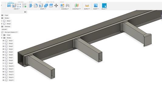
© 2022, IRJET | Impact Factor value: 7.529 | ISO 9001:2008 Certified Journal | Page1206 Fig 7: 3 DView 4.3 Design using Fusion360 (Rectangular Section): Fig 8: TopView Fig 9: SectionalView Fig 10: 3 DView
International Research Journal of Engineering and Technology (IRJET) e ISSN: 2395 0056 Volume: 09 Issue: 03 | Mar 2022 www.irjet.net p ISSN: 2395 0072 © 2022, IRJET | Impact Factor value: 7.529 | ISO 9001:2008 Certified Journal | Page1207 5.6 ANSYS Results of C section Chassis 5.4 ANSYS results of I-Section Chassis 5.5 ANSYS Results of Rectangular cross section


International Technology (IRJET) ISSN: 2395 0056
Aluminium alloy 6064 T6 56 6.1 7.2
e
© 2022, IRJET | Impact Factor value: 7.529 | ISO 9001:2008 Certified Journal | Page1208 6. RESULTS: 6.1 Results for I Section Chassis 6.2 Results for rectangular section Chassis 6.3 Results for C Section Chassis 6.4 ANSYS Results for I Section Chassis 6.5 ANSYS
Material Von(Mpa)StressMises Max. StressShear(Mpa) Deformation(mm)
In this work, the ANSYS 20.1 software was utilized to assess a ladder type chassis construction for a vehicle. According to the research, the C section is stronger than the Rectangular and I Cross section varieties of Ladder Chassis. For Aluminum Alloy 6063 T6, the C Cross section Ladder Chassis has the least deflection, 2.96 mm, as well as the lowest Von Mises stress and Maximum Shear stress, 54.31MPa and 5.98MPa, respectively. Finite element analysis is a strong technique for tackling the conceptionandformulationstagesofdesign.Basedonthe present work's analytical results, the following conclusionsmaybedrawn.
b) Theshapehasbeenadjustedtoallowstresslevels to be dropped slightly below the yield limit in ordertoenhanceperformance.
p
for Rectangular Section
Astm A302 alloy steel 59.6 11 3.5
Research Journal of Engineering and
ASTMA302alloy steel 335 190.75 2.57 aluminiumalloy 6063 T6 168 92.75 7.9
| Mar
Volume: 09 Issue: 03 2022 www.irjet.net ISSN: 2395 0072 Results Chassis ANSYS Results for C-Section
Astm A710 steel 70 15 2.1
ASTMA710steel 434 250 2.064
ASTM A710 steel 430 242 2.36
Material Von(stressmisesMpa) ShearMaximumstress(Mpa) Deformationmm
6.6
ASTM a302 alloy steel 140 71 9.3
Chassis
Aluminumalloy 6063 T6 158 84 6.35
7. CONCLUSIONS
a) The component is safe under the given loading conditions.
f) The Rectangle Cross section Kind of Chassis has the lowest deflection, Von Mises stress, and Greatest Shear stress for Aluminium alloy 6063 T6 in all three materials among three distinct cross section kinds of Ladder Chassis.
ASTM a710 steel 150 78 6.8
d) Shear stresses were determined to be lowest in aluminum alloy 6063 T6 and largest in ASTM A710steelatdefinedboundaryconditions.
ASTMA302alloy steel 326 185 2.6 aluminiumalloy 6063 T6 166 90 7.2
c) The Von Mises Stress and Maximum Shear Stress produced are less than permitted value, demonstrating that the design is safe for all threematerials.
material Vonstressmises(Mpa) ShearMaximumstress(MPa) Deformationmm
ASTMA302alloy steel 328 188.5 2.015
ASTMA710steel 160 88 7.4
e) Von Mises stresses were determined to be lowestin aluminum alloy 6063 T6 and largest in ASTM A710 steel at defined boundary conditions.
ASTMA302alloy Steel 154 81 10.2 Aluminumalloy 6063 T6 141 76 14.6
Material Vonstressmises(Mpa) ShearMaximumstress(MPa) Deformation(mm)
Aluminiumalloy 6063 T6 112 63 14.6
ASTM A710 steel 440 252.3 2.84
material Von(stressmisesMpa) ShearMaximumstress(Mpa) Deformationmm
material Von(Mpa)StressMises Max. StressShear(Mpa) Deformation(mm)
[5] Mooli Harish and K. Bhaskar, "Modeling And Analysis Of A Heavy Vehicle Chassis Using Composites E Glass Resin & S 2 Glass", ISSN: 2177 3868, Volume 7, Issue 6, March2019.
© 2022, IRJET | Impact Factor value: 7.529 | ISO 9001:2008 Certified Journal | Page1209
International Research Journal of Engineering and Technology (IRJET) e ISSN: 2395 0056
P.Anil Kumar is a mechanical engineering Ph.D scholar at Sathyabama Institute of Science and Technology in Chennai. CFD, Automobile, FEA, ToM, and Fracture Mechanics are among his research interests. He has more than two research articles published in international journals/conference

8. REFERENCES


[3] Wang Gouging, Leo Shaun, and Zeng yahoo, "Finite Element Analysis on the Chassis of a Tracked Test Vehicle,"ISSN:7695 4639,Issue:10 11 2012.
P.V.Susheel is a a mechanical student at kaktiya institute of technology & science, warangal.


M.Vivek is a mechanical engineering student atKakatiya Institute of technology & science, warangal.
9. AUTHOR BIOGRAPHIES
[1] A. Hari Kumar & V. Daryanani, "Design & Analysis of Automotive vehicle Chassis," International Journal of Engineering Science and Technology, volume. 5, number. 1,January2016,ISSN:2319 5967.
P.Jhansi is a mechanicalengineering student at Kakatiya Institute of Technology and ScienceinWarangal.

[2] Xiong Xin, Chen Menghuna, “The Investigation of AutomobileChassisDesignandDevelopmentUsingDigital Mock Ups”, IEEE Issue:05 march 2011
[4]AbdulkadirYasarandAliBirkin,"Design,Analysis,and Optimization of Heavy Vehicle Chassis Using FiniteElementAnalysis,"InternationalJournalofScientific and Technological Research, Vol 1, No. 6, 2015. ISSN: 2422 8702.
Volume: 09 Issue: 03 | Mar 2022 www.irjet.net p ISSN: 2395 0072
A.Sravan isamechanicalengineeringstudent at Kakatiya Institute of Technology and Science in Warangal. His research interests include design and robotics. He has one researcharticle published in an international journal/conference.