p
In this research, theoretical and experimental characterization of the braking distances using conventional braking system, ABS, emergency braking systems are evaluated at different vehicle loads and speeds. The theoretical models are performed using Matlab Simulink, while the experimental works are done using a quarter car model, which is designed, manufactured,andbuiltintheLab.
Atconstantload,Dsisdecreasedby14%whentheapplied force is increased by 20%. At a vehicle speed of 100 km/hr, Ds is increased by 25% when its load varied from noloadtofullload.Dsisdecreasedabout12.5% bywhen thecoefficientoffrictionisincreasedby10%.UsingABSat 100km/hrandfullload,Dsisdecreasedabout35%,while using EBS with ABS at full load, Ds can be reduced about 25%comparingwiththeABSalone.
Driving a vehicle is not a challenge but to ensure safe driving is an issue. Therefore, car manufacturers and institutions are working to improve the safety on roads. Safe driving includes passive and active systems. Passive systems minimize passenger injury during a crash (seat belts, neck sup port etc.) where as active systems prevent crashsuchasantilockbrakingsystem(ABS)[1].
The braking in emergency situation in conventional vehicles causes the wheels to lock. This locking of brake reduces the friction between tires and road, as a result
All these factors affect braking distance to a greater or lesser extent depending on the actual conditions when decelerating. A general method for determining braking distanceatdifferentspeeds,whichisrepresentativeforthe composition of cars, drivers and friction, requires knowledge of the significance of the individual factors for overall braking distance. The purpose of this study is to assess the braking behavior of nonprofessional drivers, including braking distances under different physical conditions [3]. The automatic braking is a technology for automobiles to sense an imminent collision with another vehicle,personorobstacleandtoapplybrakestoslowthe vehiclewithoutanydriverinput.Sensorsareusedtodetect other vehicles or obstacles, these can be radar, video, infrared,laser,ultrasonicorothersensingtechnologies[4].
Volume: 09 Issue: 03 | Mar 2022 www.irjet.net ISSN: 2395 0072 2022, IRJET Impact Factor value: 7.529 9001:2008

|
©
2Researcher, Sehafa Technological College, El Sehafa, Cairo, Egypt
1. INTRODUCTION
1.1 Disc Brake
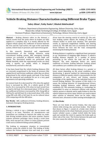
There are two kinds of service brakes, that stop your vehicle while driving: disc and drum brakes. Disc brakes that shown in Figure 1 consist of; a brake rotor which is attacheddirectlytothewheel.Hydraulicpressurefromthe master cylinder causes a caliper (which holds the brake pads just outside the rotor) to squeeze the brake pads on eithersideoftherotor.Thefrictionbetweenthepadsand therotorcausesthevehicletoslowandstop.
It has been found that the vehicle braking distances (Ds) are inversely proportional to the brake oil pressure (the appliedforce)andfrictioncoefficient,whiletheyaredirect proportional to the vehicle speeds and loads. It has found that the measured and predicted Ds are in a very good agreementatalloperatingconditions.
1Professor, Department of Automotive Engineering, Helwan University, Cairo, Egypt
International Research Journal of Engineering and Technology (IRJET) e ISSN: 2395 0056
| ISO
Key Words: ABS, coefficient of friction, braking distance, AutomaticEmergencyBrakingSystem.
Brakingdistanceisappliedasasignificantbasicparameter in e.g. calculations of stopping sight distance. A vehicle’s braking distance depends on a number of factors pertaining to the vehicle, the road and the driver’s behavior. The most important factors are; speed, coefficient of friction, braking behavior, braking system andcondition,tyreconditionandroad’sverticalgrade.
Abstract Braking distance refers to the distance a vehicle travels from the point where its brakes are fully applied to a complete stop. It is mainly affected by the original vehicle speed, the coefficient of friction between the tires and the road surface, the type of the used brake system,vehicleload,irepressure,androadverticalgrade.
3Assistant Professor, Department of Automotive Technology, Helwan University, Cairo, Egypt ***
driver loses the steering control of vehicle [2]. The anti lock braking system detects the locking of wheel and releases brakes to avoid such situation. This operation results in improved longitudinal stability and steering control [3]. The ABS also tries to maximize the frictional forces between the tires and the road, consequently minimizingthebrakingdistance.
Vehicle Braking Distance Characterization using Different Brake Types
Sabry Allam1, Fathy Nader2, Khaled Abdelwahed3
Certified Journal | Page1096
International Research Journal of Engineering and Technology (IRJET) e ISSN: 2395 0056
p
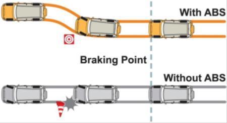
Anantilocksystemcanattainmaximumfictionalforceand results minimum stopping distance. This objective of antilock systems however, is tempered by the need for vehiclestabilityandsteerability.StabilityThefundamental purpose of braking systemic to decelerating and stopping of the vehicle, maximum friction force may not be described in some cases like asphalt and ice (p split) surface, such that significantly more braking force is obtainableononesideofthevehiclethanontheotherside. Sowhenapplyingafull brakeonboththesideswill result in a yaw or skidding moment that will tend to pull the vehicle to the high friction side and results in vehicle instability.Herecomestheconceptofantilock systemthat maintains the slip both rear wheels at the same level and minimizetwofrictioncoefficientpeaks,thenlateralforceis reasonably high thought not maximized. This contributes tostabilityandanobjectiveofantilocksystems[7].Figure (4)showseffectofAnti lockBrakingSystem.
ABS (Anti lock Braking System) is a braking system that ensuresfullcontrolofthesteeringwheelbypreventingthe vehicle from locking the wheels in sudden braking situations in all road conditions and at all speeds. ABS systemisdevelopedtopreventthelockingofthewheelson motorlandvehicles.InthecaseofABSbraking,thechange inthenumberofrevolutionsofeachwheeliscontrolledby
| Impact
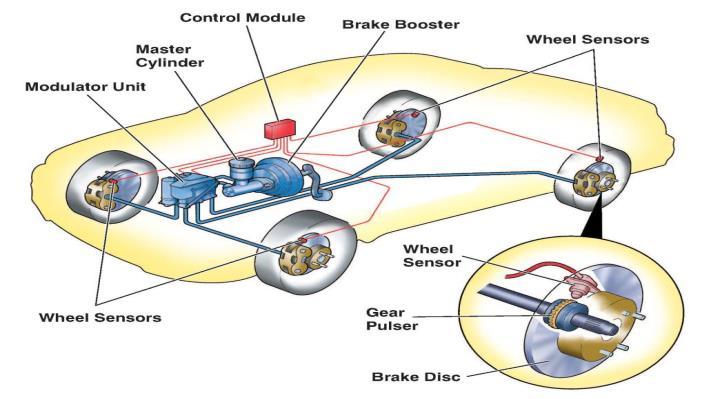
Figure(3)Locationofwheelspeedsensors,master cylinder,controlmoduleinthevehicle[8]
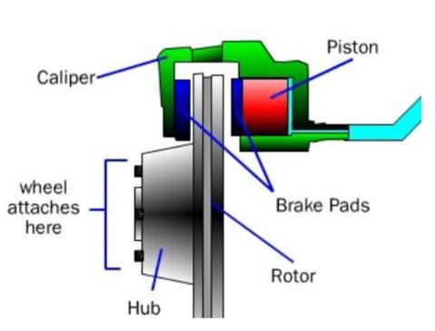
The reactive force shifts the caliper housing and presses theotherbrakepadagainsttherotor.Figure(2)showsthe ideaofoperationoffloatingtypediscbrake,thebrakefluid pushes the piston to the leftwhen the brake isapplied,so the piston pushes the inner pad and presses it against the disk,theslidingcaliperhousing reactsbyshiftingtowards right pushing the left pad against the disc, in order to generateafrictionaltorquetosloworstoptherotor.
1.2 Anti lock braking system
Thedisc brakesystemsareclassified as;floatingandfixed caliper. A floating caliper type is shown in figure (2). This typeofbrakeusesonlyasinglepistontosqueezethebrake padagainsttherotor[6].
©
Certified Journal | Page1097
an electronic control unit which is called Brake Control Module(BCMorEBCM).ABSisasystemthatdoesnotlose theconnectionofthewheelswiththesteeringwheelwhen thebrakepedalispressed.Itstopsthewheelsbysendinga commandtothewheelswithveryshortintervals,andafter averyshorttimeitsendsthecommandagaintodeactivate squeezed brake calipers. This sequence state is repeated twenty times in a second. The aim is; when a car at high speed it cannot suddenly stops, it cannot stay where it is due to moment of inertia. So, it continues to slide forward suddenly. At this time, passengers inside the vehicle can even jump out of the windshield. However, ABS slows the wheels and stops the car in a controlled way. Figure (2) shows Location of wheel speed sensors, Master Cylinder, Controlmoduleinthevehicle[8].
| ISO
Figure(2)Floatingcaliperdiscbrake[7].
Volume: 09 Issue: 03 | Mar 2022 www.irjet.net ISSN: 2395 0072 2022, IRJET Factor value: 7.529 9001:2008
Figure(1)Discbrakesystem[6].
The braking force is generated by piston squeezing frictional material in both sides of the rotor/disc which is attached to the wheel. The U shaped caliper is supported by stationary vehicle components such as the suspension system[5,6].
1.3 Automatic Braking System
Volume: 09 Issue: 03 | Mar 2022 www.irjet.net ISSN: 2395 0072 2022, IRJET Factor value: 7.529 9001:2008
p
The results advised that several of those accidents were caused by basic cognitive process. Automatic braking system mix sensors technology with brake system to forestall high speed impact and number of the automated braking systems will stop collisions altogether however most of them are designed and placed for the luxurious high price vehicles. Since high cost vehicles are additional doubtless to be fatal than affordable automatic braking systems will save lives and scale back the number of property harm that happens throughout an accident in traditional vehicles. a number of these systems use lasers othersuseradiodetectionandrangingandafewevenuse video information. The IR detector input is employed to work out if there is any objects gift within the path of the vehicle. The IR detector is placed before bumper; the system will then confirm the speed of the vehicle islarger than the speed of the thing before of it. A big speed of the vehicle could indicate that a collision is probably going to occur during which case the system is capable of
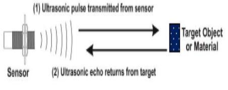
had an intense study to develop a new system. where driver may not applythe brake but the vehicle will able to stop or divert automatically due to obstacles. For the safety purpose and to avoid such unconditional accidents an automatic control braking system is introducing in the vehicles. Here a ranging sensor is used i.e. ultrasonic sensor which detect through the ultrasonic wave. Whenever a hindrance is recognized by the sensor, theultrasonicsensordetectsandreflectbacktodivertthe route of the vehicles. In this study the vehicles will automaticallydivertandapplybrakeduetoobstaclewhen the sensor senses the obstacle as shown in Figure (5). In this system an automatic braking and diverting system is designed in which the car will automatically reflect after received signal from the sensor [00]. In this study, ultrasonic sensor is used to model the automatic braking system. It enables to move the vehicle with less human drivingfocus.Theinterferenceisdetectedbytheultrasonic sensor. The servo motor functions as an actuator to processthefeedbackfromtheultrasonic.
| Impact
Automaticbrakingsystemusesaninfra redtechnologyina largesortofwirelessapplicationsandthemostoftheareas such as sensing and remote control system. The electromagneticspectrumistheinfraredportionisspitted into three regions and they are close IR region, far IR region and middle IR regions. The wavelength of the regionsandtheirapplicationsaregiven.Thecloseinfrared region is 700 nm to 1400nm, fiber optic middle infrared sensoris1400 3000nmandheatsensinginfraredregionis 3000nm to millimeter. For optical sensing and optical communication,iconopticstechnologiesareutilizedinthe close to infrared region because the light weight is a smaller amount complicated than RF once enforced as a supplyofsignal.Opticalwirelesscommunicationisfinished with IR information transmission for brief vary applications. The emergency braking system combination andwithdriverassistantsystemareusedtoslowdownthe automobile vehicle and potential warning before the collision. The research deals with the implementing of emergencybrakingusingautotropic[8].
Figure(4)EffectofABS[8]
2. LITERATURE REVIEW
mechanically activating the brakes. The signal from the IR detector that is connected to the stepper motor through controlunitwhichcreatethebrakingsystemtomanageat this example. The speed detector senses the speed of the vehicle and stepper motor is activated depends on the speed of the vehicle. The braking is activated by programmed within the management unit. The stepper motor that drags the braking cable which is connected to the front and rear wheels at variable force. However, automaticbrakeswillsaveyourlifeifyoueversufferfrom a short lapse in concentration. The idea of this project is price effective and might be used these in rider vehicle [01
©
| ISO
M Watany[01]presentedamathematicalsimulationofan ABS in MATLAB, which employs a quarter car vehicle's model undergoing a straight line braking maneuver. The model also incorporatesa hydraulic brake valve dynamics and road tire interaction. The road tire interaction model is given in the form of an empirical function (Magic
International Research Journal of Engineering and Technology (IRJET) e ISSN: 2395 0056
Figure(5)AschematicdiagramofUltrasoundworking principlesinautomaticbraking[11].
The].work
Certified Journal | Page1098
|
p ISSN: 2395 0072 2022, IRJET Impact Factor value: 7.529 9001:2008 Certified
Shival D. [11] has designed and Development of Vehicle Anti collision System using Electromagnet and Ultrasonic Sensors. The electromagnetic anti collision device was Designed in order to avoid Vehicular Head to Head/Back collision that estimates the distance between the two vehicles running extreme traffic condition. An ultrasonic sensorusedtofindtherangdistancebetweentwovehicles moving and sends it to the ECU (electronic control unit) usingtheseinputsifitfindsthevehicleinthevicinityofthe other it will automatically actuate the sensor strip for Electromagnetic Induction. A microcontroller (ATMEGA 16) responsible for received signals echo from the ultrasonicrangefindingthesensor.
Zhang, Lu [05] has designed technology of an Automatic BrakingSystemintheReversingBasedonElectricVacuum Booster. This system can avoid the collisions in the reserving and keep the vehicle in low uniform speed. This system is mainly involved in four major modules, the detecting module, MCU module, braking control module, and display module. He used the fuzzy PI controller to maintainthevehiclespeedbyEVB.Ifthereal timedistance is in the dangerous range, the vehicle will immediately stop.Inthissystem,ultrasonicsensorsareusedtomeasure distance. The result of the experiment shows the success rateisupto95%.Theprocessofvehiclebrakingistraveled between 0.15m and 0.25m. Advantages of this system, displaysofreal timespeed,real timeacceleration.
Jeyanthi R [06] has presented an advanced automatic brakingsystemwithsensorfusionconcept.Thistechnique allows for both detection and classification of objects. An ultrasonicsensorisusedtomeasurethedistancebetween vehicle and obstacle and, the capacitive sensor is used for classification of objects. The result shows he placed the systeminacarwhosebrakingsystemiscontrolledbyaDC motor.Hehastestedtheworkingofthesysteminathree speed level operation specified above. The system responded by reducing the speed of the vehicle when the obstacle is placed at a variable distance from it. Also, the system disabled horn automatically and reduced speed automaticallyinrestrictedareas.
©
T.U. An and Santhosh K. [10] presented an advanced accident avoidance system for automobiles. The complete
Firoz S. [08] presented an intelligent mechatronic braking system. The main target for this presented technology is, cars can run automatic braking due to obstacles when the sensorsensestheobstacles.Thebrakingcircuitfunctionis to break the car automatically after the received signal from the sensor. An intelligent mechatronic system includes an ultrasonic wave emitter provided on the front portion of a car producing and emitting ultrasonic waves frontwardinapredetermineddistance.Thereflectedwave (detected pulse) measured the distance between the obstacle and the vehicle. Then a microcontroller (ATMEGA32)isusedtocontrolthespeedofthevehicle.
The ultrasonic vehicle braking system involves an in front component of an automatic braking vehicle with an ultrasonic sensor generating and emitting the front of the ultrasonicwaveatacertaindistanceinfrontofthevehicle was presented in [02]. Ultrasonic beneficiary likewise molded a vehicle's front area, getting an intelligent ultrasonic wave signal as an impression of the hindrance situated inside the separation determined. The wave was estimated to acquire the separation between the vehicles andtheobstructions.Ontheotherhand,Arduinoisutilized to drive the servo engine based on location data to constrain the brake pedal to irregularly brake the vehicle toconsequentlybrakethevehicleforsafebraking.
Journal | Page1099
Volume: 09 Issue: 03 | Mar 2022 www.irjet.net
formula) describing the nonlinear relation between adhesion (rolling) coefficient and wheel slip. A Bang Bang controllerhasbeenimplementedwiththeabovemodelfor controllingwheelslipatgivendesiredreferencevalue.The brakingperformancesinbothassistedABSmodeandnon ABS mode have been evaluated by simulation. Simulated results of stopping distances were confirmed using a road test setup. The results indicate that the braking performance of automotive assisted ABS was improved significantly, the braking time advanced, and the stopping distance shorten consequently, the braking safety of vehiclecanbeimproved.
VidyadharM.[07]presentedasystemthatcanenhancethe safety of the vehicle. This system depends on three parts, First,theanti collisionsystemusingalaserbeamandthen using an ultrasonic sensor is implemented which gives better accuracy. This system gives the solution that can assistthedriverbywarninghimaboutimpendingobstacle &approachingthevehiclethatmayleadtothecollision,in addition to this they are also implementing & auto retardingsystemwhichhelpsinavoidingaccidents.Inthis system ultrasonic sensor, motor driver and LCD are used. In addition to this, they have implemented an automatic wiper speed control which controls the speed of wiper basedontheintensityofrainfall.
| ISO
International Research Journal of Engineering and Technology (IRJET) e ISSN: 2395 0056
The paper presented by Hemalatha B K, et, al., [03], comprises the use of Infrared sensors for obstacle detection with help of PIC microcontroller. This based on microcontroller technology for collecting data related to speed and transmitting it through a transceiver to a base station that analyzes the transmitted data and takes appropriate decisions Related to speed limit and control N.requirements.V.Kumbhojkar,
etc. al [04], presented the use of ultrasonic sensors with help of PIC microcontroller, transducers and servo motor braking mechanism. It is intended to use in vehicles where the drivers may not brake manually, but the speed of the vehicle can be reducedautomaticallyduetothesensingoftheobstacles.
C. Kuchimanchi [12] has proposed technology of collision warning with automatic braking system for Electric Cars. Thissystemisusedtoreducethespeedofthevehicleand stopitwhenthedistancebetweenthedriver'svehicleand the front vehicle became limited. Collision detection is done by using ultrasonic and stop indication using a flashing LED and LCD display. When an ultrasonic sensor detects the objects such as vehicle or pedestrian, it sends thesignal tothemicrocontrollerwhichsendsthesignalto thebrakecircuit.Brakecircuitconsistsoftheservomotor and a lever which connected to the brake pedal, when servo motor received the signal from microcontroller the arm of the servo motor rotates the brake, a pedal is actuated and the brake is applied, to ensure optimal brakingforceandminimumbrakingdistance.
|
J. Lewis [13] has proposed technology of fabrication of an automated collison avoidance system using ultrasonic sensor. The main components of this system are the ultrasonic sensor transmitter, ultrasonic sensor receiver, the microcontroller (8051), pneumatic cylinder and solenoid valve. Operating Principle is depending on air is compressed in the range of 4 to 4.5 bars. An ultrasonic sensor is provided in the front end portion of the vehicle. Emittercontinuouslysendsultrasonicwavesandwaitsfor ittoreturnback.Incaseofanobstaclepresentinthepath, thewavesarereflectedbacktothedevicetobesensedby thedetector.Thetimetakenbyultrasonic wavestoreflect back tothedetectoriscomputedtofindthedistancefrom
©
p ISSN: 2395 0072 2022, IRJET Impact Factor value: 7.529 ISO 9001:2008 Certified
theobstacle.Onaforecastofthecrash,themicrocontroller (8051)controlsabuzzertoalarmthedriver.
T. Kavatkar [15] has presented a design and analysis of intelligent braking system. The main components of this systemareultrasonicsensortransmitter,ultrasonicsensor receiver, speed sensor (RPM counter), microcontroller (Arduino Uno) and braking unit. An ultrasonic sensor detectsanobstacleandcalculatethedistancebetweenthe vehicle and obstacle such as other vehicle or pedestrians and send the signal to the microcontroller, the microcontroller receives the signals from both of ultra sonicsensorwhichcalculatethedistanceandspeedsensor (RPM counter) which calculate the speed of the vehicle. If the driver hit the brake pedal in the right time, microcontroller send suitable signals to brake unit to activate it and reduce speed of vehicle and stop it. The microcontroller used in this system is Arduino Uno which includesalotofinputsandoutputs.
Journal | Page1100
T. P. Gawande [11] has proposed the technology of speed control system. he designed a module to control speed & automatic braking system in the vehicle. The main objective of this system to prevent the driver and passenger inside the vehicle from the accident and automatically inform about the hurdle in the path of the vehicle on displays throughLED with the help different of sensors. The main components of this system are the electronic circuitsuchas the sensor, relay,control system, microcontroller,thesignal transmitter,signal receiverand peripheral interface circuit (PIC). An ultrasonic sensor which consists of an ultrasonic transmitter and ultrasonic receiver used to detect the obstacle or hurdle and sent signals to control unit, then control unit processed this signal and sent suitable signals to a warning system to warnthedriver.
International Research Journal of Engineering and Technology (IRJET) e ISSN: 2395 0056
A.H. Ingle l [16] has proposed technology of an intelligent braking system. In this system, the author proposed the using of the ultrasonic sensor to control the speed of the vehicle and applying the brake automatically at real time. This system consists of an ultrasonic wave emitter and an ultrasonic wavereceivertocalculatethedistancebetween twovehiclesandusingofhallsensortomonitorsthespeed ofthevehicle.Thistwoinformation(distancebetweentwo vehicles and speed of vehicles) quantities are used by the control system to calculate the actions on both the acceleratorand also the brake, thus to adjust the speed in ordertomaintainasafedistancetopreventaccidents.Itis donebysendingsignalstothemicrocontroller(ATMEGA8 16PI) which processed it, and then it calculates the safe braking distance and applied the brake automatically to preventingcollisionofthevehiclewithpedestrians.
Volume: 09 Issue: 03 | Mar 2022 www.irjet.net
|
system model of the proposed system is divided into two main modules as first model Collision Avoidance System (CAS), another model Automated Accident Detection and Information system (AADIS). To avoid an early collision system, control the speed of the vehicle depends on the informationsuchasthedistancebetweentwovehiclesand the speed of the vehicle. In this system used IR sensors to detecttheinfrontvehiclesandultrasonicsensorstodetect adjacentvehicles.
R. S.Krishnaveni [14] has describeda system based onan intelligent vicinity adapter for automobiles. The main objective of this system is preventing accidents that frequentlyoccuronhighwaysandtoreducediscomfortsat thespeedbreakerandpotholes.Itconsistsofunitssuchas anultrasonicsensorunit,ATmega328microcontrollerunit, servo motor, auto clutch, and anti lock brake system. The ultrasonic sensor is used for sensing obstacles, speed breaker, and potholes and sends signals to control the brake system. Where the ultrasonic sensor emits the ultrasonic waves from the transducer. The emitted waves arereflectedbackbyanyobjectpresentatthefrontofthis vehicle.Assoonasthewaveisemitted,thesensorchanges toreceivermode.So,itsensestheobstaclessuchashuman or vehicle at a range of 10m and it sends signals to the microcontroller. The microcontroller (ATmega328P) calculates the distance of the obstacle and controls the servo motor. It sends the signals as 0 degree position, 90 degreepositionor180 degreepositiontotheservomotor.
Assuming the vehicle acceleration, a is constant and using Viistheinitialvelocity,thefinalvelocityVf,tistraveltime by car and D is the travel distance. By looking at the four principal equations in kinematics [00], theoretical final velocityisobtainedby:
n.µ.P.A=m.a (9)
ThetravelleddistanceDisobtainedby:
Thefinalvelocitycanbealsoobtainedusing:
The effect of brake oil pressure on the braking distanceof the vehicle is presented inFigure(7). Itcanbe notice that the braking distance of the vehicle are decreased with increasingthebrakeoilpressure.withtheincreasingofthe vehiclespeed,thevehicle’sbrakingdistanceincreasesatall applied pressures, and the braking distance reaches the lowest value at the highest pressure of 12 bar and the highestvalueat8bar.
Fb =Fd (8)
Vf2=Vi2+2.a.D (3)
R.K.SINHA[17]hasproposedtechnologyofanti lock and automatic braking systems.The objective of this system is to sense and prevent an imminent collision with another vehicle, person or obstacle by applying the brake. The braking is done by controlling the clutch and activate the braking circuit. The main components of this system are the microcontroller (Arduino Uno), hall sensor, ultrasonic sensor, motors, and anti lock system mechanism. The sensors used in this system measured the distance betweenthedriver'svehicleandanothervehicleandspeed of the driver's vehicle. Hall sensor is used to measure the speedofthedriver'svehicleandthedistancemeasuredby an ultrasonic sensor. if the speed of driver's vehicle is above theset velocity fora predefined safetydistance,the microcontroller sends suitable signals to the anti lock braking system and an automatic braking circuit which include clutch and motor to reducing the speed of driver vehicle.
Ds=as: (mV2)/(2.µ.n.p.A) (10)
DS= Vi2 /2a (5)
ThebrakeforcegeneratedatthecontactinterfaceFb
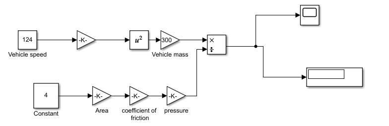
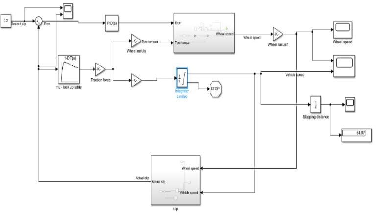
Figure(6)Simulinkmodeloftheconventionalbrake system
3.1 Simulink Model of the Conventional Brake System
| ISO 9001:2008 Certified Journal | Page1101
Vf=Vi+a.t (1)
International Research Journal of Engineering and Technology (IRJET) e ISSN: 2395 0056
A one quarter mathematical model for the conventional brake system was implemented using Matlab Simulink by mathematicalequations.
Volume: 09 Issue: 03 | Mar 2022 www.irjet.net
DsWhere:=Thebrakingdistance(m)
p ISSN: 2395 0072 IRJET Factor value: 7.529
n=numberofpad
DT=(Vf2 Vi2)/2a (4)
µ=Thefrictioncoefficient
© 2022,
By using equation (1), (2), and (3), the travel distance DT canbecalculatedas:
Thevehicleacceleration,a a= Vi2/2Ds (6)
3. BRAKING DISTANCE ANALYSIS
D=Vi.t+1/2.a.t2 (2)
Fb=n µ P A (7)
V=Vehiclespeed(m/sec)
When the car is stopped, the braking force Fb equals the dragforceFd
P=Theoilpressureinthebrakesystem(N/m2)
The braking distance Ds (the distance traveled by car before braking directly) as the car eventually stops (Vf is zero)canbecalculatedas:
Byusingequation(6)and(9)ThebrakingdistanceDscan becalculated
| Impact
m=Vehiclemass(kg)
International Research Journal of Engineering and Technology (IRJET) e ISSN: 2395 0056
N =W (12)
Volume: 09 Issue: 03 | Mar 2022 www.irjet.net
©
Thebar.
Figure(8)Variationofbrakingdistancewithvehiclespeed atdifferentvehicleload
| ISO
Certified Journal | Page1102
directproportionalwiththevehiclespeedatallcoefficient ofFigurefriction.(9)
At a vehicle speed of 100 km/hr, the increase of the coefficientoffrictionfrom0.36to0.4causes adecreasein the braking distance by 12.7 % and the increase of the coefficientoffrictionfrom0.4to0.45causesadecreaseon thebrakingdistanceby11.4%.
3.2 Simulink model of an Anti-Lock Brake System
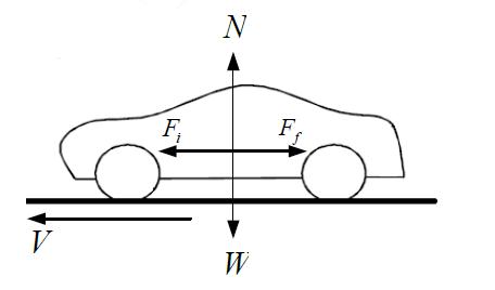
Aone quartermathematicalmodelfortheABSsystemwas implemented using Matlab Simulink by mathematical equationsthatcontroloperationofABSsystem,thismodel has been created in next steps: Considered a vehicle moving in a straight direction under braking conditions figure (10) show vehicle model, write the equations of equilibriumforthehorizontaldirectionas[18]:
effect of vehicle load on the braking distance of the vehicle is presented in Figure (8). It can be seen that the braking distance of the vehicle are increased with increasing the vehicle load. When the vehicle speed increases, the vehicle’s braking distance increases at all vehicleloads,andthebrakingdistancereachesthehighest valueatthefullload.
Ff =μ×mv×g (15)
The effect of coefficient of friction on the braking distance of the vehicle is presented in Figure (9). It can be notice that the braking distance of the vehicle is decreased with increasingofthecoefficientoffriction,itsvaluesincreaseis
WhereFf thefrictionforcebetweenwheelandgroundand Fithe inertial force of the vehicle. Write the equations of equilibriumforverticaldirectionas:
p ISSN: 2395 0072 2022, IRJET Impact Factor value: 7.529 9001:2008
When the vehicle moves with a speed of 100 km/hr, the increase of the vehicle load from 0 to 50% load causes an increaseonthebrakingdistanceby12%while,itincreases by25%atfullload.
Ff =Fi (11)
where; N is normal force (road reaction) and W is vehicle weight.Writetheexpressionsofthefrictionforceas:
|
Figure(7)Variationofbrakingdistancewithvehiclespeed atdifferentbrakeoilpressure.
Atavehiclespeedof100km/hr,byincreasingthebrakeoil pressure from 7 bar to 01 bar, the vehicle’s braking distance decreases about 20%, while its value reduced by 14% with the of the brake oil pressure from 10 bar to 12
Variationofbrakingdistancewithvehiclespeed atdifferentcoefficientoffriction.
where; μ the friction coefficient between wheel and road. Thevehicle’sweightisdefinedas:
W=mv×g (14)
Ff =μ×N (13)
By substituting equation (12) and (14) in equation (13) givestheexpressionofthefrictionforceas:
Fi
International Research Journal of Engineering and Technology (IRJET) e ISSN: 2395 0056
=
Figure(10)Vehiclemodel.
At 100km/hr, the braking distance increases by 3 % with the increasing of vehicle load from 0 to 50%, and 5.5% whenitreachesfullload.
where; mv is the total vehicle mass and g is the gravitationalacceleration
Figure(13)Variationofpredictedbrakingdistanceversus vehiclespeedwith/withoutABS.
Theinertiaforcethatproductbetweenthevehiclemassmv andvehicleaccelerationav as: =mv×av= mv× (16)
Fromequations(1),(5)and(6)thevehicleaccelerationcan bealsocalculatedas: ×μ× ×mv (17)
The effect of braking system type and loads on braking distancesareillustratedandpresentedinFigure(13).
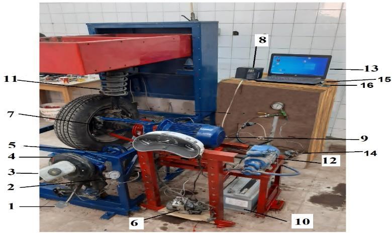
ThetestrigasshowninFigure(14)consistsofmechanical components, electronic components, and the control unit. The mechanical components of the test rig are the disc brake, brake pedal, master cylinder, brake booster, solenoidsvalves,hydraulicpump,andanelectricmotor.
Volume: 09 Issue: 03 | Mar 2022 www.irjet.net
Figure(11)SimulinkmodelofABSsystem.
Theeffectofvehicleloadonthe simulatedvehiclebraking distancewiththeusingofABSispresentedinFigure(12).
p ISSN: 2395 0072 Factor value: 7.529 9001:2008
Figure(12) Theeffectofvehicleloadonthepredicted brakingdistanceusingABSsystem.
Certified Journal | Page1103
© 2022, IRJET | Impact
| ISO
Thisresultshowsthatthebrakingdistanceofthevehicleis directly proportional to the vehicle speed and are slightly increasethevehicleload.
Ascan be seen from the results, with the using of the ABS system at 100 km/hr, the braking distance is reduced by almost30%withoutloadandalmost43%,atfullload.
4. TEST RIG AND MEASURING PROCEDURE
1 Brake pedal 2 Pressure gauge 3 Master cylinder 4 Brakebooster 5 Circularhandle 6 ABS unit. 7 Disc brake 8 Invertar 9 A.C motor 10 Battery 11 Suspensionsystem12 Electricpump13 Computer. 14 Solenoid valve 15 Ultrasonic sensor 16 ArduinoUnoMicrocontroller.
Ultrasonic sensor is operated all the time during driving producingultrasonictransmittedsoundwaves,whenthese waves found an obstacle (vehicles or human) within a certain distance, the sound wave is reflected, the ultra
© 2022, IRJET | Impact
Volume: 09 Issue: 03 | Mar 2022 www.irjet.net ISSN: 2395 0072 Factor value: 7.529 9001:2008
Figure(14)Maincomponentsofthetestrig.
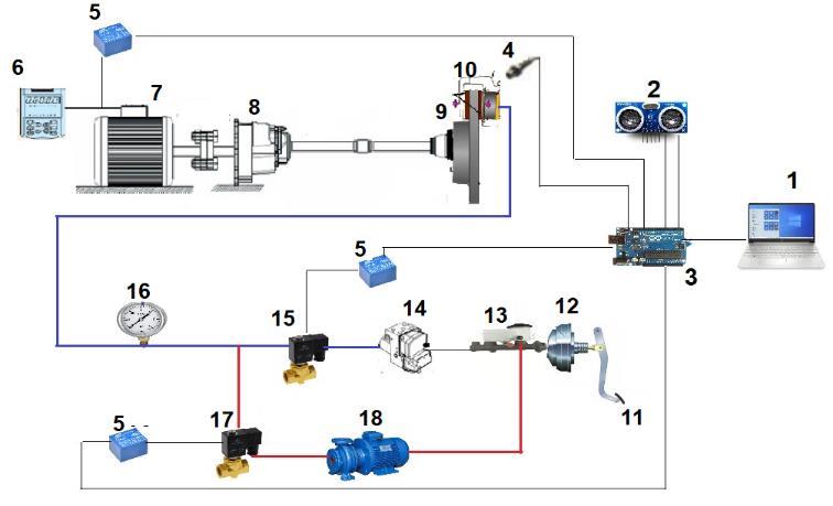
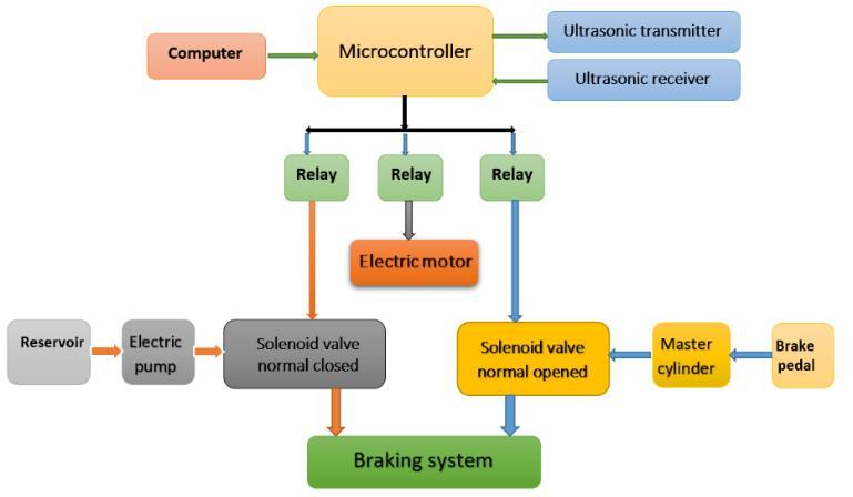
This system consists of two ultrasonic transducers as distancemeasurementsensors,kitofanelectroniccontrol unit to manage the signal input and output of sensor, hydraulic circuit, two solenoid control valves (one normallyclosedwhiletheotherisnormallyopened).
p
Adrumbraketestrigisdesignedtoprovidethenecessary rotational speed and applied pressure to the real braking applications. A brake pedal is used to transfer braking powerfromthedriver'sfoottothemaincylinderandthen to the wheel’s cylinders, and it is also used to enlarge the braking force by an appropriate proportion. Solenoid valves are used to control the direction and pressure of brake fluid. Two types of solenoid valves are used, one solenoid valve is normally open, which is installed after brake pedal, another solenoid valve is normally closed, whichisinstalledaftertheelectricpump.
Certified Journal | Page1104
Anelectricmotorisconnectedtoadiscbrakebyasuitable rod, which is rotating the drum brake by variable speeds, electricmotorcapacityis5HP.
e
1 Computer 2 Ultrasonic sensor 3 Arduino Uno Microcontroller4 ABSsensor5 Electricrelay6 Inverter 7 A.Cmotor 8 Gearbox 9 Rotor/disc 10 Floating caliper 11 Brakepedal 12 Brakebooster 13 Master cylinder 14 ABS unit 15 Solenoid valve normal open 16 Pressuregauge17 Solenoidvalvenormalclosed 18 Electricpump
As shown in Figure (14) and Figure (15), the electronic componentsusedinthetestrigareanArduinoUnoboard, Ultrasonic sensor, and an electric relay. An Arduino Uno board of a microcontroller which used to receive signals fromultrasonic sensorandprocessit,thensendsignalsto electricrelays.
4.1 Automatic Barking Control Strategy
| ISO
Research
International Journal of Engineering and Technology (IRJET) ISSN: 2395 0056
Theelectricpumpisusedtopumpthebrakefluidwiththe appropriate amount and pressure to stop rotation of disc brake,itoperatingoverpressure30barandthemaximum volumeflowrateis0.25L/sec.
The sensor uses Input/output trigger for 01μs high level signal, it automatically sends eight 40 kHz and detects for pulse signal and note down the time taken for waves to bounceback.
Test distance = travel time the × velocity of sound. Knowing the speed of sound, the sensor determines the distance of the target and sets its outputs accordingly. It provides a range of 2 450 cm non contact measurement function,therangingaccuracycanreachto3mm[30].
Anelectronicrelayactsasaswitchwhichisturnedonand off using a signal. It is controlled through the digital I / O port,suchassolenoidvalves,lamps,motors,andotherhigh current or high voltage devices. It used to control open or closed solenoids valves by signals from the microcontroller. To perform the measurements for different distances, Senix ultrasonic (RS232) sensors are used, which providesa measurement rangof 4 1500cm ofnon contactmeasurementfunction.
Figure(15)Aschematicdiagramofthetestrig
Volume: 09 Issue: 03 | Mar 2022 www.irjet.net
The measured and simulated braking distance for vehicle withABSsystemispresentedinFigure(18).
©
International Research Journal of Engineering and Technology (IRJET) e ISSN: 2395 0056
| ISO
Figure(18)Measuredandsimulatedbrakingdistance versusthevehiclespeedatdifferentloadsusingABS.
p ISSN: 2395 0072 2022, IRJET Impact Factor value: 7.529 9001:2008
Certified Journal | Page1105
If the measured distance between the obstacle and the vehicle is less than the desired distance which can be adjusted, the control unit sends a signal to activate the electronicrelaytoopenthesolenoidvalvenormallyclosed andclosed the solenoid valve normally open,andstop the electric
The hydraulic pump draws the hydraulic oil from the reservoir and presses the fluid in the pipes to the disc brake piston which push the disc shoes and stop the Aftervehicle.braking
Itcanbenoticethatthereisaslightincreaseinthevalueof the measured than the simulated braking distance, eps. at highspeeds.
The measured braking distance of the conventional brake systemandABSispresentedinFigure(19). Itcanbeseen that the measured braking distances are slightly higher than the simulated results. At vehicle speed of 72 km/hr, theresultsshowthatthereare5%incaseofnoload,8% athalfvehicleloadand9.8%atfullvehicleload.
|
Braking performance reflects the capacity at which the vehicle stops in a short time and maintains movement stability. The approximate braking time is the amount of time the vehicle takes to reach a complete stop after applying brakes and the braking distance is the distance required for a vehicle that moves at a specific speed to reach full stop after the brake is activated so, the braking time and braking distance are an important indicator to evaluate braking performance. In this paper, complete comparison between predicted and measured braking distanceareanalysis.
Figure(17)Measuredandsimulatedbrakingdistance versusvehiclespeedatdifferentvehicleloadsofthe conventionalbrakesystem.
Figuremotor.(16)
sonic emitter sends signals to the microcontroller, which processesit. Figure(16)showsaschematicdiagramofthe controlprogram.
5. RESULTS AND DISCUSSION
Blockdiagramofnormal(blue)and/or automatic(red)brakingsystemworkingmethodologies.
The measured and predicted braking distance using a conventional brake system at different vehicle loads are presented in Figure (17). The results show that the simulation agrees well with the measured result The maximumdifferencebetweenthemeasuredandpredicted resultsat72km/heis3%atfullload.
In order to design and implement test rig, the braking distanceofthecarwasstudiedandanalyzed,andthiswas tested on the conventional brake system and the anti lock brake system, and the following is a presentation of the results.
the vehicle, the activated solenoid valves return to their original positions and the hydraulic oil go back normallytoreservoir.Figure(16)showsa schematic diagramofthecontrolprogram.
International Research Journal of Engineering and Technology (IRJET) e ISSN: 2395 0056
Toevaluatetheemergencybrakesystemperformance,the measuredbrakingtimeorbrakingtimehasbeenmeasured atdifferentdistances.Ateachdistance,thebrakingtimeof the vehicle was measured at five different speeds. The measured braking distance or braking time has been measured to compare between the measured and predicted braking time. The measured and calculated braking distance is presented in Figure (20). It can be notice, with the using of the ABS instead of the conventional braking system at 72 km/hr, reduces the braking distances by about 25% without load and 35% at full
Using the ABS, there is a good agreement between the measured and simulated braking distance at different speedsandloads
[1]. Bosserdt, P. I. "ANTI LOCK BRAKE SYSTEM." Youth and science: Collection of materials of the VII All Russian scientific and technical conference of students, graduate students and young scientists, dedicatedto.2011.
The vehicle braking distance are increased with increasingofitsload.Whenthevehiclespeedincreases its braking distance increases at all vehicle loads. At a vehiclespeed of100km/hr,theincreaseofthevehicle loadfromnoloadtofullloadcausesanincreasesinthe brakingdistanceby25%.
The measurements were performed at three distances betweenthesystemandanobstacle.Thesedistancesare5, 10 and 15 meters. The braking time is measured at four different vehicle speeds; these speeds are 30, 50, 70, 90, and110Km/hr.Themeasuredbrakingdistanceatdifferent loads are presented in Figure (20). The results show that there is an increase in the measured braking time with increasevehiclespeedatdifferentloads.Atavehiclespeed of 72 km/hr, the braking distance increase by 15%, and 30% when the vehicle load varied from 0 to 50% and 100%respectively.
[3]. Samuel John(0418571X)PhDthe sis”Developmentof Nonlinear Real Time Intelligent Controllers for Anti lockBrakingSystems(ABS)”
6. CONCLISIONS
p
Figure(19)Measuredbrakingdistanceusingthe conventionalbrakeandABS.
The braking distance of the vehicle are increased with increasing the value of the coefficient of friction. At vehicle speed of 100 km/hr, the increase of the coefficient of friction from 0.36 to 0.4 causes a decreasesinthebrakingdistanceby12.7%
By using the ABS instead of the conventional braking system at a vehicle speed of 72 km/hr, reduces the brakingdistancesbyabout25%withoutloadand35% atfullloads.
Volume: 09 Issue: 03 | Mar 2022 www.irjet.net ISSN: 2395 0072 Factor value: 7.529
The measured and predicted Ds are in a very good agreementatalloperatingconditions.
[4]. M. Omae, T. Ogitsu, N. Honma, and K. Usami, “Automatic driving control for passing through
Usingtheemergencybrakingsystem(EBS)at72Km/hr and full reduced the stopping distance about 20% comparingwiththeABS.
REFERENCES
| ISO 9001:2008 Certified Journal | Page1106
loads.Figure
At constantload, the measured braking distance of the vehicle are reduced with increasing of the brake oil pressure. With the increasing of the vehicle speed, the vehicle’s braking distance increasesatall pressures.At a vehicle speed of 100 km/hr, by increasing the brake oilpressurefrom01barto01bar,thevehicle’sbraking distancedecreasesabout14%.
The main conclusions from the present study can be summarizedinthefollowingpoints:
© 2022, IRJET | Impact
(20)Themeasuredbrakingdistanceofthe automaticemergencybrakingsystem.
[2]. Mohan, S. "Design and Development of an Improved Anti LockBrakingSystemforTwo Wheelers."(2011).
[5]. Sushil Kumar, Vishal Kumar, Automatic Emergency Braking System International Journal of Research in Science & Engineering, e ISSN: 2394 8299, Volume: 1 Issue:3pages93 96,2017.
[14].NishadVivekKumbhojkar& ChaitanyaAvadhutchintanKuber ‘’Ultrasonic Automatic Braking System For Forward Collision Avoidance With Accelerator Pedal Disengagement Mechanism’’, International journal & magazine of engineering, technology, management and research registrar of Newspapers of India(RNI) Regd No: [15].APENG/47294/2011.Lu,Yan,Piao,&Zhang, Lu, S., Yan, B., Piao, C. H., & Zhang, Q. : An Automatic Braking System in the Reversing Based on Electric Vacuum Booster:
[12].Swastik Pradhan, 2Rama Seshu. Y, 2Jitesh Nagaraj. J. Automatic braking system. Journal of Emerging Technologies and Innovative Research, Volume 5, Issue12,2018.
[7]. Dineshkumar C, Subramanian M “Automotive braking system for passenger vehicle to enhance safety”.
Mrudula, Kumar, T. U. A. S., & Mrudula, J. : Advanced Accident Avoidance System for Automobiles:,6(2),79 83,2013.
Mohamed Watany,” Performance of a Road Vehicle with Hydraulic Brake Systems Using Slip Control Strategy” American Journal of Vehicle Design, (0), pp7 18,2014.
[21].Gawande, Gavhale, Zariye, & Ritpurkar, Gawande, G. P.,Gavhale,S.V,Zariye,I.A.,&Ritpurkar,S.P.:Review ofSpeedControlandAutomaticBrakingSystem:,3(2), 474 477,2014.
|
Journal | Page1107
Volume: 09 Issue: 03 | Mar 2022 www.irjet.net p ISSN: 2395 0072 2022, IRJET Impact Factor value: 7.529 9001:2008 Certified
[13].Hemalatha B K, P Pooja, ChaithraM,MeghaS,Rakshitha R.T ‘’Automatic Braking System for Automobiles Using IR Sensor’’ (IJAREIE) International Journal of Advanced Research in Electrical,Electronics nd Instrumentation Engineering(AnISO3297:2007.
Advanced Materials Research, 580, 360 [17].[16].0.360,https://doi.org/10.4028/www.scientific.net/AMR.58364,2012.Jeyanthi,Jeyanthi,R.:Automaticbrakingsystemwithsensorfusionconcept1:4(June),2327,2012.Mr.VidyadharM,Mr.MUpendarreddy,Mr.
©
[9]. Halderman, J.D.: Automotive Brake system: Prentice Hall,Inc,NJ,USA,1996.
International Journal of Pure and Applied Mathematics Volume 117 No. 20 2017, 1011 1020 ISSN: 1311 8080 ISSN: 1314 3395 (on line version). (2018).
Vidhyapathi C M, Mr. Dhanabal R, “Anti collision and auto retarding system along with a wiper speed control during rains using MPS 321 microcontroller”, International Journal of Engineering and Technology [18].(IJET),2013.Sairam,Suresh, Hemanth, & Krishna, Sairam, G. V, Suresh,B.,Hemanth,C.H.S.,&Krishna,K.:Intelligent MechatronicBrakingSystem:,3(4),3 8,2013.
| ISO
[8]. K. M. S. V. M. J.V.Sai Ram, G.Pavanth, B.Jagadeep ,Dr. B.Raghu Kumar, "Automatic Braking System Using UltrasonicSensor,"InternationalJournalofInnovative Science and Research Technology vol. 2, pp. 398 404, 2017.
[10].BOSCH Automobile Hand book: 4th edition, [11].October,1996.
[19].Dubey & Ansari, Dubey, S., & Ansari, A. W. : Design and Development of Vehicle anti collision System using Electromagnet and Ultrasonic Sensors:, (1), 80 [20].83,2013.Kumar&
intersection without stopping,” Int. J. Intell. Transp. Syst.Res.,vol.8,no.3,pp.201 210,2010.
[23].Lewis, Karthik, Lobo, Valder, & Rijesh, Lewis, J., Karthik, B. M., Lobo, J. M., Valder, J., & Rijesh, M. : Fabrication of an Automated Collison Avoidance System Using Ultrasonic Sensor :, 6, 97 101. [27].[26].[25].[24].https://doi.org/10.59/c.jmea.201601.18,2016.Scholar.Scholar,U.G.(2016).:Intelligentvicinityadapterforautomobiles:1,230236,2016.Kavatkar,Salvi,&Rahate.Kavatkar,T.,Salvi,H.,&Rahate,M.:DesignandAnalysisofIntelligentBrakingSystem:,5(1),119131,2017.Ingle,Bambal,&Shobhane,Ingle,A.H.,Bambal,R.K.,&Shobhane,S.:IntelligentBrakingSystem:InternationalJournalofResearchInScience&Engineering,2017.Uikey&Singh,Uikey,S.,&Singh,R.M..:ANTILOCKANDAUTOMATICBRAKINGSYSTEMS:,(3),6871,2017.
[6]. https://www.lesschwab.com/article/complete guide to disc brakes and drum brakes.html
International Research Journal of Engineering and Technology (IRJET) e ISSN: 2395 0056
[22].Thakur & Thakare. Thakur, D., & Thakare, A. P. : A Review on Implementation of FPGA for Automatic ReverseBrakingSystem:,4(1),2013 2015.
p ISSN: 2395 0072 2022, IRJET Impact Factor value: 7.529 9001:2008
Fathy Nader is an Instructor at Industrial Technical Institute in El Sehafa, Technological College of Sehafa, Ministry of Higher Education in Egypt from 2012 till now. He received M.Sc. in Automotive and TractorsTechnology2017.


Certified Journal | Page1108
|
Khaled Abdelwahed is an Assistant Professor at Automotive Technology Department,HelwanUniversity.Hereceived his B.Sc. (1990) and M.Sc. from Eindhoven University of Technology (The Netherlands, 1997). In 2018 he received his Ph.D. in Automotive Technology from Faculty of Industrial Education, Helwan University, Cairo Egypt. His research interest includes Auto. Technology and Teaching Methods in Auto.Technology.
International Research Journal of Engineering and Technology (IRJET) e ISSN: 2395 0056
Volume: 09 Issue: 03 | Mar 2022 www.irjet.net
| ISO
[28].M.S.B.SAHRI,"ULTRASONICCARBRAKINGSYSTEM "UNIVERSITIMALAYSIAPAHANG,pp.1 24,2016.
[29].A.P.Blancas,M.Eduardo,L.Lopez,R.M.Caporal,and R. O. Flores, “Simulation of the ABS Braking System Behavior in Critical Faults,” no. November, 1108, doi: [30].10.21275/ART20202369.Hamdy.Aboeldaheb, "ASSESSMENT AND DEVELOPMENT OF AN INTELLIGENT BRAKING SYSTEM WITH ITS EDUCATION APPLICATIONS" UNIVERSITIHELWAN,MasterThesis,2019.
©
Sabry Allam, is a Professor of Automotive Engineering at Helwan University in Egypt. He is a previous Dean of the Faculty of Technology and Education, Helwan University, Cairo, Egypt. He has more than 100 research paper in various automotive engineeringresearchtopics.
BIOGRAPHIES