Aboli M. Dobale1 , Dr. Rashmi A. Keswani2
Key Words: 3 phaseIM,voltagesourceinverter,Zsource inverter,Controller,SPWM
1.INTRODUCTION
© 2022,
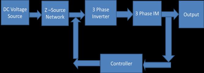
source, 3 phase Voltage Source inverter, and 3 phase induction motor. In a traditional voltage source system, constant dc voltage is applied to 3 phase inverter. The inverterconsistsof6IGBTswitches,forgatepulsetriggering hereSPWMtechniqueisused.SPWMtechniquecomparesthe sinewaveandcarriersignalwaveusingrelationaloperator, andoutputisgiventotheinverterpulses.Theoutputofthe inverter is fed to a three phase induction motor, and the output performance characteristics of the three phase induction motor [Stator current, Torque, and Speed] are studiedandanalyzed.
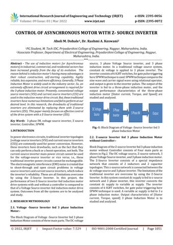
2.2. Z source Inverter fed 3 phase Induction Motor withoutController:
BlockDiagramoftheZ sourceInverterfed3 phaseinduction motor without Controller consists of Four main parts as showninFig.2.TheDCvoltagesource,Z sourcenetwork,3 phaseVoltageSourceinverter,and3phaseinductionmotor. The Z Source Inverter consists of a special impedance network that consists of 2 inductors and 2 capacitor topologies.Thisz sourcenetworkisconnectedbetweenthe dcvoltagesourceand3phaseinverter.Thelimitationsofthe traditional inverter are overcome by using the Z Source Inverter.Inthissystemconstantdcsupplyisfedtoz source network and 3 phase inverter, this inverter converts the constant dc supply to variable ac supply. The inverter consists of 6IGBTswitches, for gatepulsetriggering here SPWMtechniqueisused.Avariableacsupplyisfedto3a phase induction motor. Output characteristics of [Stator current, Torque, speed] 3 phase Induction Motor is to studiedandanalyzed.
International Research Journal of Engineering and Technology (IRJET) e ISSN: 2395 0056

CONTROL OF ASYNCHRONOUS MOTOR WITH Z- SOURCE INVERTER
TheBlockDiagramofVoltage SourceInverterfed3phase InductionMotorconsistsofthreemainparts.TheDCvoltage
1PG Student, M. Tech IDC, Priyadarshini College of Engineering, Nagpur, Maharashtra, India.
Fig. 1:BlockDiagramofVoltage SourceInverterfed3 phaseInductionMotor

Abstract The use of induction motors [or Asynchronous motors] in industrial, commercial, and residential sectors has been increased greatly from the day of its evolution. The reason behind is induction motor's having many advantages is their robust construction, self starting capability, highly reliable, less expensive, and more efficiency. Generally, 3 Phase Induction Motor is widely used in the industry sector. So, an extremely efficient drive circuit arrangement is required for the 3 phase induction motor. Presently, conventional voltage source inverters (VSI) and current source inverters (CSI) are used in the induction motor drive circuit. But, these traditional inverters have numerous limitations and fail to perform at our desired level. In this research, the drawbacks of traditional inverters are eliminated by replacing them with Z source inverters (ZSI). This paper mainly focuses on effective control of the drive system with a Z Source inverter (ZSI).
| ISO
Certified Journal | Page1051
Volume: 09 Issue: 03 | Mar 2022 www.irjet.net
p ISSN: 2395 0072 IRJET Factor value: 7.529 9001:2008
2Associate Professor, Department of Electrical Engineering, Priyadarshini College of Engineering, Nagpur, Maharashtra, India. ***
Inpowerelectronicscircuits,traditionalinvertertopologies [voltagesourceinverters(VSI)andcurrentsourceinverters (CSI)]arecommonlyusedforpowerconversion.However, theseinvertershavedrawbacks,suchasthefactthatthey canonlyperformabuckoraboostoperation,notboth.The current sourceinvertermainpowercircuitcannotbeused for the voltage source inverter or vice versa; i.e., these traditionalinverterpowercircuitscannotbeexchangeable. Theelectromagneticinterference(EMI)noiseiscreateddue to shoot through and open circuit problems in voltage sourceinvertersandcurrentsourceinverters,whichreduce theinverter’sreliability.Thesearealllimitationsovercome by using the Z Source Inverter. In this project, the performanceoftwoZ Sourceinverter fedinductionmotor drivesystemswithandwithoutacontrolleriscomparedto thatofaVoltageSourceinverter fedinductionmotordrive system.Outcomesfromall thesystemsareto beanalyzed andstudy.
| Impact
2.12.RESEARCHMETHODOLOGY.VoltageSourceInverter fed 3 phase Induction Motor:
Fig 4: SimulationmodelofVoltagesourceInverterfed3 phaseInductionMotor
e
3.13.MATLABSIMULATIONANDANALYSIS.MATLAB/SimulinkModelimplementation of Voltage-SourceInverterfed3phaseInductionMotor:-
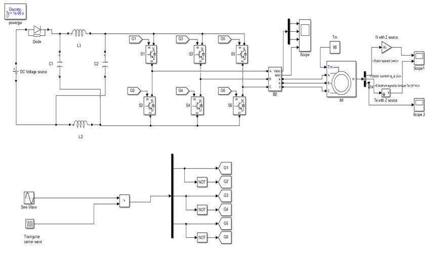
In this section, MATLAB/Simulink is used for Z source Inverter fed 3 phase Induction Motor without Controller. Thismodelconsistsofauniquez sourcenetworkwhichis connectedbetweenconstantdcvoltageand3phaseinverter. The related techniques which are used to implement this model have been discussed in Sections 2.1 and 2.2. Fig. 5 shows the Simulink model of the Z source Inverter fed 3 phaseInductionMotorwithoutController.

International Technology (IRJET) ISSN: 2395 0056
Inthissection,MATLAB/Simulinkisusedforthesimulation ofVoltage SourceInverterfed3phaseInductionMotor.The relatedmethodologywhichisusedtoimplementthismodel hasbeendiscussedinSections2.1.Fig.4showstheSimulink modeloftheVoltage SourceInverterfed3phaseInduction Motor.
www.irjet.net p
Fig 5: SimulinkmodeloftheZ sourceInverterfed3 phaseInductionMotorwithoutController.
2.3.Z Controller:sourceInverterfed3phaseInductionMotorwith
BlockDiagramofaZ sourceInverterfed3phaseinduction motorwithaControllerconsistsofFivemainpartsasshown inFig.3.TheDCvoltagesource,Z sourcenetwork,3phase Voltage Source inverter,3 phase induction motor, and PI Controller.Thissystemconstructionandworkingaremostly similar to Z source Inverter fed 3 phase induction motor without Controller but here additional PI controller is connectedinthesystem.Inthissystem,3phaseinduction motorspeediscontinuouslymeasuredandcomparedwith the reference speed. A discrepancy in actual speed and referencespeederrorsignalisshownbyPIController.The outputofthePIcontrollerisfedto3phaseinductionmotor at an appropriate speed. Output characteristics [Stator current,Torque,speed]of3phaseInductionMotorcanbe controlled as compared to Voltage Source Inverter fed 3 phaseInductionMotorsystemandZ sourceInverterfedIM withoutControllersystem.
Research Journal of Engineering and
3.2. MATLAB/ Simulink Model implementation of Zsource Inverter fed 3 phase Induction Motor without Controller:

7.529 | ISO 9001:2008 Certified Journal | Page1052
Volume: 09 Issue: 03 Mar 2022 ISSN: 2395 0072 Factor value:
© 2022, IRJET | Impact
Fig 2: BlockDiagramofZ sourceInverterfed3phase InductionMotorwithoutController
Fig 3: BlockDiagramofZ sourceInverterfed3phase InductionMotorwithController
|
Themotorusedis3 phaseStarConnectedInductionmotor, Rotortype Squirrelcage,withtheratingas [4Pole,20HP, 15KW,400V,50HZ,1460RPM,98Nm,36A]
5 Magnetizing
Volume: 09 Issue: 03 | Mar 2022 www.irjet.net p ISSN: 2395 0072 2022, IRJET | Impact Factor value: 7.529 | ISO 9001:2008 Certified Journal | Page1053
6 Stator
Table1: Inductionmotorrating
SN. Parameters Rating Resistance[Rs] 0.2147Ω Resistance[Rr] 0.2205Ω LeakageInductance[Lls] 0.991mH RotorLeakageInductance[Llr] 0.991mH Inductance[Lm] 64.19mH Reactance[Xs] 0.31133Ω Reactance[Xr] 0.31133Ω
4.RESULTSANDDISCUSSION
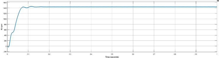
Fig 7:RotorspeedVsTimecurveofVoltage sourceinverterfedInductionmotor
3 Stator
7 Rotor
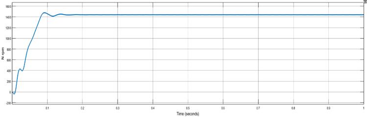
Fig-8:RotorspeedVsTimecurveofZ sourceInverterfed InductionMotorwithoutController.
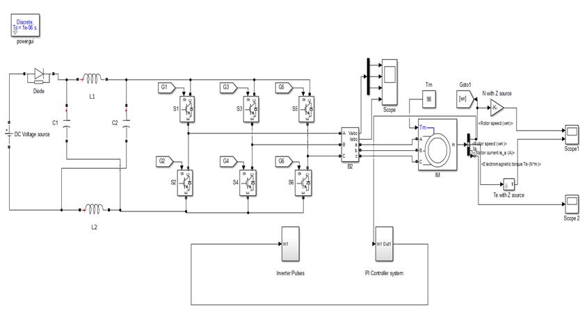
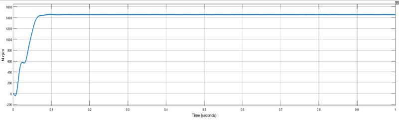
Fig 9:RotorspeedVsTimecurveofZ sourceInverterfed InductionMotorwithController
Fig-6: SimulinkmodeloftheZ sourceInverterfed3phase InductionMotorwithController.
In this section, MATLAB/Simulink is used for Z source Inverter fed 3 phase Induction Motor with Controller. The corresponding method which is used to implement this modelhasbeendiscussedinSections2.3and2.1.Figure6 shows the Simulink model of the Z source Inverter fed 3 phaseInductionMotorwithController.
4
©
3.4Inductionmotorrating:-
1 Stator
TheoutputwaveformofVSIfedIMsystem,ZSIfedwithout Controller,andZSIfedwithControllersystemintheMATLAB simulation is. The waveform of Speed Vs Time, ElectromagneticTorqueVsTime,StatorCurrentVsTimeare discussedhere.
TheRotorspeedVsTimecurveofVSIfedIMsystem,ZSIfed withoutController,andZSI fedwithControllersystemare showninfig.7,fig.8&fig.9respectively.InVSIfedIMsystem Oscillation of rotor speed is more than, ZSI fed without ControllerandZSIfedwithControllersystem.
3.3. MATLAB/ Simulink Model implementation of Z source Inverter fed 3 phase Induction Motor with Controller:
2 Rotor
International Research Journal of Engineering and Technology (IRJET) e ISSN: 2395 0056
ObservationTable2: BasedonRisetime[second]: Inverter 3 InphaseInductionmotorparametersSpeedInTorqueInStatorcurrent
Volume: 09 Issue: 03 | Mar 2022 www.irjet.net ISSN: 2395 0072 2022, IRJET Impact Factor value: 7.529 9001:2008 Certified Journal 1054
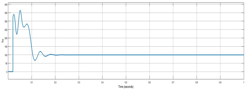
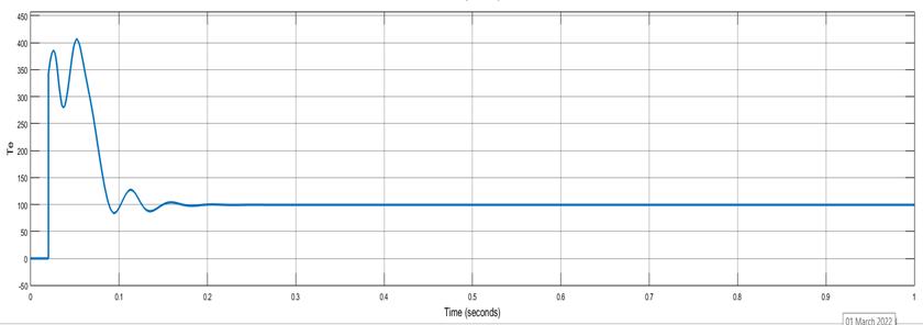
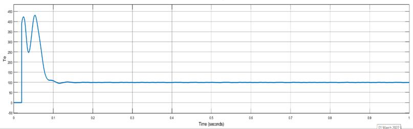
The Electromagnetic Torque Vs time curve of VSI fed IM system,ZSIfedwithoutControllerandZSIfedwithController systemisshowninfig.10,fig,11&fig.12respectively.InZSI fed without Controller and ZSI fed with Controller system time rate and oscillation of generating torque is less. As a result,notonlydoesthemotorrunatthebestspeedquality but also power regenerative capacity is increases as comparedtoVSIfedIMsystem.
p
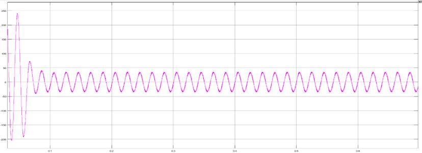
Fig 13: StatorCurrentVsTimecurveofVoltagesource inverterfedInductionmotor
| ISO
TheStatorcurrentVsTimecurveofVSIfedIMsystem,ZSI fedwithoutControllerandZSIfedwithControllersystemis shownfig,13,fig.14&fig.15respectively.InZSIfedwithout Controller and ZSI fed with Controller system obtained smooth output waveform as well as for settling and rising timeislessascomparedtoVSIfedIMsystem.
International Research Journal of Engineering and Technology (IRJET) e ISSN: 2395 0056
|
Fig 12: ElectromagneticTorqueVsTimeofZ source InverterfedInductionMotorwithController.
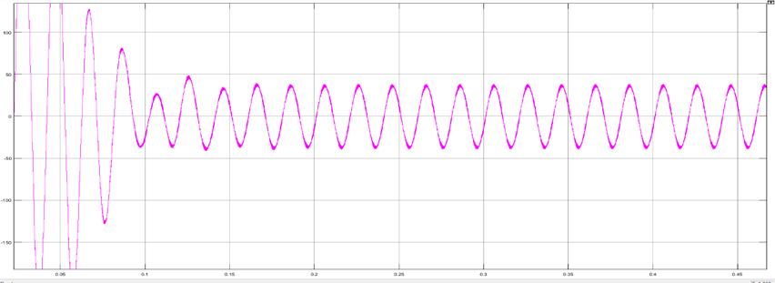
Fig 11: ElectromagneticTorqueVsTimeofZ source InverterfedInductionMotorwithoutController.
Fig 14: StatorcurrentVsTimeofZ sourceInverterfed InductionMotorwithoutController
©
Fig-15: StatorcurrentVsTimeofZ sourceInverterfed InductionMotorwithController

Fig 10: ElectromagneticTorqueVsTimecurveofVoltage sourceinverterfedInductionmotor
| Page
ZSI ControllerWithout 0.085sec 0.053sec 0.007sec
International Research Journal of Engineering and Technology (IRJET) e ISSN: 2395 0056
© 2022, IRJET | Impact Factor value: 7.529 | ISO 9001:2008 Certified Journal | 1055
[3] R.Malathi,M.RathinaKumar,R.TheGobi,“Closed loop ControlOfZSIFedInductionMotorDriveUsingPIAnd Fuzzy Logic Controllers”, International Journal for ResearchinEngineeringApplicationandManagement (IJREAM)ISSN:2454 9150, Vol.4,Issue6,September 2018.
[10] PohChiangLoh;MahindaVilathgamuwa,D.;YueSenLai; GeokTinChuaandYunweiLi“Pulse WidthModulation of Z source Inverters”, IEEE Transactions on Power Electronics,Vol.20,No.6.(2005).
Inverter 3
VSI 0.095sec 0.054sec 0.008sec
ZSI ControllerWith 0.075sec 0.052sec 0.005sec
VSI 0.18sec 0.18sec 0.17sec
ZSI ControllerWithout 0.16sec 0.16sec 0.15sec
[5] R.A.Keswani, U.E.Hiwase, “MRA analysis for fault identification in multilevel inverter” International Research Journal of Engineering and Technology (IRJET),Vol.4,No.6,2017,pp.2168 2171
ObservationTable3: BasedonSettlingtime[second]:
Page
[2] Anant Thakur, “Z Source Inverter Fed Asynchronous Motor Drive”, International Journal of Trend in Scientific Research and Development (IJTSRD) ISSN: 2456 6470,Vol.4,Issue1,December2019.
5.CONCLUSION
[4] R.Kapil,Dr.Vijayaragavan,“Z SourceInverterFedThree PhaseInductionMotorDrivewithPIandPIDControlled close closed looptems”, International Journal of Advanced Research in Electrical, Electronics, and Instrumentation Engineering (IJAREEIE) ISSN: 2320 3765,Vol.6,Issue10,October2017.
[7] Mahima Sharma, Mahendra Lalwani, “Performance Evaluation of Three Phase Induction Motor Drive Fed fromZ sourceInverter”,InternationalJournalofApplied Engineering Research ISSN 0973 4562 Volume 13, Number8(2018)
[8] FangZhengPeng;AlanJoseph;JinWan;MiaosenShen; Lihua Chen, Zhiguo Pan; Eduardo Ortiz Rivera and Yi Huang “Z source Inverter for Motor Drives”, IEEE Transactions On Power Electronics, Vol. 20, No. 4. (2005).
[9] Baba,M.;Lascu,C.andBoldeaI.“Zconvertercontrolofa V/F induction motor drive” IEEE conf. On Industry ApplicationsConference(2012).
[6] OmarEllabban;JoeriVanMierloandPhilippeLataire, “ComparisonbetweenDifferentPWMControlMethods for Different Z source Inverter Topologies”, The 13th European Conference on Power Electronics and Applications.8 1,EPE'090.(2009)
ZSI ControllerWith 0.13sec 0.13sec 0.11sec
Volume: 09 Issue: 03 | Mar 2022 www.irjet.net p ISSN: 2395 0072
REFERENCES
[1] Basanti Bhagat, Gurpreet Singh, “Performance and Evaluation of Voltage Source Inverter Fed Induction Motor Drive”, International Research Journal of EngineeringandTechnology(IRJET)ISSN:2395 0056, Vol.6,Issue2,Feb2019
InphaseInductionmotorparametersSpeedInTorqueInStatorcurrent
The performance of two Z Source inverter fed induction motor drive systems with and without controller and Voltage Source inverter fed induction motor drive system modellingusingMATLAB/SimulinkandOutcomesfromall the systems are compared and discussed. From the observationsandoutputperformancecharacteristics,itcan be concluded that all limitations of the voltage source invertersareovercomedbyusingtheZ SourceInverter.The Z Source inverter fed induction motor drive systems with andwithoutacontrollerhaslesstorqueripples,improved stator current quality, better settling time, and obtained smooth output waveforms for the same valueof speed [1460RPM]Electromagnetictorque[98NM],Statorcurrent [36A]ascomparedtoVoltageSourceinverter fedinduction motordrivesystem