Kakatiya Institute of Technology And science Warangal, India
The flywheel has been utilized since prehistoric times. It stores energy by spinning and utilizing the moment of inertia. The energy will be stored within that cylinder disc may beused byconnectingitto themedium towhichwewishtotransmitenergyasitspins.Flywheels arefrequentlyusedinconjunctionwithenginestoprovide power to a machine or vehicle. They may also be used to gather kinetic energy while braking on bicycles; kinetic energy willbestoredaspotentialenergyandtransitioned back when needed.. Their great efficiency may lead to the substitution of electrochemical cells for kinetic energy storage or rotational energy storage. In our project, we intend to put our expertise to use by constructing a flywheelthatwillbefittedintoabicycle.
ABSTRACT: KERSisanacronymforKINETICENERGYRECOVERYSYSTEM.It isusedtorecoverenergylostduringbreaking as well as to transform kinetic energy loss into kinetic energy gain. When riding a bicycle, braking consumes a significant amountofenergy.Weemployedamechanicalkineticenergyrecoverysystemwithaflywheeltostoreenergythatisordinarily lost while braking and then reuse it to assist the rider in driving after a rest. The engagement disengagement mechanism transfers kinetic energy from the back wheel to the flywheel through chain drive. During the pause, the flywheel stores the availableenergyandpowerstherearwheelbackup.TherecoveryspeedofKERSisextremelyslowintheoryandsignificantly worseinpractice.Theweightoftheflywheelcanbeincreasedtoincreasetherecoveryspeedandhenceefficiency.However, puttingtoomuchweightonbikewillpreventyoufromcyclingnormally.Theidealflywheelweightisbetween5and8kg.We will use the Fusion 360 software to create the bicycle, and then we will utilize Ansys to simulate the model. We'll also determinethespeedratiobydeterminingthespeedofabicyclewithandwithoutaflywheel
Kumar Sai Nidamanuri3
Keywords: Fusion 360, Ansys, KERS, Flywheel.
SharathchandraGurrapu1
3Research scholar Mechanical engineering
Chapter 1: Introduction
Design and Analysis of Kinetic Energy Recovery System using Flywheel in Bicycle

Chapter 2: Literature review
Kakatiya Institute of Technology And science Warangal, India
***
The clutch plate linked to the flywheel axle is always moved by the crank wheel attached to the rear wheels. This is accomplished by employing a specified gear ratio chain transmission cranked to the clutch sprocket, which allowstheflywheel'stotalspeedtoberaised. Theclutchis engaged when deceleration is necessary, causing contact between the clutch and the flywheel. The flywheel then beginstorevolve,reducingthebicycle'sspeed.Asaresult, a system of regenerative braking is developed. then acceleratewhileregularriding,increasingthedistance we cantravelbybicycling.
Mechanical engineering
International Research Journal of Engineering and Technology (IRJET) e ISSN: 2395 0056 Volume: 09 Issue: 03 | Mar 2022 www.irjet.net p ISSN: 2395 0072 © 2022, IRJET | Impact Factor value: 7.529 | ISO 9001:2008 Certified Journal | Page948

D. K. Naresh Kumar et al. devised and built a flywheel bicycle with a mobile charger that captures the kinetic
1Research scholar
2Assistant professor Mechanical engineering
Kakatiya Institute of Technology And science Warangal, India
The flywheel's most conceivable characteristic is its high power density and storage capacity. The development of materials such as carbon fiber and light anodized aluminum alloys has enhanced the power densities of flywheels while decreasing their weight and theamountofeffortrequiredtoovercometheirstationary inertia. The usage of such materials simplifies their applicationtoabicycle
V. Laxmi Priyanka2
2.1 Previous Work
1.1 KERS Bicycle Operation:
Chapter 3: Problem Definition
2) Optimizing the present KERS design and developinganewdesign.

3.1 Project Outline
FlywheelLoad=10kg
1) A summary of significant technologies for recoveringkineticenergy.
CHAPTER: Calculation4for
OurdesignstrategyistoconstructaKERSflywheelenergy storage unit as a proof of concept, which we intend to optimize.Asystemlikethisisviablesinceroadsacrossthe world include various obstructions like as junctions, automobiles,andturnsthatprohibitabikefromkeepinga steady pace. This method will aid in the recovery of brakingenergywastedduetotheseobstructions.
Loadofbicycle=10kg
International Research Journal of Engineering and Technology (IRJET) e ISSN: 2395 0056 Volume: 09 Issue: 03 | Mar 2022 www.irjet.net p ISSN: 2395 0072 © 2022, IRJET | Impact Factor value: 7.529 | ISO 9001:2008 Certified Journal | Page949
Letusassume
Payloads=10kg
Initialvelocity=u=0kmph
Energyofsystemwhenitreaches10kmph
4) Identifying the external and internal factors that haveboostedordiminishedKERSefficiency.
neededpower,torqueisrequiredatthecentre ofthewheel.
F=Fa+FR+FA+Ff=58.38+7.58+6.77+2
Fig: KERS
E=1/2mv2=0.5*105*2.782=405.741joules
F= To74.73Ngetthis
Totalforcerequired
NishadKumbhojkaretal.discoveredthattheflywheeland gearboxincreasedthe weightofthebicycleintheirstudy. The increased weight increases the amount of energy requiredtoaccelerateandgouphillonthebike.However, after the rider has been given enough power to reach cruising speed, the flywheel assists in additional acceleration, lowering the energy cost of slowing down from that level. Because they are flat and provide several opportunities to lower rider speed, roads are great for flywheel cycling. Using weight scales, the author discovered that for typical riding, the optimal weight for highefficiencyis5kg.[2}
IdentifyingtheKERSpotentialforbicycles.
V=10kph=10*5/18=2.78m/sec
Assume the flywheel has enough energy to propel the bicyclefromastandstillto10kmphin5sec
3) Testing the newly built KERS for bicycles in a varietyofcircumstances.
Tw=F*r=74.73*0.3325
Time=5sec;a=(v*u)/time=2.78/5=0.556m/sec2
5) Highlighting the limits of the intended design and recommending additional work for the KERS design
3.2 Project Objectives
Loadoftherider=75kg
Tw=24.84N m
Totalweight=105kg
energy stored in flywheel:
energy generated by pedaling power. While pedaling the bicycle,theflywheelrotatesduetothechainarrangement, which somewhat boosts the bicycle's speed. This configuration is more useful while riding a bicycle on the highway.Themovementofthewheelcausesthedynamo's drivewheeltorevolve,producing5Vofalternatingcurrent (AC) that is converted to direct current (DC). As a result, therearwheelofthebicyclespinswhilepedaling,andthe kinetic energy created is recovered as extra movement of the back wheel of the bicycle by the spinning of the flywheel. According to the author, this technology has the potential to function as an alternate energy source in the nearfuture.[1]
K=(T1+T2)/2+2*X/p+(T2−T1/2*π)2 *p/X (Standardvalue)p=12.7mm
ii) Rotationalforce(55.55rad/sec)
L=1326.8mm
iii) Loadduetoengagementofclutch=435.78N
X = center distance = 0.5m ; K = no.of units of chain linksused; L=lengthofthechain;p=pitchofthechain
P=pitchofchain
FINITE ELEMENT ANALYSIS :
Substitutevalueofdensityineq(2) m=7260*9.4245*10 4;m=6.84 Therefore,kg
I=½*m*r2=1/2*ρ*9.4245*10 4*0.12 I=ρ*4.71225*10 6 (2)
S=8.44
L= TheK*pfollowing formula can be used to calculate the numberofchainlinks.
Maximum diameter of flywheel= 20 cm Maximum thickness of flywheel= 3 cm m = ρ* π*r2*t m= ρ*3.1415*0.12*0.03 m=ρ*9.4245*10 4 kg
S2=71.32
K = (14+42) /2 + 2*500 / 12.7 + (42 14/2*π)2*12.7 /500K=Then,107L=107*12.7
5.1 FLYWHEEL :-
International Research Journal of Engineering and Technology (IRJET) e ISSN: 2395 0056 Volume: 09 Issue: 03 | Mar 2022 www.irjet.net p ISSN: 2395 0072 © 2022, IRJET | Impact Factor value: 7.529 | ISO 9001:2008 Certified Journal | Page950
Substituteeq(2)ineq(1)ρ*4.71225*10 6*s2= 2.44ρ*s2=517799.3528 (3)
Initially flywheel material considered is cast iron, it’s densityis7260kg/m3
i) Gravitationalforce
T2=no.ofteethonlargersprocket=42
CHAPTER 5:-
Loadsactingontheflywheel:
S2=129477.3149/7850
Each component's FEA has become a required subject in anydesignprocess.TheFEAisamethodofdeterminingif a design can withstand a given load while maintaining a safe working environment. It typically aids in the detectionofproblemsinourdesign.TheFEAimmediately aids us in determining a component's safety factor. The nicestthingisthatwecanmodifyandtestthematerialas many times as we want without wasting the basic material. We utilized FEA to examine numerous components in our project to ensure their integrity and stability. The outcomes of all of the projects are listed below.
Since, it’s impossible to maintain the sprocket ratio that high, For making it feasible for manufacturing let us considertheratioas3.
Substituteineq(3)
Calculation of the Chain Length:
Cast iron is suitable based on our considerations.Thetorqueneededatthemidsectionoftherearwheel wasdiscoveredtobequitehigh.
Because the flywheel is the most rigid component of the KERSsystem,itislesslikelytofail.
Tw=24.84N m
MaxgearratiofortheCastironflywheel=s TorquegeneratedbytheclutchT=24.84/s;T=8.28N m
SupportsofFlywheel: i) Bearingsupport ii) Displacementsupport
T1=no.ofteethonsmallersprocket=14
The chain's length is calculated by multiplying the numberofunitsbythechain'spitch.
Because this item is constructed of cast iron, it is less likely to be damaged, but we may double check to make surethedesignissafe.
Rotational speed when cycle runs at 25 Kmph and forideals(i.e= =25*5/18*2/D*s3)
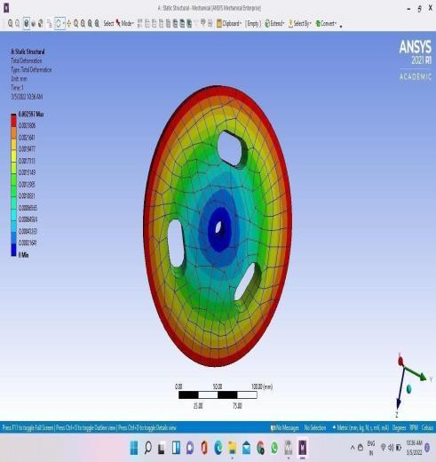
Factordeformationofsafety
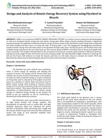
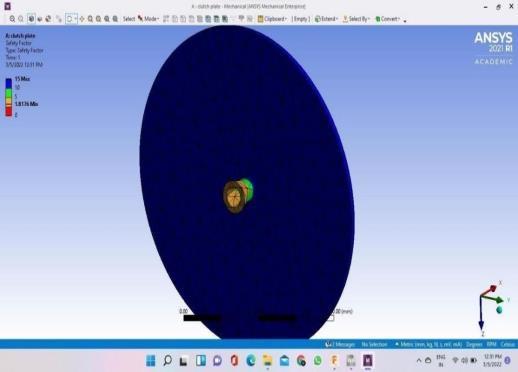
5.2 CLUTCH PLATE:-
Gravitationalforce
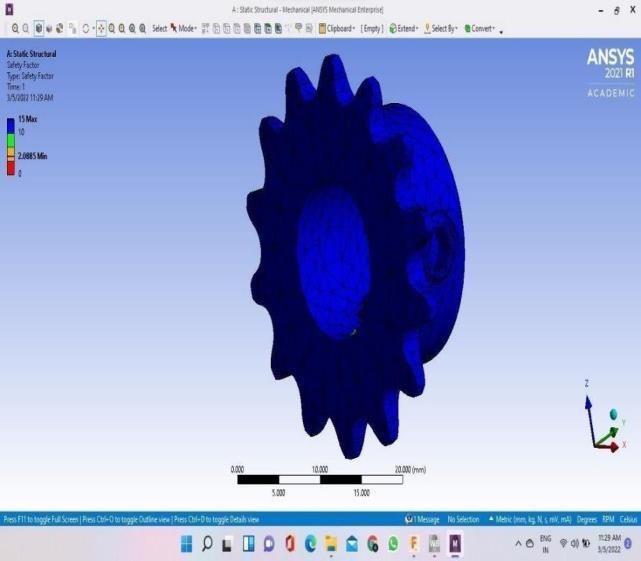
FromFEAanalysiswecanseethat
LoadsactingontheClutch
supportTotal Factordeformationofsafety
1) MinimumFOSofClutchplate=1.8176
International Research Journal of Engineering and Technology (IRJET) e ISSN: 2395 0056 Volume: 09 Issue: 03 | Mar 2022 www.irjet.net p ISSN: 2395 0072 © 2022, IRJET | Impact Factor value: 7.529 | ISO 9001:2008 Certified Journal | Page951
According to the information provided above, the clutch platedesignisperfectlysafe.
2) Maximumdeformation=0.013742mm
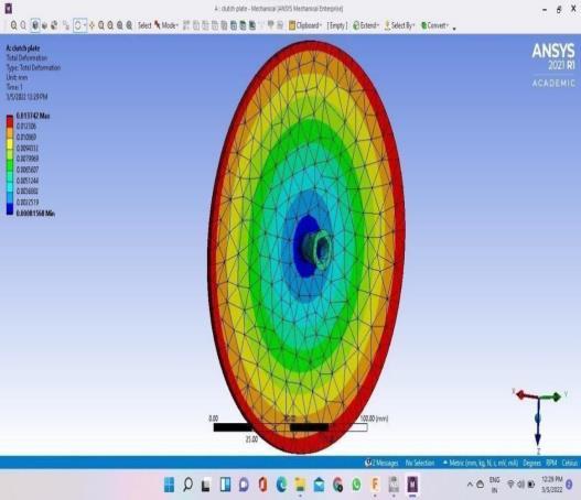
5.3 FRONT SPROCKET:
=55.55rad/sec
The clutch plate is a critical component of KERS. During engagement and disassembly with the flywheel,itissubjecttoanumberofrestrictions.
Total
i) Factorofsafetyofflywheel=15
Rotationalinertialforce
Torque=8.28N m Supports, a) Compressiononlysupport
forceduetoactuationofclutch=435.78
b) Contact
ii) Maximumdeformation=0.002957mm
FromFEAwecanassumethat
Loadsacting, a) Gravitationalforce
The above data suggest that design of flywheel is completelysafe
1) Stainless Steel cylindrical shaft; Outer diameter= 25 mm;
According to the information presented above, the sprocketdesignistotallysafe.
Theclutchdriveismanufacturedinthefollowingmanner. Itscopyismadeinthesamemannerastheoriginal.
b) Rotationalinertiaforce=55.55rad/sec
onlyTotalsupportdeformationFactorofsafety
1. Raw Material:
6.2 CLUTCH DRIVE:
FromFEAwecanassume, i) FOSofSprocket=15
b) Drillingisdoneatthecentralpositionoftheflywheel usinga12mmdrillbit.
a) Thesurfacepolishisachievedbyperformingafacing operationonbothsidesoftheflywheel.
b. Thescribberisusedtomakethemarks.
The following is the manufacturing procedure for each componentcreatedinthisproject: The steps for each component's preparation are as i)follows:Rawmaterialrequirement
International Research Journal of Engineering and Technology (IRJET) e ISSN: 2395 0056 Volume: 09 Issue: 03 | Mar 2022 www.irjet.net p ISSN: 2395 0072 © 2022, IRJET | Impact Factor value: 7.529 | ISO 9001:2008 Certified Journal | Page952
c) Theoutsidediameteroftheflywheelisthenreduced to20cmusingaturningoperation.
2. Machining:
a. Drilling in the centre using an 18 mm drill bit withatoleranceof0.05mm
ii) Maximumdeformation=0.04079mm
6.3 CENTRAL SHAFT:
1)Supports,Compression
6.1 FLYWHEEL;-

1. Raw materials :
2. Machining:
d) To prevent overheating during the turning action, theflywheelisgraspedwiththehelpofatail stock
ii) Machining
d. Ahandcutterisusedtocutthematerial.
1. Raw Materials :
a) Castironcircularsheet;outerdiameter=20cm;Disk thickness=3.5cm
c) Torque=8.28N m
1) EN8 Steel cylindrical shaft; Outer Diameter = 3cm ; Length=5cm
CHAPTER MANUFACTURING6: PROCESS:-
c. Thepurposeofthe facingprocessisto providea smoothsurfacefinish.
e) .After the boring procedure, the hole's diameter is enlargedto20mmwitha0.05mmtoleranceandadepth of0.8mm.
e. Hand grinding is done to remove unwanted materialandmakethesurfacesmooth
f) On the other hand, the identical operations were carriedout.
4) A Variable Inertia Flywheel Model for Regenerative Braking on a Bicycle Proc. ASME. DSCC2014, Volume 2; Dynamics and Control of Wind Energy Systems; Vehicle Energy Management Optimization; Energy Storage, Optimization; Transportation and Grid Applications;; Energy Harvesting, V002T21A004, October22 24,2014
1) Effect of the Ratio Spread of CVU in Automotive KineticEnergyRecoverySystems J.Mech.Des.Jun 2013,135(6):061001
(A) (B) =(B/A)*100EFFICIENCY (%) 233 48 20.6 208 39 18.75 223 44 19.28
3) Energy Based Modeling of Alternative Energy Storage Systems for Hybrid Vehicles Proc. ASME DSCC2011, ASME 2011 Dynamic Systems and Control Conference and Bath/ASME Symposium on Fluid Power and Motion Control, Volume 2, 701 708,October31 November2,2011
ASSEMBLY
2) Design of Kinetic Energy Recovery System for Effi CycleProc. ASME. IMECE2014, Volume 12: Transportation Systems, V012T15A014, November14 20,2014
Accordingtothefindingsofvarioustesting,thesystemis capable of recovering 20% of distributed energy. The KERS system offers a lot of room for improvement and energy savings. The adoption of more efficient methods will result in significant cost savings for our country's economy.WemayinferthatKERSoffersawidevarietyof technical applications for reducing energy loss. These days,conservingenergyiscritical.
International Research Journal of Engineering and Technology (IRJET) e ISSN: 2395 0056 Volume: 09 Issue: 03 | Mar 2022 www.irjet.net p ISSN: 2395 0072 © 2022, IRJET | Impact Factor value: 7.529 | ISO 9001:2008 Certified Journal | Page953
5) D. K. Naresh Kumar, M. Sarath Kumar, S. Murugavel, M. Pradeep, P. Prasath (November 2014) “Design and Fabrication OF Flywheel Bicycle with Mobile Charger”, International Journal of Scientific Research,Volume 3, Issue 11, ISSNNo2277 8179
TheaverageefficiencyoftheKERSis19.54%.TheRPMof rear wheel while storing energy is completely depended onthepayloadsthatweapplied.
CONCLUSIONS:
The observations are taken by using a laser tachometer. The First observation is RPM of rear wheel while energy storingintheflywheel(A).ThesecondobservationisRPM ofrearwheelwhileenergygivenbacktorearwheelfrom theflywheel(B)
References:
a. Turningoperationisdonetoreducethediameter oftheshaftto20mm.
c. Thedistancebetweengroovesmustbe5cm.
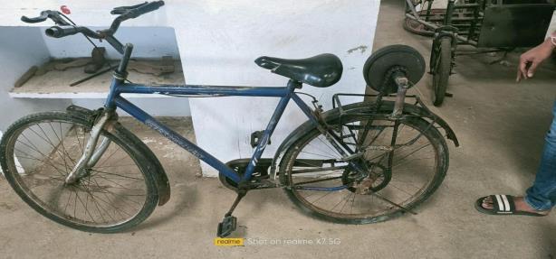
Toimproveefficiency,we'veinstalledtheKERSsystemon a bicycle with an elegant and removable clutch mechanism. Because there are so many mating components in the system, there is a lot of friction damage, which may be reduced by using a continuous variable transmission, which greatly increases power transfer.
2) Length=20.5cm
2.Primary Machining:
b. Grooving operation is done to make grooves of thickness1mm.
FEA analysis is used to test and modify components to prevent failure. The flywheel hasalsobeendiscovered to be a viable alternative to batteries for storing and distributingenergy.
CHAPTER OBSERVATION6: TABLE:
6) Sreevalsan S Menon, Sooraj, Sanjay Mohan, Rino Disney,SuneethSukumaran(August2013