International Research Journal of Engineering and Technology (IRJET) e ISSN: 2395 0056
Dexter : Design, Fabrication, Testing & Validation of a Portable Tabletop Solid Rocket Motor - Static Performance Thrust Stand with a Wirelessly Controlled Data Acquisition System.
b.Study and research of solid rocket motor propulsion systems&preparationofvariouspropellantmixtures.
In a broad sense, in the solid rocket, the fuel and oxidizer aremixedintoasolidpropellantusingappropriatebinders andadditivespackedintoasolidmotorcasingwithvarious grains controlling the burn rate. When the mixture is ignited, combustion takes place on the surface of the propellant producing great amounts of exhaust gases at hightemperatureand pressure. Theamount ofthrust that is produced depends on the motor design i.e classification basedonits(D)diameter,nozzledesign,(Ae/A*)arearatio which accelerates the flow, (Ve) exhaust velocity, fuel, oxidizer used, oxidizer to fuel ratio i.e (MR) mixture ratio, andpropellant(M)Molecularweight,etc.Aftercompletion ofdesign,horizontalorverticalstatictestsofrocketmotors areconductedto evaluateand determine the performance ofpropulsionsystemsrequiredforaerospaceapplications. These tests are fully experimental and instrumented. Physical parameters recorded and calculated are (T) Thrust,(Isp)Specificimpulse,(ṁ)Massflowrate,and(Ve) Exhaust velocity Temperature, pressure, strain, vibration, shock, and acoustic levels can also be measured. The instrumentation sensors used are load cells. Thermocouples, pressure transducers, flow meters, accelerometers,straingauges canalsobeused. Therocket motor is test fired and the data is recorded on data acquisition systems. Detailed analyses are carried out for performanceevaluation.
© 2022, IRJET | Impact Factor value: 7.529 | ISO 9001:2008 Certified Journal | Page924

Key Words : SolidRocketMotor,ThrustStand,(DAQ)Data Acquisition, Design, Fabrication, Static Performance, AnalyticalStudy,ExperimentalTesting.
a.Design&developmentofDexter:portabletabletopsolid rocketmotorstaticthruststandwithwirelessDAQsystem.
Abstract Scientific experimental activities on rocket propulsion being accessible to student researchers is one of the key factors for research and development in the field of aerospace engineering. However, even under the regulatory limits of amateur rocketry, the required rocket motors and their test facilities are unavailable to the majority of institutes in India and other developing countries. Concerning this issue, this paper details the research and development of Dexter, which is a portable tabletop solid rocket motor static performance thrust stand with a wirelessly controlled data acquisition system, built to provide research and development opportunities for students to gain in depth knowledge and practical experience about rocket propulsion systems and advance in the field of aerospace engineering. The development of this project is explained in two phases described as 1. Design & Fabrication & 2. Testing & Validation. The design and fabrication phase presents the technical drawings, CAD models, schematic diagrams, PCB layouts, fabrication materials, techniques, prototypes of the portable tabletop thrust stand, solid rocket motor, wirelessly controlled data acquisition system, and its components. The testing & validationphasepresentsanexperimentalinvestigationofG class solid rocket motor’s static performance, computing the thrust, mass flow rate, and supersonic exhaust velocities through a convergent divergent nozzle over varying propellant mixtures ratios using(C6H14O6) D Sorbitol as fuel and (KNO3) Potassium Nitrate as an oxidizer, performing data visualization and graphical representation through MATLAB Software with a comparative study between the analytical solutions and the experimental results over selected solid rocket motor performance parameters from the testing phase and thus validates the entire project with acceptableerror margins.These errorsanddifficultiesfaced during the project are measured and discussed with the future scope. Conclusions of this project and its importance totheaerospaceresearchcommunityareoutlined.
1. INTRODUCTION
1.1 Research Objectives
Volume: 09 Issue: 03 | Mar 2022 www.irjet.net
p ISSN: 2395 0072
Diameter;W DryWeight;Cp SpecificHeatCoefficient at constant pressure ; Cv Specific Heat Coefficient at constant volume ; Mesup Supersonic Mach Number ; Mesub Subsonic Mach Number ; T0 Stagnation Temperature ; Te Exhaust Temperature ; ff Fuel Mass Fraction ; A Area ; C* Characteristic Velocity ; Ct Thrust Coefficient ; T Thrust ; It Total Impulse ; m Products Mass ; mp Propellant Mass ; ṁ Mass Flow Rate;Isp SpecificImpulse.
Rishabh Naik1, Sarang Mane1 , Yash Salian1, Tanuja Datar1, Aditya Kane1, Tushar Desai1
Nomenclature : Dc CoreDiameter;MR MixtureRatio; Ve ExhaustVelocity;Ae/A* AreaRatio;R Reynolds Number;M MolecularWeight;k SpecificHeatRatio;ρ Density ; f0 Oxidizer Mass Fraction ; Do Outer
1Department of Aerospace Engineering, MIT School of Engineering, MIT ADT University, Pune 412201, Maharashtra, India. ***
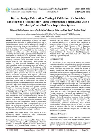
Fig 4:SolidRocketMotorClamp SymmetricalHalf
c.Investigation on propellant performance over variable oxidizertofuelratiosi.e(MR)mixtureratio.
Fig 1:PortableTabletopStaticPerformanceThrustStand
International Research Journal of Engineering and Technology (IRJET) e ISSN: 2395 0056
p ISSN: 2395 0072
2.1 Portable Tabletop Solid Rocket Motor Static Performance Thrust Stand
-
e.Innovation in the field of aerospace engineering to provide research and development opportunities for students to gain in depth knowledge and practical experienceaboutrocketpropulsionsystems.
Volume: 09 Issue: 03 | Mar 2022 www.irjet.net
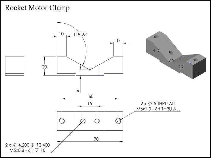
Fig 2:WeightFlowRateLoadCell MountingPlate
© 2022, IRJET | Impact Factor value: 7.529 | ISO 9001:2008 Certified Journal | Page925
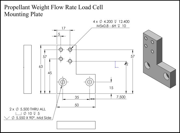
Fig 3:LinearGuideRod cumThrustStandBase
d.Demonstration, visualization, and analyses of overall solidrocketmotorstaticperformanceparameters.
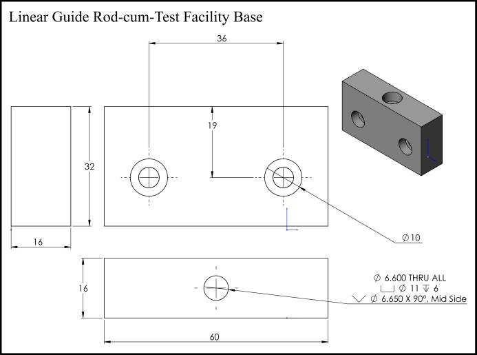
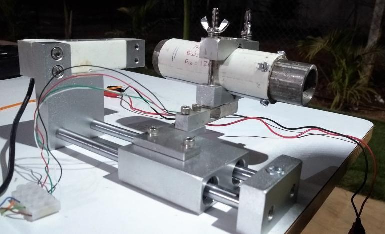
The experimental setup is a self developed portable tabletop thrust stand capable of demonstrating and carrying out static performance tests of solid rocket motors. The setup uses linear guided horizontal force computing methodology to determine the rocket thrust output and a vertical force computing methodology to determine the propellant weight flow rate which simply leads to the determination of the mass flow rate considering the earth’s gravitational acceleration. Both methodologies utilize a single point shear beam load cell. Technical drawings and CAD models are generated on SolidWorks2011fortheassembledportabletabletopsolid rocket motorthruststandas well as itscomponents. Most of the components are fabricated using combinations of lathe,vertical milling,anddrillingmachineoperationsand are assembled using component specific nuts and bolts. Theentirestructureismanufacturedusinghighgradelight weight aluminium & anti corrosive stainless steel. [Fig : 1,2,3,4,5,6,7].
2. DESIGN & FABRICATION
Fig 10:EndCap
Fig 7:ShearBeamLoadCell Thrust&WeightFlow
International Journal of Engineering and Technology (IRJET) e ISSN: 2395 0056
Fig 5:LinearGuidedBlock cumMountingPlateBase
Solidrocketmotorcomprisesofrocketmotorcasingmade up of stainless steel which acts as a combustion chamber and a pressurized vessel, this chamber is coated with readilyavailableportlandcementforinsulationpertaining to its fire and heat resistant properties then filled with solid propellant during the testing phase. One end of the rocketmotorcasingisfittedwithamildsteelendcapwhile the other end houses a mild steel convergent divergent nozzle capable of accelerating pressurized exhausts to highersupersonicspeeds. [Fig:8,9,10,11].
p ISSN: 2395 0072
© 2022, IRJET | Impact Factor value: 7.529 | ISO 9001:2008 Certified Journal | Page926
Fig 8:RocketMotorCasing,EndCap&CDNozzle(CS)
Fig 6:ThrustLoadCell MountingPlate
Volume: 09 Issue: 03 | Mar 2022 www.irjet.net
Research
Fig 9:ConvergingDiverging(CD)Nozzle
2.2 Solid Rocket Motor (G Class)
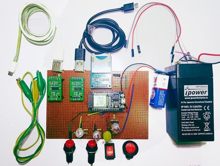
Fig 13:PCBLayout DataAcquisition(DAQ)system
DAQ system accumulates raw data from the load cells & various sensors and processes on it to indicate the final output of experimental data. It takes the analog information through sensors and by using electronic components like micro controller and amplifiers converts ittodigitaloutput.DataisacquiredwirelesslywithaWi fi module i.e. ESP32 which is connected to a Node MCU micro controller.TheschematicsandthePCBdesignofthe system were made on an online PCB design software named EasyEda. The schematic and the PCB include the entire DAQ system along with other subsystems such as Ignition System, Wireless data transmission, and machine control system. [Fig : 12,13]. The data obtained from the experimentispresentedintabulatedformin[Table4].
Fig 14:KNSB PropellantPreparation
p ISSN: 2395 0072
Fig 11:RocketMotorCasing
2.3 Wireless Data Acquisition System (DAQ)
Volume: 09 Issue: 03 | Mar 2022 www.irjet.net
International Research Journal of Engineering and Technology (IRJET) e ISSN: 2395 0056
Fig 12:Schematic DataAcquisition(DAQ)system
2.4 Propellant (Solid)
KNSB is mostly used in experimental rocketry. KNSB Propellant has 35% of D Sorbitol (C6H14O6) as fuel & 65% of Potassium Nitrate (KNO3) as an Oxidizer. The compounds are easily available, it does not contain any toxic element which makes it a safe propellant to do experimentswith.Costisrelativelyless.Thepreparationof fuel is simple & can be done using household appliances. Generally, Sorbitol is a white fine powder and potassium nitrate appears in white crystalline form. Sorbitol and PotassiumNitrateare collected in one vessel. The mixture is heated until caramel is formed, the fuel should not be overcooked and is then filled in the rocket motor casing. CatalystsandAdditivessuchasFerrousOxide,Magnesium and Aluminium powder, etc can be added in calculated proportions up to Max = 5% of the Propellant. [Fig : 14]. The propellant component & mixture chemical data is presentedintabulatedformin[Table:1,2,3].

© 2022, IRJET | Impact Factor value: 7.529 | ISO 9001:2008 Certified Journal | Page927
4. DiameterofNozzlethroat=15mm
EnthalphyofFormation 1353.7kJ/mol 494.00kJ/mol NA
Sorbitol Potassium Nitrate Magnesium
3.1 Combustion Process
Igniter system Pyrotechnic initiator, composition (ZPP) zirconium potassiumperchlorate.Thefollowingigniteris placedattheendofthecombustionchamberneartheend cap. Internal Heat Resistant Insulation is made up of Gypsum, Portland based Cementitious plasters. This prevents the excessive heating & meltdown of the rocket motor.[Fig:15].
Massfractionofcondensedphase 0.436 Ratioofspecificheats 1.1361
7. AreaofThroat=176.625mm2
Molecularform C6H14O6 KNO3 Mg
Density 1.841g/cm3
3.2 Input ParametersParametersofStudy:
1. LengthoftotalRocketmotor(withNozzle)=148mm
Burnrateat1atm 2.6mm/s
8. ExitareaofNozzle=615.44mm2
Density 1.489g/cm3 2.109g/cm3 1.738g/cm3
The chemical equation for the combustion of Potassium NitrateandSorbitolis5O2 +4KNO3 +2C6H14O6 →12CO2 + 4H2O + 2N2 + 2K2CO3.Potassium carbonate is released by the combustion reaction and is neither flammable nor explosive. It has a rating of two for health but since it is hygroscopic,itabsorbswatersoonafteritiscreatedandis therefore diluted and harmless. Similarly, all of the other chemicalsaresafewithhealthhazardratingsofzero
2. DiameterofCombustionchamber=34mm
Combustiontemperature 1327 ℃
Effective molecular weight of exhaustproduct 39.869g/mol
Chemical Parameter KNSB
5. DiameterofNozzleexit=28mm
MolecularWeight 182.172g/mol 101.103g/mol 24.305g/mol
BoilingPoint 296 ℃ 400 ℃ 1091 ℃
Volume: 09 Issue: 03 | Mar 2022 www.irjet.net ISSN: 2395 0072
International Technology (IRJET) e ISSN: 2395 0056
G Class Solid Rocket Motor
3. LengthofCombustionchamber=88mm
6. LengthofNozzle=60mm
p
© 2022, IRJET | Impact Factor value: 7.529 | ISO 9001:2008 Certified Journal | Page928 Table 1: Propellant Component Chemical Properties Table 2: KNSB Propellant Chemical Properties 2.5 Ignition & Insulation Systems Fig 15:ZPPPyrotechnicIgniters
Chemical Parameter
Specificimpulse 164s
MeltingPoint 94 96 ℃ 334 ℃ 650 ℃
Research Journal of Engineering and
Characteristicexhaustvelocity 909m/s
3. TESTING & VALIDATION
0(start) 0.29 120.30(start) 0.05 0.31 119.51 0.14 3.36 118.44 0.24 12.34 117.23 0.34 19.20 116.08 0.44 23.61 114.12 0.53 26.12 111.15 0.63 31.62 106.72 0.73 36.13 104.53
© 2022, IRJET | Impact Factor value: 7.529 | ISO 9001:2008 Certified Journal | Page929
1.7 49.33 49.32
1.31 60.86 93.56 1.41 62.87 86.51 1.51 63.41(max) 73.21 1.6 60.56 60.05
p ISSN: 2395 0072
3.4 Analytical Study & Calculations.
International Research Journal of Engineering and Technology (IRJET) e ISSN: 2395 0056
Table 3: Various Propellant Mixtures Used
0.82 40.79 102.87 0.92 45.12 100.12 1.02 51.89 99.01 1.12 54.77 97.37 1.21 57.72 95.93
g
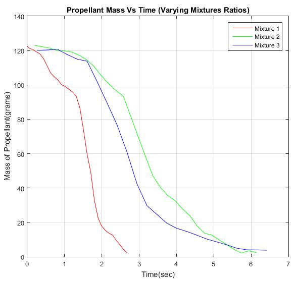
Oxidizer (KNO3) , Fuel (C6H14O6) & Additive (Mg). Mix 1is thebestpropellentmixturewithMR=2.03[Table:3].
NoMix Mass Oxidizerof Mass of Fuel Mass Additiveof RatioMixture
3.5 Experimental Observations
3 66.47g 50.13g 3.7g 1.32
BurnTime=2.67seconds.FuelLeft=0grams
*AnalyticalCalculations(Theoretical)forMix1
1.8 34.1 32.68 1.9 19.2 22.43 1.99 8.36 17.95 2.09 3.57 15.42 2.19 1.92 13.69 2.29 1.39 12.56 2.38 0.49 9.67 2.48 0.31 7.12 2.58 0.33 4.24 2.67(end) 0.06 0(end)
1 78.12g 38.47g 3.7 2.03 1.63
2 72.29g 44.30g 3.7g
Table 4: Thrust vs Time vs Propellant Remaining
3.6 Experiment Setup
Volume: 09 Issue: 03 | Mar 2022 www.irjet.net
SpecificImpulse(Isp)=152.54s
AveragePropellantMassFlowRate≈45g/s
Time Thrust (N) Propellant Mass (g)
*ExperimentalObservations(Measured)forMix1
The entire experimental setup is self developed. The tests were conducted at MIT ADT University. 3 Tests were performed on 8th March 2020. The objective of the experimental setup was to measure the thrust generated,
SupersonicExhaustVelocity(Ve)=1496.48m/s
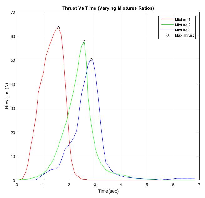
SolidRocketStaticThrust(T)max=63.41N
International Research Journal of Engineering and Technology (IRJET) e ISSN: 2395 0056 Volume: 09 Issue: 03 | Mar 2022 www.irjet.net p ISSN: 2395 0072 © 2022, IRJET | Impact Factor value: 7.529 | ISO 9001:2008 Certified Journal | Page930 propellant mass flow rate, and calculate the supersonic exhaustvelocityalongwithspecificimpulse.[Fig:16,17]. Fig 16:ThrustStand&SolidRocketMotor FinalSetup Fig 17:WirelessDAQSystem FinalSetup 3.7 Final Results & Calculations 1.Thrust(T)max =ṁ×Vemax;[Table4][Fig:18,19,20]. Peak thrust = 63.41 N through experiments, average mass flow rate calculated (ṁ) = 45.00 g/s through experiments Vemax=63.41/45.00/1000;Vemax =1409.11m/s; 2.SpecificImpulse(Isp)=Ve/g0;g0=9.81m/s2 Vemax=1409.11; Isp=1409.11/9.81;Isp=143.64s Fig 18:ThrustvsTime;Mix:1;2;3; Fig 19:PropellantMassvsTime;Mix:1;2;3; Fig 20:ExhaustVelocityvsTime;Mix:1Only
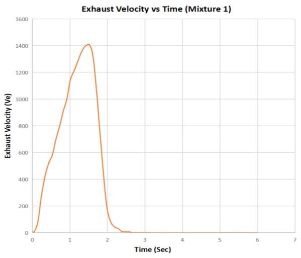
Ve(ExhaustVelocity) 1496.48m/s 1409.11m/s 5.83%
Performance Parameter Analytical Data Experimental Data Percent Deviation
Theauthorsdeclarethattheyhavenocompetinginterests.
© 2022, IRJET | Impact Factor value: 7.529 | ISO 9001:2008 Certified Journal | Page931
Isp(SpecificImpulse) 152.54s 143.64s 5.83%
As the ratio of oxidizer to fuel ratio increases the thrust obtainedalsoincreasesuntiltheoptimumMixtureRatiois achieved. The propellant consumption increases, the mass flow rate increases, the Burn time decreases, and Specific Impulseincreases.HenceMixture1,MRof2.03i.eOxidizer (potassium nitrate) = 66% and Fuel (Sorbitol) = 33% and Additive (Magnesium) serves as the optimum propellant ratio. Thetesting&validationphaseuseMix1asstandard.
International Research Journal of Engineering and Technology (IRJET) e ISSN: 2395 0056
4. CONCLUSIONS
4.2 Error Solutions & Future Scope
SupersonicMachNo 2.4310 2.289 5.83%
Volume: 09 Issue: 03 | Mar 2022 www.irjet.net
instrument sensor errors and noise generated. Take the lossesduetofrictionintoconsiderationandaddthelosses accordingly. Conduct further experiments in a vacuum chamber to remove the environmental oxygen from affectingtheexperimentalresults.
c.AstheOxidizertoFuel ratioreachesoptimumvalue,we see an increase in thrust produced, decrease in propellant consumption with higher supersonic exhaust velocities. Errorsandaccuracyoftheself developedsystemlimitthe experimental results to be exactly equal to the analytical solutionsbutareveryclose.
3.9 Comments & Discussion on the Rocket’s Static Performance over Variable Mixture Ratio (MR)
This research did not receive any specific grant from the MIT ADT University, funding agencies in the public, commercial,ornot for profitsectors.
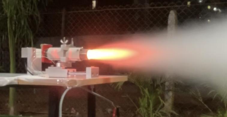
a. As demonstrated in this paper, Dexter, which is a portable tabletop solid rocket motor static performance thrust stand with a wirelessly controlled (DAQ) data acquisition system has been self developed to study, visualizeandanalyzethesolidrocketmotorsperformance characteristicsatascientificlevel.[Fig:21].
3.8 Comparison between Analytical (Calculated) and Experimental (Observed) Results
b.KNSBpropellantusedisoflowcostandanbemadewith readilyavailableingredients. ThestudyofvariousMixture Ratios and their effect on the Solid Rocket Motor performancewassuccessfullydemonstrated.
p ISSN: 2395 0072
e. A futuristic & innovative approach was used to design, fabricate, test & validate a rocket test facility capable of demonstratingpropulsionbasedresearchandexperiments while promoting fellow undergraduate students from multidisciplinary branches to take part in the field of aerospaceengineering.
Theexperimentalresultsarewithintheconsiderablerange of analytical results ( 5.83 % error) & thus proves the authenticityofDexter&theexperiment. [Table:5]
Table 5: Analytical vs Experimental Data
Fig -21:ProjectDexter SuccessfulPrototypeTest
5. FUNDING
To develop a vibration oscillation damping mechanism to overcome the error present in the current mechanism to achievehigheraccuracy.Isolatethecollecteddatafromthe
6. COMPETING INTERESTS
Volume: 09 Issue: 03 | Mar 2022 www.irjet.net
[9] Waugh, Iain & Moore, Edward & Macfarlane, James & Watts, Adam & Jubb, Daniel. (2018). Overview of rocket testing at the Westcott test facility (2016/2017).
[2] Richard Nakka's Experimental Rocketry Website, https://www.nakka rocketry.net/
[8] DAQ NodeMCUhttps://nodemcu.readthedocs.io
[14] Andrade, Emerson & Alves, Wilton & Almeida Prado, André & Martins, Cristiane. (2011). Development of test stand for experimental investigation on of chemical and physical phenomena in Liquid Rocket Engine. Journal of Aerospace Technology and http://dx.doi.org/10.5028/jatm.2011.03021111Management.
REFERENCES
[11] Bacchus, D. L., Hill, O. E., and Whitesides, R. H., “Facility for cold flow testing of solid rocket motor models”, in 1992 JANNAF Propulsion Meeting, 1992, vol.1,pp.353 363.
© 2022, IRJET | Impact Factor
[4] Anderson, John D. Introduction to Flight. New York: McGraw Hill,1985.Print.
p ISSN: 2395 0072 value:
ACKNOWLEDGEMENTS
The authors thank Dr. Sadanand Gokhale & Prof. Dr. Sunil Dingare for their valuable support. The thrust stand was jointlymanufacturedbyRajeshNaik@PrintellAutomation.
International Research Journal of Engineering and Technology (IRJET) e ISSN: 2395 0056
[13] Fedaravičius Algimantas, Račkauskas Saulius, Survila Arvydas,PatašienėLaimaDesignofthetestingsystem for solid propellant rocket motor thrust measurements using mathematical modelling techniques. Journal of Measurements in Engineering, Vol.3,Issue4,2015,p.123 131.
[12] Thomas, James & Stahl, Jacob & Morrow, Gordon & Petersen, Eric. (2016). Design of a Lab Scale Hybrid Rocket Test Stand. 10.2514/6.2016 4965. http://dx.doi.org/10.2514/6.2016 4965
[1] RafaelaBaldissera,MatheusPoletto,SolidPropellants for Rockets: A methodology to Obtain high purity KNO3 from an inexpensive source, 28 08 2018, by IJRET,eISSN:2319 1163,pISSN:2321 7308
7.529 | ISO 9001:2008 Certified Journal | Page932
[6] T. Neff, M. Rehberger and A. Meroth, "Thrust test bench for student rocket engines," 2016 11th France Japan & 9th Europe Asia Congress on Mechatronics /17th International Conference on Research and Education in Mechatronics (REM), 2016, pp.141 30https://doi.org/10.1109/MECATRONICS.2016.75471145,
[7] Umang Jain,Harshit Shukla,Sashant Kapoor,Amit PandeyandHarsh Nirwal."Design and Analysis of 2 axis Rocket Motor Stand for Thrust Vectoring," AIAA 2020 3920.AIAA Propulsion and Energy 2020 Forum.https://doi.org/10.2514/6.2020 3920
[3] Arun Kumar, L. Anjaneyulu, Emerging Trends in Instrumentation in Rocket Motor Testing Over Three Decades, Defence Science Journal, Vol. 65, No. 1, January2015,https://doi.org/10.14429/dsj.65.7949
[5] Soares, Douglas & Teloken, Francisco & Severo, Tiago &Poletto,Matheus.(2018). Development ofa vertical static test bench for amateur rocket engines. International Journal of Advanced Scientific and Technical Research. 5. https://dx.doi.org/10.26808/rs.st.i8v5.0510.26808/rs.st.i8v5.05.
[10] M. J. Williamson and R. W. Lyman, "Analysis of the T 97 Space Shuttle Solid Rocket Motor Test Facility," 1989 American Control Conference, 1989, pp. 2279 2282,https://doi.org/10.23919/ACC.1989.4790568