International Research Journal of Engineering and Technology (IRJET)
e-ISSN: 2395-0056
Volume: 09 Issue: 03 | Mar 2022
p-ISSN: 2395-0072
www.irjet.net
Topological Advancement in DVR; A review Pooja Arya1, Dr. Preeti Jain2 1Department
of Electrical Engineering Department of Electrical Engineering, Jabalpur Engineering College, Jabalpur, Madhya Pradesh, India ---------------------------------------------------------------------***----------------------------------------------------------------------
Abstract – DVR is a very simplest and widely adopted Power Quality (PQ) improvement controller used in distribution system. Modern power system is structured as deregulated one, hence it is utmost important to PQ under various system conditions. DVR is particularly employed to regulate voltage un der the condition of sag/swell in voltage. DVR is a series connected device designed using power electronics element. With the increase in applications, it has undergone to various topological advancements. This paper presents a brief review on such advancement. Comparative analysis of widely adopted DVR topologies also presented in this paper.
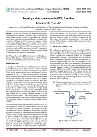
multi-level inverter was preferred to design the DVR architecture, also the control for obtaining reference current for generating gate pulses has the wide research scope [6]. This paper presents the comprehensive reviews on the various DVR topologies available in literature as well as its control architecture. 2. DVR DESIGN AND CONTROL For load voltage regulation and harmonics mitigation DVR as shown in figure 1 is installed near load end. It is a series connected device connected via coupling transformers. It infuses dynamically controlled voltage of appropriate magnitude and phase [7]. From the figure it can be observed that is comprises of coupling transformer to connect the VSI in series with the power line. The VSI is supplied by a DC source generally any battery storage element. The AC output obtained from VSI is contains high number of harmonics, since VSI is a power converter designed using high frequency switches [8]. Therefore, a filter is connected designed using electrical lumped parameters. The voltage across the transformer is the DVR injected voltage which is added to the system in order to maintain load voltage or output voltage at load side [9]. The way in which compensation is provided by DVR is of three categories;
Key Words: Deregulated Market Structure (DMS), Power Quality (PQ), Dynamic Voltage Restorer (DVR), Voltage Source Inverter (VSI), multi-level inverters (MLI). 1.INTRODUCTION In Deregulated Market Structure (DMS), there are multiple entities providing power. Hence one who can provide good quality of power has the inherent advantage of large market share. Hence Power Quality (PQ) management is very important in DMS [1]. The frequent type of PQ issues occurring in distribution system is voltage fluctuation due to sag-or-swell, Flickers and transients. Hence it is mostly employed for regulating voltage at consumer end. The condition voltage sag is arises due to power system faults both short circuit or open circuit faults, due to overloading or due to generation-demand mismatch. Swell in voltage is created due to under loading or removal of high rating power transformer, or high power generation from distributed generation at load side. Both the conditions are very harmful for the voltage sensitive devices or loads connected in the system. They can completely damage the sensitive loads or may leads to system maloperation. Hence it is required to mitigate the condition of sag/swell in voltage (SSV) [2].
1) In-phase compensation: in this case it generates the voltage in-phase with the line voltage as shown in figure 2. VS
|
Impact Factor value: 7.529
VL
Source Side
Load Side Coupling Transformer
Passive Filter
Dynamic Voltage Restorer (DVR) is the preferred choice for mitigating SSV. It is a series connected device interfaced with the system using power converters [3]. It injects the series voltage into the system to remove the voltage difference also it supplies the required the reactive power to mitigate the PQ issues generated due to fluctuations, transients or flickers in system voltages. It also reduces the harmonics generated in the system due to non-linear loading [4]. Due to its increasing popularity, researchers finds a lot of scope to improvise the DVR technology. Conventionally it was designed using 2-level Voltage Source Inverter (VSI) [5]. With the advancement in power electronic applications,
© 2022, IRJET
VINJ
VDC
VSI
Fig -1: Single-line diagram of DVR
|
ISO 9001:2008 Certified Journal
|
Page 865