p
3Professor, Department of Civil Engineering, U.V.C.E, Bangalore University, Bengaluru ***
1P.G Student, Department of Civil Engineering, U.V.C.E, Bangalore University, Bengaluru
Soilstructureinteraction(SSI)isacollectionofphenomena intheresponseofstructurecausedbytheflexibilityofthe foundationsoilsaswellasintheresponseofsoilscausedby the presence of structures. In general, it lengthens, the apparent system period and increases the relative contributionoftherockingcomponentofgroundmotionto thetotal response.Inmany cases,SSIissimplyignored in design without establishing whether it will increase or decrease the response of the structure. Further, soil conditions at a given site may amplify the response of a structure Byneglectingtheamplificationeffectofthesoil where the water tank is located may lead to a lead to an under designedstructureresultinginaprematurecollapse duringanEarthquake
Thedesignofawatertankinaspecificlocationdetermines howmuchwaterisdistributed. waterstorageis generally basedonoverheadwatertankssincetherequiredpressure in the water delivery process is achieved by gravity in elevated tanks rather than the need for large pumping systems.Naturalcalamitiessuchasearthquakes,droughts, floods, and cyclones are all common on the Indian subcontinent. More than 60% of India is prone to earthquakes, according to the seismic code IS:1893(Part 1):2016.Elevatedwatertankshavealargewatermassatthe topofaslenderstagingthatisthemostimportantconcern forthetank'sfailureduringearthquakes.Becauseelevated tanks are often utilized in seismically active areas, their seismic behaviour must be thoroughly examined. Some of thewatertankscollapsedorwereseverelydamagedduetoa
©
|
International Research Journal of Engineering and Technology (IRJET) e ISSN: 2395 0056
Key Words: Dynamic analysis, Soil Structure Interaction (SSI),Sloshing.
|
Abstract Water tanks have been the most vital lifeline structures. They serve as an essential component for most water supply schemes in urban and rural areas. Water storage is generally based on overhead water tanks since the required pressure in the water delivery process is achieved by gravity in elevated tanks rather than the need for large pumping systems. These elevated tanks consist of a large water mass at the top supported by a tall staging which is extremely weak against horizontal forces caused due to earthquakes. The selection of a suitable staging system plays a major role in the behaviour of elevated water tanks during earthquakes since these tanks are often utilized in seismically active regions. The ductility and energy absorbing capacity of such elevated tanks are less compared to conventional building and hence seismic safety of such structures are very important. Soil structure interaction (SSI) is one of the most essential components of structural analysis. This interaction can change the Dynamic characteristics of a structure, which can be advantageous or detrimental to its performance. Conventional fixed base analysis disregards the effect of soil flexibility, resulting in an unsafe design. The present work is focused on the study of seismic response of elevated water tank considering the sloshing effect and to evaluate the behaviour considering Soil Structure Interaction (SSI) effect in seismic Zone (II and III) Different soil conditions are also adopted as per IS1893(Part 2):2014. Modelling and analysis has been carried out using FEM based software SAP2000.
lack of understanding of the supporting system and an incorrect geometrical selection of staging patterns. Liquid storage can take several forms, including underground, ground supported,elevated, andsoon.Municipalitiesand industries utilise liquid storage tanks to store water, flammable liquids, and other materials. As a result, water supplyiscriticalforputtingoutthefirethatmaybreakout duringearthquakes,resultinginpropertydamageandlossof life.Asaresult,watertanksshouldcontinuetoworkinthe aftereffectsoftheearthquake.Thecollapseofawatertanks owingtoseriousdamageinstaging,inwhichnotmeetingthe ductilitycriterionwasoneofcauseobservedintheprevious earthquake. Water tanks also collapsed during the Bhuj (2001) earthquake because of flexural cracks in the shaft type tank staging. Hence seismic safety is utmost concern especiallyinearthquakeproneregions.Theseismicanalysis of elevated tank can be carried out by idealising the structure into two different mass models firstly as per IS: 1893 1984(i.e.,lumpedmassmodel)andsecondlyasperIS: 1893 (Part2)2014(i.e.,twomassmodel).Themotionofthe waterrelativetothetank,aswellasthemotionofthetank relative to the ground, must be included in the dynamic analysis of these tanks. A closed tank is essentially a one massstructurewhetheritisfullofwaterorfullyempty.If thetank hasa free water surface, water will slosh around duringtheearthquake,therebymakingthetankatwo mass structure.Itisstatedthatearthquakesdonotkillindividuals; itisbuildingsthatarepoorlydesignedthatdo.Asaresult, adequateseismicanalysisofthestructureisvital
Jayadeep K. S1, Thejaswini R.M2 , L Govindaraju3
2Assistant Professor, Department of Civil Engineering, G.S.K.S.J.T. Institute, Bengaluru
1.INTRODUCTION
A STUDY ON THE SEISMIC RESPONSE OF ELEVATED WATER TANK
Volume: 09 Issue: 03 | Mar 2022 www.irjet.net ISSN: 2395 0072 2022, IRJET Impact Factor value: 7.529 ISO 9001:2008 Certified
Journal | Page833

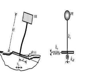
Two mass model: Mostelevatedtanksarenevercompletely filled with water, there is always a free surface for the movementofwaterinsidethetank. Duringearthquakes,due
©
Fig: 1 Tank Model Idealisation
c) Toevaluatedisplacementsandmodalparameters due to soil structure interaction (SSI) in seismic zoneIIandIIIindifferentsoilconditions.
Certified Journal | Page834
to seismic excitation, the liquid in the lower region of the tankbehaveslikeamassthatisrigidlyconnectedtothetank wall which is termed as impulsive mass. The liquid in the upper region of the tank excites with the horizontal acceleration during earthquakes and undergoes sloshing effect(Convectivemass).Henceatwo massidealizationof thetankismoreidealtoaccountsloshingeffectascompared toonemassidealizationwhichisusedinIS1893:1984.Two massModelsforelevatedtankswasproposedbyHousner (1963)whichisusedinmostofinternationalcodes
Liquidsloshingisatypeofwavemotionthatoccurswhena tankispartiallyfull.Intermsofthesafetyofoilandliquefied natural gas transit by sea, the sloshing phenomena are of enormous theoretical and practical importance in coastal andoffshoreengineering.Theliquidinsideapartiallyfilled tankispronetosevereoscillationsandconsiderableimpact pressureonthetankwhenexternalexcitationsareoflarge amplitudeornearthenaturalfrequencyofsloshing.
1: Details of Structural Elements of Elevated Tank Sl.no Contents Dimension 1 Stagingheight 6m 2 Depthofwatertank 3m 3 Freeboard 0.3m 4 Column 300mmx300mm 5 Beam 300mmx400mm 6 Floorslab 180mm 7 Walls 180mm 8 Bracing 300mmx300mm
p ISSN: 2395 0072 2022, IRJET Impact Factor value: 7.529 9001:2008
b) To evaluate response parameters such as base shear, base moment, Displacements and Modal PeriodandFrequencies.
|
1.4 Methodology:
Table
1.5 Problem statement: An RC open square water containerof3mx3mx3m(includingfreeboardof0.3m)is considered.Thetankissupportedonastagingofheight6m above ground level. The depth of the foundation is 1.5m belowgroundlevel.GradeofconcreteandsteelareM25and Fe500,respectively.Densityofconcreteis25KN/m3 .
Volume: 09 Issue: 03 | Mar 2022 www.irjet.net
International Research Journal of Engineering and Technology (IRJET) e ISSN: 2395 0056
b) Two Massmodel(IS1893(part2):2014)
(a)Lumpedmassmodel (b)Twomassmodel
Elevated water tanks can be analysed by idealising the structureintotwodifferentmassmodels
| ISO
The scope of the study is to observe the response of the elevated water tank when subjected to seismic effect considering the effects of SSI. Further, the behaviour of watertankwhenrestingondifferentsoilconditionssuchas soft, medium, and hard during seismic actions need to be observed. Since sloshing phenomena increases severe oscillations,sloshingeffectisalsoconsidered.
d) Torestrictstagingdisplacementundertheallowed limitof(H/500).
a) Lumpedmassmodel(IS1893:1984)
1.2 Scope of the study:
1.3 Objectives of the Present study:
1.1 Sloshing:
a) To perform dynamic analysis using the Response spectrummethod.
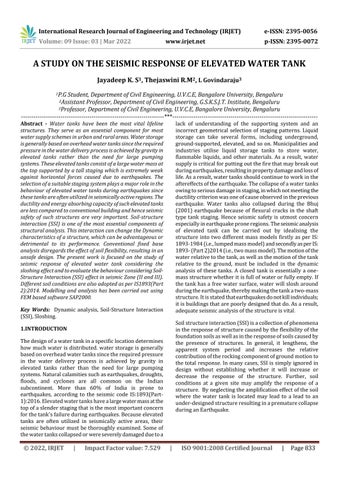
Lumped mass model: It is also called the single mass model.Consideringthis analysismethod,thetankscanbe idealised as a single degree of freedom system where the massisassumedtobeconcentratedatthecentreofgravity ofthetank.Theidealisationofwatertanksasasystemwith asingledegreeoffreedom(i.e.,Lumpedmassmodel)canbe consideredwhenthetanksarecompletelyfilledwithwater or when it is empty. Elevated tanks are never filled completely and hence this model fails to account for the sloshing of water. Hence the tanks can be analysed consideringitaslumpedmassonlywhenitisfullyfilledor empty.
Softsoil 23.40 154.61 32.69 210.08
Softsoil 14.63 96.63 20.43 131.30
Modal 1 0.375 2.66
Certified Journal | Page835
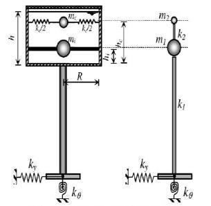
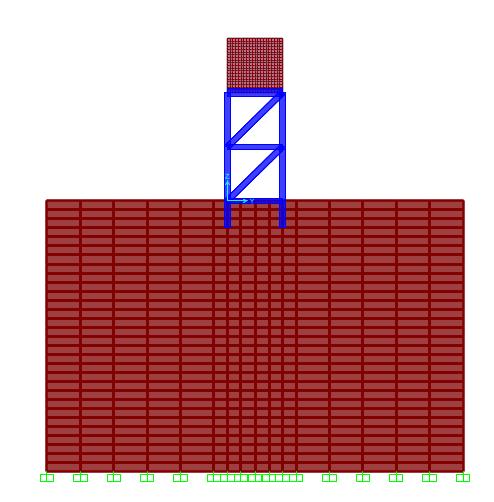
Infixedbaseanalysisthefixityisconsideredattheground level and response spectrum method is carried out considering the different zones (Zone II and Zone III) and response spectrum curve is generated for different soil conditions Figure2displaysthefixedbasecondition.
5 ResponseReductionfactor 4
Table 5: Modal period & Frequencies for Empty tank condition
3
ConvectivePressure (kN/m2) 0.2407 0.3853
Sl.no Contents Description
CaseOutput NoMode (Secs)PeriodTime (FrequenciesCyc/Sec)
International Research Journal of Engineering and Technology (IRJET) e ISSN: 2395 0056
2 Seismiczone II&III Zonefactor 0.10&0.16
Modelling and analysis has been carried out using FEM basedsoftwareSAP2000.Twoparameterswereconsidered in the present study namely fixed base and flexible base (SSI).
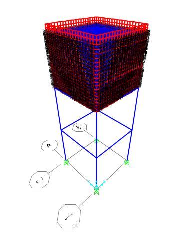
Table -2: Dynamic characteristics of elevated water tank
6 Soiltype I,II&III
p
Zone TypeSoil Empty Tank condition Full Tank condition (KN)ShearBase M)tMomenBase(KN (KN)ShearBase (KNMomentBaseM)
c) TheparameterssuchasBaseshear,Basemoment, Displacement and Modal Parameters are considered.
Impulsivepressure (kN/m2) 0.8536 1.367
Table 4: Base Shear and Base Moment
| ISO
Hydrostatic pressure (kN/m2) 26.487
a) TheEmptytankanalysisiscarriedoutconsidering thedeadloadofthestructure.
|
III Hardsoil 23.40 154.61 28.91 185.77 soilMedium 23.40 154.61 32.69 210.08
Volume: 09 Issue: 03 | Mar 2022 www.irjet.net ISSN: 2395 0072 2022, IRJET Impact Factor value: 7.529 9001:2008
1 Structure SMRF
2.1 Fixed Base Analysis
Fig: 2 Fixed Base Model with water Pressures
©
4 Importancefactor 1.5
II Hardsoil 14.63 96.63 18.07 116.11 soilMedium 14.63 96.63 20.43 131.30
b) TheFulltankanalysisiscarriedoutconsideringthe deadloadofthestructureandHydrostatic(water) load.
Table -3: Water pressure details
Water Pressure Zone II Zone III
2. Modelling and Analysis & Results
Modal 1 0.452 2.210
|
(Sa/g)=2.5for0.10s<T<0.40s(Hardsoil)
Soil Structure Interaction:
Table -8: Displacement for Empty tank condition (m)Height ZoneDisplacement(mm)II ZoneDisplacement(mm)III
0.10s<T<0.55s(Mediumsoil) 0.10s<T<0.55s(softsoil)
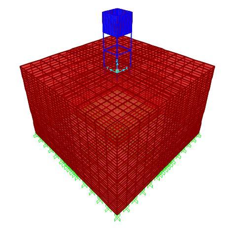
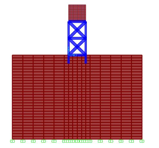
TheResponseofthestructureevaluatedconsidering fixed base model neglecting the effect of soil structureinteraction(SSI)mayalterthebehaviourof thestructureinreal timeandconsequentlymaybe beneficial or detrimental to the performance of structures. So, in the present study, a comparison between fixed base analysis and flexible base (SSI) analysis is done. In this present work, actual soil condition is modelled and analyzed for earthquake conditions as shown in Fig.3. Parameters such as displacementandmodalperiodandfrequenciesare compared.
(a) The Base shear, Displacement, Modal period, and frequencies obtained from the analysis for two seismic zones for empty tank and Full tank conditionsaretabulated
(e) InfulltankconditiontheBaseshear,Basemoment anddisplacementinrespectivezonesarehigherin softandmediumsoilconditionsbutlessinhardsoil conditions.
©
3
Hardsoil 18 95000 0.3 16 35000 0.4
(ElasticitykN/m
Softsoil 16 15000 0.4
CaseOutput NoMode (Secs)PeriodTime (FrequenciesCyc/Sec)
Modal 2 0.452 2.210
Modal 3 0.292 3.422
(b) Thetimeperiodfortheemptytankis0.375s.
Volume: 09 Issue: 03 | Mar 2022 www.irjet.net p ISSN: 2395 0072 2022, IRJET Impact Factor value: 7.529 ISO 9001:2008 Certified
Table 6: Modal period & Frequencies for Full tank Condition
9
(c) The width of soil is 10m on either side and the depthof15misconsidered.
Fig: 3 Soil Structure interaction Model
Table -7: Displacement for Full tank condition (m)Height ZoneDisplacement(mm)II ZoneDisplacement(mm)III soilSoft mMediusoil soilHard soiltSof mMediusoil soildHar 2.6 2.6 2.3 4.1 4.1 3.7 6 2.5 2.5 2.1 4 4 3.6 1.2 1.2 1.1 2 2 1.8 Base 0 0 0 0 0 0
(c) ThetimeperiodfortheFulltankis0.452s.
Modal 2 0.375 2.66
Table -9: Soil properties (Analysis and design of substructures Swami saran)
International Research Journal of Engineering and Technology (IRJET) e ISSN: 2395 0056
|
9 1.9 2.9 6 1.7 2.8 3 0.9 2.4 Base 0 0
(d) Thebaseshear,basemomentanddisplacementare samefordifferenttypesofsoils(Hard,Medium,and softsoil)inrespectiveseismiczonesforemptytank condition, this is due to the same average accelerationcoefficient(Sa/g)
Journal | Page836
Modal 3 0.262 3.80
soilMedium
(a) Isolatedsquarefootingofdepth500mmisprovided at1.5mbelowgroundlevel.
) Poisson’s (µ)Ratio
Soil Type of 2
(WeightUnitkN/m3) Modulus
(b) ThesoilismodelledusingfiniteElementsoftware SAP2000.
|
CaseOutput NoMode (Secs)PeriodTime (FrequenciesCyc/Sec)
Journal | Page837
Modal
Modal 3 0.732 1.365
Table 13: Modal period & Frequencies for Empty tank condition
International Research Journal of Engineering and Technology (IRJET) e ISSN: 2395 0056
©
(a) Hard soil:
Modal 1 1.276 0.783 2 1.276 0.783 3 1.118 0.894
Chart 2: Displacement v/s Height of tank resting on medium soil.
(b) Medium soil:
Modal 1 0.836 1.195 Modal 2 0.836 1.195
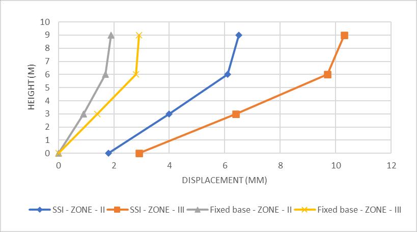
Height(m) ZoneDisplacementII Zone III 9 6.5 10.3 6 6.1 9.7 3 4 6.4 Base 1.8 2.9
|
Fig: 4 Elevated tank with isolated square footing
Empty Tank condition: (a) Soft soil:
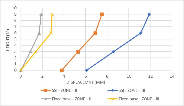
Chart 1: Displacement v/s Height of tank resting on soft soil.
Table 11: Modal period & Frequencies for Empty Tank Condition
CaseOutput Mode No (Secs)PeriodTime (FrequenciesCyc/Sec)
Table 14: Displacement for Empty tank condition
Modal
Volume: 09 Issue: 03 | Mar 2022 www.irjet.net ISSN: 2395 0072 2022, IRJET Impact Factor value: 7.529 ISO 9001:2008 Certified
Table -12: Displacement for Empty tank condition Height(m) ZoneDisplacement(mm)IIZone III 9 7.5 11.9 6 6.9 11.1 3 5.3 8.6 Base 3.8 6.1

p
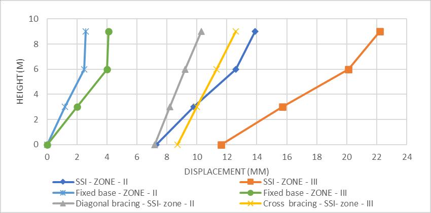
(d) Graphs are plotted to show displacement comparisonbetweenfixedandflexiblebases. (e) Thedisplacementofthestaginghastoberestricted toaratioof(H/500)i.e,12mm.
Table 10: Displacement for Empty tank condition Height(m) ZoneDisplacement(mm)IIZone III 9 11.8 18.9 6 10.7 17.2 3 8.9 14.2 Base 7.1 11.4
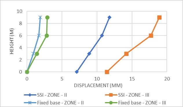
Chart 4: Displacement v/s Height of tank resting on soft soil
Volume: 09 Issue: 03 | Mar 2022 www.irjet.net ISSN: 2395 0072 Factor value: 7.529 9001:2008
| ISO
CaseOutput NoMode (Secs)PeriodTime (FrequenciesCyc/Sec)
Displacement
p
Table -17: Modal period & Frequencies for Full tank condition
Certified Journal | Page838
(m)Height BraceswithoutZoneDisplacement(mm)IIZoneIIDiagonalBracing(300mmX300mm) Zone BraceswithoutII Zone II mm)X(300mmBracingCross450 9 13.9 10.3 22.2 12.6 6 12.6 9.2 20.1 11.3 3 9.8 8.2 15.7 10 Base 7.3 7.2 11.6 8.7
Table
Chart 2: v/s Height of tank resting on Hard soil
International Research Journal of Engineering and Technology (IRJET) e ISSN: 2395 0056
Fig: 5 Elevtaed tank with Diagonal bracing
© 2022, IRJET | Impact
Modal 1 0.535 1.866 Modal 2 0.535 1.866 Modal 3 0.455 2.197
Full Tank condition: (a) Soft soil: 16: Displacement for Full tank condition
Modal 1 1.279 0.781 Modal 2 1.279 0.781 Modal 3 1.118 0.894
CaseOutput NoMode (Secs)PeriodTime (FrequenciesCyc/Sec)
Table -15: Modal period & Frequencies for Empty tank condition
p
CaseOutput NoMode (Secs)PeriodTime (FrequenciesCyc/Sec)
Modal
Modal
7 Base
Volume: 09 Issue: 03 | Mar 2022 www.irjet.net ISSN: 2395 0072 Factor value: 9001:2008
9
Research Journal
Fig: 6 Elevtaed tank with Cross bracing (b) Medium soil: Table -18: Displacement for Full tank condition (m)Height ZDisplacement(mm)oneIIZoneIIIZone II (300mmBracingCross X 450 mm) 8.9 14.2 9 8.2 13.2 8 9.7 3.9 6.2 6.1 19: Modal period & Frequencies for Full tank condition
CaseOutput NoMode (Secs)PeriodTime (FrequenciesCyc/Sec) Modal 1 0.839 1.190 Modal 2 0.839 1.190 Modal 3 0.732 1.365
Certified Journal | Page839
Modal 1 0.548 1.823 2 0.548 1.823 3 0.491 2.035
6
Table -20: Displacement for Full tank condition Height (m) ZoneDisplacement(mm)IIZone III 9 7.9 12.1 6 7.2 11 3 4.6 7.2 Base 2.1 2.8
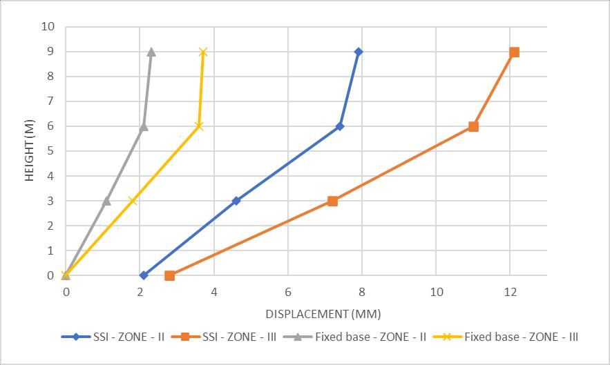
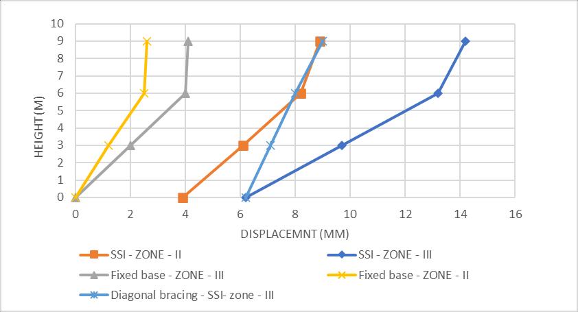
Table 21: Modal period & Frequencies for Full tank condition
Table
Engineering and
International of Technology (IRJET) e ISSN: 2395 0056
3 6.1
7.529 | ISO
Chart 5: Displacement v/s Height of tank resting on medium soil.
(c) Hard soil:
© 2022, IRJET | Impact
Chart - 6: Displacement v/s Height of tank resting on Hard soil.
Hardsoil 0.244 0.3
| ISO
©
Mediumsoil 0.138 0.3
compared with fixed base analysis due to soil flexibility,henceSSIneedstobeconsidered.
b) Afreeboardofheight0.3misprovided.
5. IS 1839 (Part 2): 2014 Criteria for earthquake resistant design of structures. (Liquid retaining tanks).
p ISSN: 2395 0072 2022, IRJET Impact Factor value: 7.529 9001:2008
6. IS 1893 (Part 1): 2016 Criteria for earthquake ResistantDesignofstructures.(Generalprovisions andbuildings).
BIOGRAPHIES:
Certified Journal | Page840
2. Freeboardheightof0.3missufficientforsloshing wave height in Zone II and Zone III and the tank mustberedesignedforZoneIV&ZoneV.
9. TheSSIeffecthasincreasedthetimeperiodofthe structure by 3 times in soft soil conditions when comparedtofixedbasetimeperiod
Mediumsoil 0.2214 0.3
2. Chandrasekaran,A.R.,Krishna,J.,“Watertowersin seismiczones”.In:ProceedingsoftheThirdWorld Conference on Earthquake Engineering, New Zealand,vol.IV,pp.161 171,195.
Table 22: Sloshing wave height in different seismic zones
e) Theprovidedfreeboardof0.3misnotsufficientin zone IV and V and the tank has to be redesigned withahigherfreeboard.
3. IITK GSDMA(2007).“Guidelinesforseismicdesign of liquid storage tanks”, National Information CentreforEarthquakeEngineering,IITKanpur.
1. Base shear in full tank condition is higher than emptytankconditionduetoabsenceofwater
JAYADEEP K.S P.G Student, Department of Civil Engineering, U.V.C.E, Bangalore BengaluruUniversity,JnanaBharathiCampus,560056.

|
Hardsoil 0.1017 0.3
Hardsoil 0.366 0.3
International Research Journal of Engineering and Technology (IRJET) e ISSN: 2395 0056
Mediumsoil 0.498 0.3
c) Thesloshingwaveheightincreasesastheseismic zonechangesfromIItoV.
d) Thefreeboardof0.3missufficientinseismicZoneII andzoneIIIforallthesoilconditionsandforhard soilforseismiczoneIV.
5. Thesoilstructureinteraction(SSI)showincreasein values of displacement and Time period when
Hardsoil 0.162 0.3
Mediumsoil 0.332 0.3
II Softsoil 0.1689 0.3
Zone Soil Type (m)heightwaveSloshing (m)Freeboard
Volume: 09 Issue: 03 | Mar 2022 www.irjet.net
V Softsoil 0.612 0.3
4. Thetotalbaseshearandbasemomentinfulltank conditionaremorethanthattotalbaseshearand basemoment in emptytank condition, the design willbegovernedbyfulltankconditions.
IV Softsoil 0.407 0.3
3. Time period and displacement are higher in full tank conditionduetothepresenceofwater
6. Themaximumdisplacementincreaseswithseismic zones and maximum displacement is observed in softsoils.
8. In soft soils the displacement values are higher compared to medium and hard soils and use of bracingsarerecommendedinsoftsoilsonly.
7. The maximum displacement shall not exceed (H/500), but in soft soils the displacements have exceeded permissiblelimitsanddifferentBracing systems are adopted to limit the displacement values.
III Softsoil 0.2718 0.3
REFERENCES:
1. Housner G W (1963) “The Dynamic Behaviour of WaterTanks”.BulletinoftheSeismologicalsociety ofAmerica,53(2),381 387.
4. IS:3370(Part I) 1965codeofpracticeforconcrete structures for the storage of liquids. (General requirements).
CONCLUSIONS:
a) The sloshing wave heights for different zones in differentsoilconditionsarecalculated.
©
International Research Journal of Engineering and Technology (IRJET) e ISSN: 2395 0056
Volume: 09 Issue: 03 | Mar 2022 www.irjet.net p ISSN: 2395 0072 2022, IRJET Impact Factor value: 7.529 | ISO 9001:2008 Certified
Journal | Page841
Thejaswini R. M.
Assistant professor in Govt. S.K.S.J.T.I Research scholar, Department of Civil Engineering, U.V.C.E, Bangalore University, Bengaluru
L. Govindaraju
Professor, Department of Civil Engineering, U.V.C.E, Bangalore BengaluruUniversity,JnanaBharathiCampus,560056.

|
