International Research Journal of Engineering and Technology (IRJET)
e-ISSN: 2395-0056
Volume: 09 Issue: 03 | Mar 2022
p-ISSN: 2395-0072
www.irjet.net
Measurement of Variable AC Voltage through PLC N Vinay Saketh https://orcid.org/0000-0002-3127-9281, Senior Electrical Engineer, M/s. Entek Technical Services, Hyderabad, India ---------------------------------------------------------------------***---------------------------------------------------------------------Abstract - In Solar Projects and Building Automation Projects the key element is integration of mains supply with solar and diesel generator power supply. Programmable Logic Controllers (PLC) are light-weight, low-cost and self-contained electronic apparatus for a wide range of industrial automation applications, these are widely used to control a simple, repetitive tasks [1]. In this paper we will build circuit, simulate and implement AC Voltage measurement using PLC. Many multi-meters and volt-meters use the same voltage divider to reduce the voltage to safe measuring voltage. Application for this circuit is Energy Management, Building Automation, Smart APFC Panel and Solar Projects. Key Words: Analysis, EMI, Flux Density, Quick Field Software, Insulation.
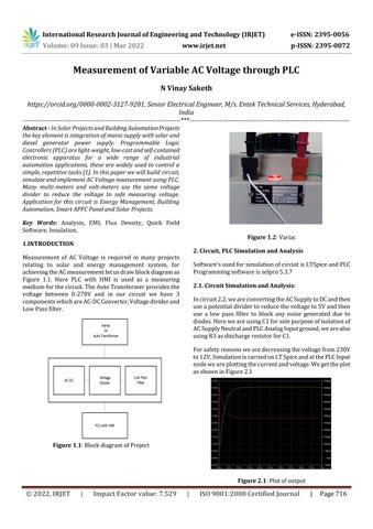
Figure 1.2: Variac
1.INTRODUCTION
2. Circuit, PLC Simulation and Analysis
Measurement of AC Voltage is required in many projects relating to solar and energy management system, for achieving the AC measurement let us draw block diagram as Figure 1.1. Here PLC with HMI is used as a measuring medium for the circuit. The Auto Transformer provides the voltage between 0-270V and in our circuit we have 3 components which are AC-DC Converter, Voltage divider and Low Pass filter.
Software’s used for simulation of circuit is LTSpice and PLC Programming software is selpro 5.3.7 2.1. Circuit Simulation and Analysis: In circuit 2.2, we are converting the AC Supply to DC and then use a potential divider to reduce the voltage to 5V and then use a low pass filter to block any noise generated due to diodes. Here we are using C1 for sole purpose of isolation of AC Supply Neutral and PLC Analog Input ground, we are also using R3 as discharge resistor for C1. For safety reasons we are decreasing the voltage from 230V to 12V, Simulation is carried on LT Spice and at the PLC Input node we are plotting the current and voltage. We get the plot as shown in Figure 2.1
Figure 1.1: Block diagram of Project
Figure 2.1: Plot of output
© 2022, IRJET
|
Impact Factor value: 7.529
|
ISO 9001:2008 Certified Journal
|
Page 716