The system's analogue to digital converter receives the analoguesignalofthefluidlevelsensedbythesensorand converts it to a digital 5 value, which is then passed on to the Themicrocontroller.digitalsignalindicating the fuel level in the bottle is received by the microcontroller. At the same time, the microcontroller compares the signal value to a threshold level. When the sensor's value goes below a pre determined threshold, the Microcontroller sends two signals: one to the buzzer and the other to the GSM Themodule.fluidorelectrolytethatisscheduledtobegiventothe patient will be contained in the saline bottle. This saline container will have a liquid level sensor 2 added to it to
Soundwavesareusedbyflowratesensorstoestimatethe flow rate of fluid passing through a pipe. However, this sensor can be used because the flow rate is slow and precisebecauseitisintheformofdroplets.
Key Words: GSM, Alert system, Saline Bottle, Health, Bio Medical 1. INTRODUCTION When we realised that we needed to manually monitor fluidlevelsonaregularbasis,wecameupwiththisnotion for innovation. However, due to the health care professional's hectic schedule, they may forget to change or refill the bottle at the appropriate time. As a result, patients'livesmaybecompromisedbecauseairbubblesor blood backflowmay enterthe bloodstream, both of which can lead to patient death. As a result, by eliminating the need to manually monitor fluid levels on a regular basis, this innovation will be tremendously valuable in enhancingthehealth caresystem.
The fluid level of the bottle is measured using a load cell. It's a sort of transducer that converts its load induced deflection into an electrical quantity. The electrical signal varies accordingly as the fluid level drops. When the patient moves their hand, the signals fluctuate. The value of its output is fleeting. As a result, we discarded this Anothersensor.optionistouseaninfraredsensor,whichmaybe used as both a transmitter and a receiver. Some of the radiation emitted by the IR transmitterreaches the object and is reflected back to the IR receiver. The sensor's output is determined by the intensity of the IR receiver's reception.BoththeIRtransmitterandtheIRreceivermust beproperlyenclosedinordertoeliminatereflectionsfrom items other than the target, which is not suitable with a standardsalinebottle.TheineffectivenessofIRsensorsun thiscaseisduetotheirlowsensitivity.
2. Working of the Invention 2.1 Detailed Description of the Invention
UG student Department of Biomedical Engineering, U.V. Patel College of Engineering, Gujarat, India Abstract Hospital employees and health professionals areunderasignificantlotofstressandstraininpandemic scenarios.Thepurposeofthisinventionistoeliminatethe requirement for the nurse to monitor the fluid level on a regularbasis.Thisinventionisabuilt inalarmsystemthat monitors the levels of saline or electrolyte bottles provided to patients. It uses a non contact capacitive switch sensor to detect if the fluid level falls below a predetermined level. The sensor talks with the microprocessor, which then sends a text message and makesaphonecalltoaspecifiednumbertonotifythem.If someone is present in the room, a buzzer will be placed near the patient's bed to alert them. This saves time and prevents medical errors from occurring if the saline or electrolytebottleisn'treplacedorreplenishedontime.
International Research Journal of Engineering and Technology (IRJET) e ISSN: 2395 0056 Volume: 09 Issue: 03 | Mar 2022 www.irjet.net p ISSN: 2395 0072 © 2022, IRJET | Impact Factor value: 7.529 | ISO 9001:2008 Certified Journal | Page53 Bio-Medical Smart Saline Bottle KOSHTI VISHAKHA ASHISHBHAI1 , SHAH BANSARI JIGNESHBHAI2 , BHATT FALGUN PINAKIN3 , PATEL DHRUV JAGDISHBHAI4 , RAVAL NISARG MAHESHBHAI 5 , SHAH NEEL VIRAL6 1 6

***
The following is a description of one of the present invention's specific embodiments. Data acquisition, microcontroller, wireless communication system, and alarm system are the four key components of the present Theinvention.noncontact liquid level sensor that is affixed to the outersurface of the medicinal fluiddelivery bottleisused for data collecting. To perform non contact fluid level sensing, the sensor employs modern signal processing technologies. The sensor is used to keep track of the amount of fluid in the bottle at all times. When the liquid level surpasses a specified threshold, the sensor produces averyaccurateandstablesignal.
Ultrasoniclevelsensorsuseultrasonicwavestodetermine the level of fluid in a bottle. The sensor sends out an ultrasonicpulsethatisreflectedbacktoitbythetarget.It is inserted in the bottom of a saline bottle, which is inconvenientbecauseitnecessitatesbottlemodification.
The Arduino Nano 4 is a small, comprehensive, and breadboard friendly board with an ATmega328 microcontroller(ArduinoNano3.x).It'san8 bitcontroller that runs on 5V. The ADC 3 is attached to the Arduino Nano 4. It will receive digital signals from ADC 3; when liquidisavailable,itwillcontinuetoreceiveaHIGHsignal, and when a LOW signal is received, Arduino Nano will send a signal to GSM module 8 to make a call or send a message. The buzzer 7 is also linked to the Arduino Nano 4, which receives the signal and buzzes to generate a Switchwarning.5isusedtoturnthe systemonandoff, preventing thebatteryfrombeingdepletedineffectivelywhileitisnot in Theuse.system is powered by a rechargeable battery number six.TheArduinoNano4willbeusedtorechargeit.
show the level and alert you if it drops below a particular Thethreshold.saline container is coupled to a non contact liquid level sensor 2 for continuous fluid level monitoring. It works by varying capacitance as a function of the water/liquid. In the absence of liquid near the sensor, distributed capacitance will exist, resulting in some static capacitance to ground on the sensor. As the amount of liquid near the sensor increases, the parasitic capacitance oftheliquidiscoupledtothestaticcapacitance,increasing the sensor's final capacitance value. The changed capacitancesignalistheninputtothecontrolICforsignal conversion,whichconvertsthevariedcapacitanceintothe amountofchangeintheelectricalsignal Finally,whenthe amount of change exceeds a specified threshold, which signifies the liquid level has reached the induction point, the25degreeofvariationcanbecomputedusingacertain algorithm. When the fluid level exceeds a defined point, a HIGHsignalandaredlightwillcontinuetobegenerated.
4 is connected to GSM modem 8. It will receive a signal to send an alarm SMS to the program's specified number. It will also phone the supplied number foranalert. Therewill beanotherdeviceinto whicha simcardcanbe inserted, the number of which will be specified in the ArduinoNano4programme.So,ifanalarmisrequired,an SMSandaphonecallwillbereceivedonthisdeviceviathe sim Thecard.primary goal of the current invention is to notify medical personnel, such as nurses or doctors, as well as thepatient'sfamily,whenthefluidsupplyingtothepatient from the medical bottle is likely to run out. As a precaution, a buzzer is installed at the patient's bedside, which emits a buzz sound as soon as the sensor's value goes below the threshold value. This number will notify family members to notify the nurse about the fluid level conditions.Intheevent that no one is present near the patient, the systemincludesaGSMmodulewitharegisteredSIMcard. Themicrocontroller'sdigitaloutputissuppliedtotheGSM module, which sends a text message containing the room number and the patient's name. In the event that the medicalprofessionalshavenotreadthemessage,theGSM modulewillphonethem.
ArduinoNano4iscoupledtoBuzzer7.Whenitreceivesa signal,itwillemitabuzzingalert. GSM stands for global system for mobile communication and is a mobile communication modem (GSM). A GSM modem is a device that allows a computer or any other processortointeractviaa network.Itcanbeaphoneora modem.AGSMmodemrequiresa SIMcardandrunsona networkrangethathasbeensubscribedtobythenetwork Arduinooperator.Nano
International Research Journal of Engineering and Technology (IRJET) e ISSN: 2395 0056
The non contact liquid level sensor 2 is connected to ADC 3, which will receive an analogue signal based on capacitance fluctuation. This ADC 3 will convert the analogue signal to a digital signal, which will then be transferredtotheArduinoNano4.
2.2 Arduino R3 Code[3] #include<SoftwareSerial.h> SoftwareSerialmySerial(10,11); charmsg; charcall; intMakeCallCount=0; intSendMessageCount=0; constintFluidSensor=3; constintbuzzer=6; voidsetup() pinMode(buzzer,mySerial.begin(9600);{pinMode(FluidSensor,INPUT);OUTPUT);
© 2022, IRJET | Impact Factor value: 7.529 | ISO 9001:2008 Certified Journal | Page54
Volume: 09 Issue: 03 | Mar 2022 www.irjet.net p ISSN: 2395 0072
Capacitancewillvaryandtheredlightwillswitchoffifthe liquidlevel fallsbelowa predefinedlevel.Thissensor will be connected to ADC 3, which will receive an analogue signalbasedoncapacitancefluctuation.
HIGH&&MakeCallCount== 1 && SendMessageCount == 1) //Check the sensor SSendMessageCountMakeCallCount//Fluid_high_Count++;output{=0;=0;erial.println("i'msafe");}
//Sets the GSM Module inText delay(1000);Mode//Delayof1000millisecondsor1second mySerial.println("AT+CMGS=\"+xxxxxxxxxxxx\"\r"); // Replacexwithmobilenumber delay(1000);SendMessageCount++;mySerial.println((char)26);//delay(100);ReplacemySerial.println("yyyyyyyyyyyyyyyyyyyyyyyyy!!!!!!!!");//delay(1000);ywithTheSMStextyouwanttosendASCIIcodeofCTRL+Z}
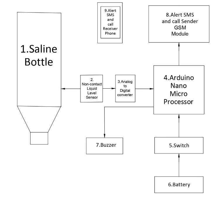
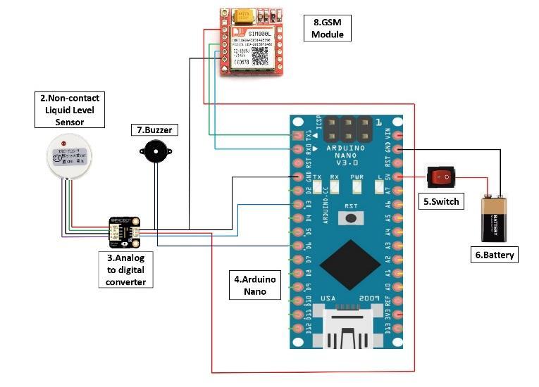
Figure 1 Thecircuitconnectionsofthepresentinventionareshown inFigure2.
LOW && MakeCallCount == 0&&SendMessageCount==0)//Checkthesensoroutput{ if(digitalRead(FluidSensor)==SendMessage();MakeCall();Serial.println("HELP//Fluid_low_Count++;ME");}
International Research Journal of Engineering and Technology (IRJET) e ISSN: 2395 0056 Volume: 09 Issue: 03 | Mar 2022 www.irjet.net p ISSN: 2395 0072
© 2022, IRJET | Impact Factor value: 7.529 | ISO 9001:2008 Certified Journal | Page55
Serial.write(mySerial.read());ifdelay(10);(mySerial.available()>0){}} void mySerial.println("ATD+xxxxxxxxxxxx;");MakeCallCount++;MakeCall(){ // ATDxxxxxxxxxx; watch out here for semicolon at the delay(10000);end!!} void mySerial.println("AT+CMGF=1");SendMessage(){
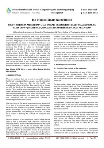
3. Description of Drawings: The block diagram of the present invention is shown in Figure1. The innovation can be divided into two subsystems: one that includes all of the sensors, and another that includes themicrocontroller. A saline bottle 1, a non contact liquid level sensor 2, a switch5,abattery6,abuzzer7,andareceiver9makeup thesensorysubsystem. InventionalsoincludesanArduinoNano4, anADC3, and aGSMmodule8,allofwhichareconnectedtotheArduino Nano.
ifvoiddelay(100);Serial.begin(9600);}loop(){(digitalRead(FluidSensor)==LOW){ digitalWrite(buzzer,HIGH);} digitalWrite(buzzer,else{LOW);} if(digitalRead(FluidSensor)==
[4] D.Baviskar, P.Patil, S.Bhatambre, M.Hake, and S.Adsure, IoT BASED SALINE LEVEL MONITORING SYSTEM, Open access international journal of science,10.1088/1757 899X/981/3/032095
© 2022, IRJET | Impact Factor value: 7.529 | ISO 9001:2008 Certified Journal | Page56
[3] S.Gupta, M.Kulkarni, and Y.Kulkarni, Smart Saline Monitoring System Using Load Cell and RF Sensor, International Research Journal of Engineering and Technology(IRJET),05(06)|,2018.
Volume: 09 Issue: 03 | Mar 2022 www.irjet.net p ISSN: 2395 0072
REFERENCES
International Research Journal of Engineering and Technology (IRJET) e ISSN: 2395 0056
4. CONCLUSION Medical workerswill benefitgreatlyfromthistechnology, which will aid in the prevention of medical errors in hospitals. It's a low cost product with a high quality component,thusit'scost effectiveintermsofmoney.This reduces nonproductive work and prevents medical mishapsthatcanoccurifasalineorelectrolytebottleisn't refilledorreplenishedontime.
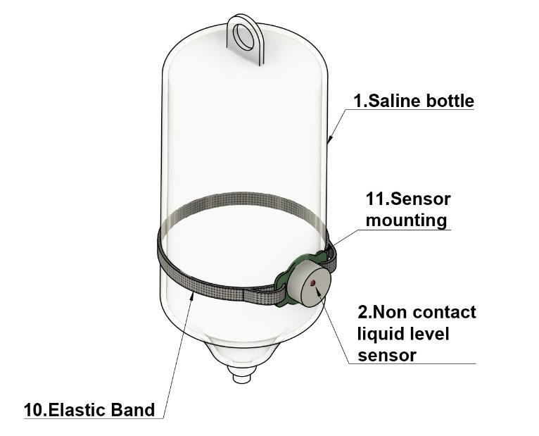
Pin30oftheArduinoNANO4isconnectedtothepositive terminal of a 9V rechargeable battery 6 via switch 5 with red wire, and pin 29 of the Arduino NANO 4 is connected tothe negativeterminal ofthebatteryvia black wire. The GSM module 800L 8, VCC pin 2, and A to D converter 3, VCC pin 2 are likewise linked to the Arduino NANO 4, pin 30 with red wire. GSM module 800L 8, pin 6, analogue to digital converter 3, digital pin 3 and buzzer 7, negative terminalwithblackwirearealllinkedtopin29ofArduino NANO4. GreenwireconnectstheArduinoNANO4,pin1,TX1tothe GSM module 800L 8, pin 4, RXD. Pin 2 of the Arduino NANO 4 is connected to the GSM module 800L 8, pin 5 of the TXD with blue wire, and pin 2 of the Arduino NANO 4 is connected to the GSM module 800L 8, pin 5 of the TXD withbluewire. With purple wire, Arduino NANO 4, pin 9, D6 is linked to the buzzer 7, positive terminal. The analogue to digital 15 converters digital 3, pin 1, OUT is linked to the Arduino NANO4,pin6,D3usingbluewire. Thenon contactliquidlevelsensor2,pin1(Brown),VCCis linkedto theanalogueto digital converter3, analogue pin 1,VCC via red wire. The non contactliquidlevel sensor 2, pin2(Yellow),islinkedtotheanaloguetodigitalconverter 3, analogue pin 2, OUT using green wire. The non contact liquid level sensor 3, pin 3(Blue), GND with black wire is linked to analogue pin 3 of the analogue to digital converter 3.The analogue todigital converter 3,analogue pin4,ADJislinkedtothenon contactliquidlevelsensor2, pin4(black),ADJwithpurplewire. Figure 2 Theisometricexemplarydiagramofthepresentinvention isshowninFigure3. The typical diagram of the sensor retrofitted to the bottle demonstrates how it will be done clearly. A resizable elastic band 10 will be used to bind the sensor 2 to its mount 11and tothesaline bottle1.Thesensor2 will not be overly tight or loose around the saline bottle 1 if this fitting is used. The mount 11 is comprised of a flexible plasticmaterial.Thisarrangementisintendedtobesimple andreliable. Figure 3
[1] Introduction to Lithium Polymer Battery Technology Introduction to Lithium Polymer Battery Technology 2.(n.d.).www.jauch.com, [2] Arduino, “Arduino Reference,” Lang. Ref., p. 1, Reference/HomePage.2016,[Online].Available:https://www.arduino.cc/en/
International Research Journal of Engineering and Technology (IRJET) e ISSN: 2395 0056 Volume: 09 Issue: 03 | Mar 2022 www.irjet.net p ISSN: 2395 0072 © 2022, IRJET | Impact Factor value: 7.529 | ISO 9001:2008 Certified Journal | Page57 [5] A.Phaniraj, Gayatri K, J.Thomas, and Dr S Prabhanja, Management of Saline and Electricity using IOT, Journal of Computer Science Engineering and SoftwareTesting,4(3),2018
Miss. VISHAKHA A. KOSHTI, is in Final year of Department of Biomedical Engineering, U.V. Patel College of Engineering,GanpatUniversity. Miss. BANSARI J. SHAH, isinFinalyearof Department of Biomedical Engineering, U.V. Patel College of Engineering, Ganpat University.


Mr. FALGUN P. BHATT, isinFinal year of Department of Biomedical Engineering, U.V. Patel College of Engineering, Ganpat University.
Mr. NISARG M. RAVAL, is in Final year of Department of Biomedical Engineering, U.V. Patel College of Engineering, Ganpat University.


Mr. DHRUV J. PATEL, is in Final year of Department of Biomedical Engineering, U.V. Patel College of Engineering, Ganpat University.

BIOGRAPHIES

Mr. NEEL V. SHAH, is in Final year of Department of Biomedical Engineering, U.V. Patel College of Engineering, Ganpat University.
