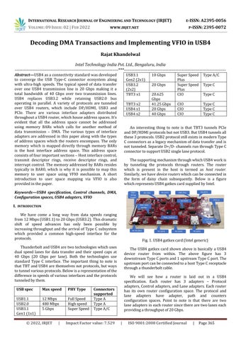
ThesupportingmechanismthroughwhichUSB4workis by tunneling the protocols through routers. The router which is present in the host is termed as host router. Similarly,wehave device routers whichcanbeconnectedin the form of daisy chain subsequently. Below is a figure whichrepresentsUSB4gatkexcardsuppliedbyIntel.
We have come a long way from data speeds ranging from12Mbps(USB1.1)to20Gbps(USB3.2).Thisdramatic shift of speed advances has only been possible by increasingthroughputandthearrivalofTypeCsubsystem which provided a common high speed interface for the protocols.ThunderboltandUSB4aretwotechnologieswhichuses dual speed lanes for data transfer and their speed caps at 40 Gbps (20 Gbps per lane). Both the technologies use standard Type C interface. The important thing to note is thatTBTandUSB4arethemselvesnotprotocols,butways totunnelvariousprotocols.Belowisarepresentationofthe differenceinspeedsofvariousinterfacesandtheprotocols tunneledbythem. USB spec Max speed PHY Type sConnectorsupported USB1.1 12Mbps FullSpeed TypeA USB2.0 480Mbps Highspeed TypeA Gen1USB3.1(1x1) 5Gbps SuperSpeed TypeA/C
I. INTRODUCTION
Fig.1.USB4gatkexcard(Intelgeneric)
The USB4 gatkex card shown above is basically a USB4 device router from within. The above figure has 3 downstreamTypeCportsand1upstreamTypeCport.The upstreamportcanbeconnectedtoahostTypeCreceptacle throughathunderboltcable.
An interesting thing to note is that TBT3 tunnels PCIe andDP/HDMIprotocolsbutnotUSB3.ButUSB4tunnelsall these3protocols.USB2protocolstillexistsinmodernType Cconnectorsasalegacymechanismofdatatransferandis nottunneled.SeparateD+/D channelsrunthroughTypeC connectortosupportUSB2singlelaneprotocol.
We will see how a router is laid out in a USB4 specification. Each router has 3 adapters Protocol adapters,Controladapters,andLaneadapters.Eachrouter has its own router configuration space. The protocol and lane adapters have adapter, path and counters configuration spaces. Point to note is that there are two laneadaptersineachroutersincetherearetwolaneseach providingathroughputof20Gbps.
Gen2USB3.1(2x1) 10Gbps SuperSpeed Plus TypeA/C (2x2)USB3.2 20Gbps SuperSpeed Plus TypeC TBT3x1 Gbps20.625 CIO TypeC TBT3x2 41.25Gbps CIO TypeC USB4x1 20Gbps CIO TypeC USB4x2 40Gbps CIO TypeC
INTERNATIONAL RESEARCH JOURNAL OF ENGINEERING AND TECHNOLOGY (IRJET) E ISSN: A2395 0056 VOLUME: 09 ISSUE: 02 | FEB 2022 WWW.IRJET.NET P ISSN: 2395 0072 © 2022, IRJET | Impact Factor value: 7.529 | ISO 9001:2008 Certified Journal | Page365
Decoding DMA Transactions and Implementing VFIO in USB4 Rajat Khandelwal Intel Technology India Pvt. Ltd., Bengaluru, India ***
Abstract USB4asaconnectivitystandardwasdeveloped to converge the USB Type C connector ecosystem along with ultra high speeds. The typical speed of data transfer over one USB4 transmission line is 20 Gbps making it a total bandwidth of 40 Gbps over two transmission lines. USB4 replaces USB3.2 while retaining USB2.0 bus operating in parallel. A variety of protocols are tunneled over USB4 routers, which include DP/HDMI, USB3 and PCIe. There are various interface adapters distributed throughoutaUSB4router,whichhouseaddressspaces.It’s evident that all the address space cannot be addressed using memory BARs which calls for another method of data transmission DMA. The various types of interface adapters are addressed in this paper along with the types of address spaces which the routers encompass. The only memory which is mapped directly through memory BARs is the host interface address space. This address space consistsoffourimportantsections Hostinterfacecontrol, transmit descriptor rings, receive descriptor rings, and interruptcontrol. ThememoryaddressedbyBARsresides typically in BAR0, which is why it is possible to map this memory to user space using VFIO mechanism. A short introduction to user space mapping via VFIO is also providedinthepaper.
Keywords USB4 specification, Control channels, DMA, Configuration spaces, USB4 adapters, VFIO

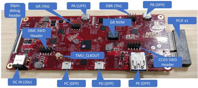
This router contains two downstream USB4 Type C portsandoneupstreamport.Aswecansee,therearePCIe upstreamandPCIedownstreamadapterscorrespondingto the direction of the data flow. Similarly, we have USB3 upstream and downstream adapters. There is also a time management unit (TMU) which supports time synchronizationwithinrouters. As representedinthefigure,USB2lanesrunseparately throughachannelwhichiscalledD+/D channelinTypeC receptacle.
IV.TRANSPORT LAYER
INTERNATIONAL RESEARCH JOURNAL OF ENGINEERING AND TECHNOLOGY (IRJET) E ISSN: A2395 0056
A. Control packets: A read/write control packet can be transmitted from host to a router and from a router to a host. When the flow direction is from hosttorouter,thepacketistransmittedfromhost to host interface adapter, then it goes to control adapter,thentothetransportlayerandthentothe respective configuration space. Similarly a control packet received from a router’s configuration space is transmitted from configuration space to transportlayertocontroladaptertohostinterface layertolaneadaptertofinallyhost.
III.ADAPTERS AND CONFIG SPACES
VOLUME: 09 ISSUE: 02 | FEB 2022 WWW.IRJET.NET P ISSN: 2395 0072 © 2022, IRJET | Impact Factor value: 7.529 | ISO 9001:2008 Certified Journal | Page366
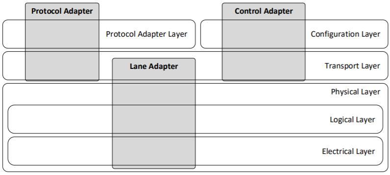
All the adapters except control adapters house configuration spaces Adapter config space, Path config space and Counter config space. In addition, each router also has its own router config space and a sideband (SB) register space which is addressed throughSBUtransactions. As explained earlier, the registers residing in host interface layer can be easily addressed using memory BAR0. And thus, they can be easily ported to user space usingVFIO.Theconfigurationspacescanonlybeaddressed usingTheDMA.figure given below represents various layers and adaptersinaUSB4router.
Fig.3.USB4adaptersacrossfunctionallayers
Theprotocoladaptersaresubdividedintoupstreamand downstream protocol adapters whichare specific to USB3, PCIe and DP/HDMI. They are basically used to convert USB4trafficintoprotocoltrafficandviceversa.
B. USB3 packets: For the USB3 packets going from USB3hosttorouter,thetransmissionflowisUSB3 host to USB3 interface adapter to control adapter totransportlayertorespectiveadapter.
C. PCIe packets: PCIe packets are transmitted from a PCIe end point to a PCIe bridge (if exists) to PCIe interface adapter to control adapter to transport layertorespectiveadapter.
Thereexistsahostinterfaceadapterwhichispresentin the host interface layer. This layer houses N transmit descriptor rings and N receive descriptor rings. The transmit ring and receive ring with hop ID 0 is used to communicate between host (connection manager) and the USB4Thisdomain.hostinterfacelayerhousescertainregisterswhich are mapped via memory PCIe BARs. The configuration spaces however are large and thus can only be addressed through DMA. This paper primarily focuses on how the DMA transactions take place and what they are made of. Further we will see how can we map the host interface layertouserspaceviaVFIO.
There are three types of adapters in a USB4 router Protocoladapters,ControladaptersandLaneadapters.We have two types of protocol adapters Host interface adapter and generic protocol adapters (USB3/DP/HDMI/PCIe).
A USB4 router can be theoretically represented in the formgivenFig.below.2.RepresentationofaUSB4router
Allthepacketsonarrivingarouteraredirectedtoward transport layer. Following is the direction flow of all the packetsthatarepresentasapartofUSB4transaction.
II. LAYOUT OF A ROUTER
D. DP/HDMI packets: DP/HDMI packets are direct flow packets. They have a source and destination. They originate from a DP/HDMI source and are transmitted to DP/HDMI interface adapter to control adapter to transport layer to respective adapter.

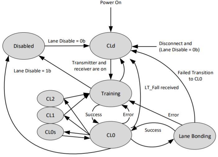
B. CLd state: Lane adapter transmitter and receiver areinactive.
VI.LANE ADAPTER STATE MACHINE
G. Broadcast retimer type transactions: BRT transactions are also SB transactions which are transmittedtoenumerateretimers.Therecanbea maximumof6retimersbetweentworouters.Thus retimernumberingcangofrom1tomaximumof6. BRT transactions occur in both directions from routerAtorouterBandviceversa.Theyhavethe samepathasthatofLTtransactions.
E. Lane bonding state: bonds two single lane links intoaduallanelink.
D. CL0 state: The lane adapter can transmit and receivetransportlayerpacketsacrossthelane.
adapterUpstream
F. Administrative type transactions: AT transactions are used at the time of router enumeration and they serve the purpose of identifying lanes, generation and speed in a router. They have the samerouteasthatoflink typetransactions.These arealsoSBtransactionsandaretransmittedalong theSBUlines.
F. CL0s,CL1andCL2state:Lowpowerstates.[3]
H. Addressed retimer transactions: ART transactions aresolelyusedforTxFFEnegotiations.Thereexists a TxFFE register in SB register space of each router. ART transactions follow the same route as thatofLTtransactions.
Maxadapter
pointercapabilityNext
V. TIME SYNCHRONIZATION
C. Training state: The lane adapter performs symbol synchronizationandtransferoflaneparameters.
The following configuration registers are present in routerconfigspace. Register name Bit(s) Field name ROUTER_CS_0 15:0 VendorID 31:16 DeviceID ROUTER_CS_1 7:0 13:8 19:14 22:20 ROUTER_CS_2 23 Rsvd
VII. ROUTER CONFIGURATION SPACE
E. Link type transactions: These originate from logicallayerandareusedduringlaneinitialization. They are also used to signal a change in adapter state due to events such as a lane disconnect or transitiontoalowpowerstate.LTtransactionsare transmittedfromlogicallayertocontroladapterto transport layer to SB (sideband) channel to SB channel of another router to control adapter to transportlayertorespectiveSBregisterspace.
The state machine in the given figure describes the behavior of the logical layer in a lane adapter. A detailed description of the states and transitions between states follows.A.
The Time Synchronization Protocol is a distributed protocol that defines how the real time clocks in a USB4 fabricsynchronizewitheachother.Thereal timeclocksare organizedintoahierarchywiththehostrouteratthetopof thehierarchydeterminingthereferencetimefortheentire domain. Clock synchronization is achieved by exchanging ordered sets and time sync packets where downstream devices use both local timestamps and the timing information in the time sync Packets to adjust their clocks tothetimeofthehostrouter.
INTERNATIONAL RESEARCH JOURNAL OF ENGINEERING AND TECHNOLOGY (IRJET) E ISSN: A2395 0056 VOLUME: 09 ISSUE: 02 | FEB 2022 WWW.IRJET.NET P ISSN: 2395 0072 © 2022, IRJET | Impact Factor value: 7.529 | ISO 9001:2008 Certified Journal | Page367
Disabledstate:Thelaneadapterdisablesthelane.
Depth
When Inter Domain time synchronization is disabled, the time synchronization protocol executes within the scope of a single domain. All time sync packets, state machines and other entities are associated with a single domain. The time established within one domain by the protocolisindependentofthetimeinotherdomains.
When Inter Domain time synchronization is enabled, the time synchronization protocol executes within the scopeofaninterconnectedsetof domains.TheConnection Manager s of the domain establish an Inter Domain clock synchronization hierarchy by selecting one of the host routers to be the time source for all domains. The time synchronization protocol then synchronizes the clocks of the other domains to the Inter Domain host router clock. [3]
ROUTER_CS_3 31:0 Topology ID low ROUTER_CS_4 23:0 Topology ID high 30:24 Rsvd 31 Topology ID valid ROUTER_CS_5 7:0 timeoutNotification 15:8 CM USB4 version 23:16 Rsvd 31:24 USB4version ROUTER_CS_6 0 Entersleep 1 Enable wake onPCIe 2 WOUSB3 3 Enable wake onDP 22:4 Rsvd 23 CM supportTBT3 24 tunnelingPCIeON 25 tunnelingUSB3ON 26 Internal host controllerON 30:27 Rsvd 31 validConfiguration ROUTER_CS_7 0 Sleepready 1 TBT3 supportednot 2 Wake on PCIestatus 3 Wake on USB3status 4 Wake on DP status 17:5 Rsvd 18 Internal implementedcontrollerhost 23:19 Rsvd 24 Routerready 25 Configready 31:26 Rsvd
ROUTER_CS_8 31:0 UUIDhigh ROUTER_CS_9 31:0 UUIDlow ROUTER_CS_10 31:0 Data[0] ROUTER_CS_11 31:0 Data[1] ROUTER_CS_12 31:0 Data[2] ROUTER_CS_13 31:0 Data[3] ROUTER_CS_14 31:0 Data[4] ROUTER_CS_15 31:0 Data[5] ROUTER_CS_16 31:0 Data[6] ROUTER_CS_17 31:0 Data[7] ROUTER_CS_18 31:0 Data[8] ROUTER_CS_19 31:0 Data[9] ROUTER_CS_20 31:0 Data[10] ROUTER_CS_21 31:0 Data[11] ROUTER_CS_22 31:0 Data[12] ROUTER_CS_23 31:0 Data[13]
The host interface layer of a USB4 router houses these registers: Offset Register name Host interface control 39640h Hostinterfacecapabilities 39858h Hostinterfacereset 39864h Hostinterfacecontrol 39880h HostinterfaceCL1enable 39884h HostinterfaceCL2enable Transmit descriptor rings 00000h+n*10h Baseaddresslow 00004h+n*10h Baseaddresshigh 00008h+n*10h Producer and consumer
INTERNATIONAL RESEARCH JOURNAL OF ENGINEERING AND TECHNOLOGY (IRJET) E ISSN: A2395 0056 VOLUME: 09 ISSUE: 02 | FEB 2022 WWW.IRJET.NET P ISSN: 2395 0072 © 2022, IRJET | Impact Factor value: 7.529 | ISO 9001:2008 Certified Journal | Page368 31:24 numberRevision
ROUTER_CS_24 31:0 Data[14] ROUTER_CS_25 31:0 Data[15] ROUTER_CS_26 31:0 Metadata ROUTER_CS_27 15:0 Opcode 23:16 Rsvd 29:24 Status 30 supportednotOperation 31 validOperation
VIII.ADAPTER CONFIGURATION SPACE
The above table is provided to give a representation of whatarouterconfigspacelookslike.
Every adapter (except for a control adapter) shall have its own adapter configuration space. The adapter configuration space structure begins with a set of doublewords describing the basic attributes of an adapter. The rest of the space is populated with a linked list of capabilities.AConnection Manager reads from or writes to adapter configuration space using the read requests and write requests defined. A router shall allow a Connection Manager to access adapter configuration space regardless ofwhetherornottheadapterisconnected.[3]
IX.USB4 HOST MEMORY
X. CONTROL RINGS AND DMA MAPPING
ThebuffertobetransmittedisappendedwithaCRCto detect inconsistency in data transmitted. The buffer is allocated a DMA address via coherent kernel methods and the address is stored in ‘Address low’ and ‘Address high’ fields in the transmit descriptor present at producer index ofthetransmitringwithhopID0.
XI.TRANSMIT INTERFACE
Data length No of bytes to be transmitted from thisdatabuffer
Interrupt enable If set to 1, host interface layer issuesaninterrupttotheconnectionmanagerafter updating‘Descriptordone’field
DW Bits Name 0 0 31 Addresslow 1 0 31 Addresshigh 2 0 11 Datalength 12 15 EOFPDF 16 19 SOFPDF 20 Rsvd 21 Descriptordone 22 Requestdone 23 Interruptenable 3 0 31 Rsvd Addresslow lower32bitsofDMAaddressofthe buffertobetransmitted Address high higher 32 bits of DMA address of thebuffertobetransmitted
INTERNATIONAL RESEARCH JOURNAL OF ENGINEERING AND TECHNOLOGY (IRJET) E ISSN: A2395 0056 VOLUME: 09 ISSUE: 02 | FEB 2022 WWW.IRJET.NET P ISSN: 2395 0072 © 2022, IRJET | Impact Factor value: 7.529 | ISO 9001:2008 Certified Journal | Page369 indexes 0000Ch+n*10h Ringsize 19800h+n*20h Ringcontrol Receive descriptor rings 08000h+n*10h Baseaddresslow 08004h+n*10h Baseaddresshigh 08008h+n*10h Producer and consumer indexes 0800Ch+n*10h Ringandbuffersize 29800h+n*20h Ringcontrol 29804h+n*20h PDFbitmasks Interrupts 37800h : 37800h + (4 * ceiling(3N/32) 1) Interruptstatus(ISR) 37808h : 37808h + (4 * ceiling(3N/32) 1) Interruptstatusclear(ISC) 37810h : 37810h + (4 * ceiling(3N/32) 1) Interruptstatusset(ISS) 38200h : 38200h + (4 * ceiling(3N/32) 1) Interruptmask(IMR) 38208h : 38208h + (4 * ceiling(3N/32) 1) Interruptmaskclear(IMC) 38210h : 38210h + (4 * ceiling(3N/32) 1)I Interruptmaskset(IMS) 38C00h:38C3Ch Interrupt throttling rate (ITR) 38C40h : 38C40h + (4 * ceiling(3N/8) 1) Interrupt vector allocation (IVAR) 18C00h :18C00h + (4 * ceiling(N/8) 1) Receive ring vacancy control 19400h :19400h + (4 * ceiling(N/32) 1) Receiveringvacancystatus HerenrepresentsthehopIDofthering.
The table below depicts the contents of a transmit descriptor.
Descriptor done Set to 0 when posting a data buffertobetransmitted.If‘RequestStatus’fieldis setto1,hostinterfacelayersetsthisfieldto1after the last byte is sent to transport layer. If ‘Request Status’fieldissetto0,hostinterfacelayerdoesn’t writetothisfield
Consumer index of transmit ring Index of the next transmitdescriptortobeprocessedbyhostinterfacelayer.
Request Status Determines the update policy of ‘Descriptordone’field
The transmission of descriptor to host interface layer starts when producer index ≠ consumer index. Initially, both are set to 0 by the connection manager. So, when transmission is to start, producer index is increased by 1. Now, the transmit descriptor at producer index is
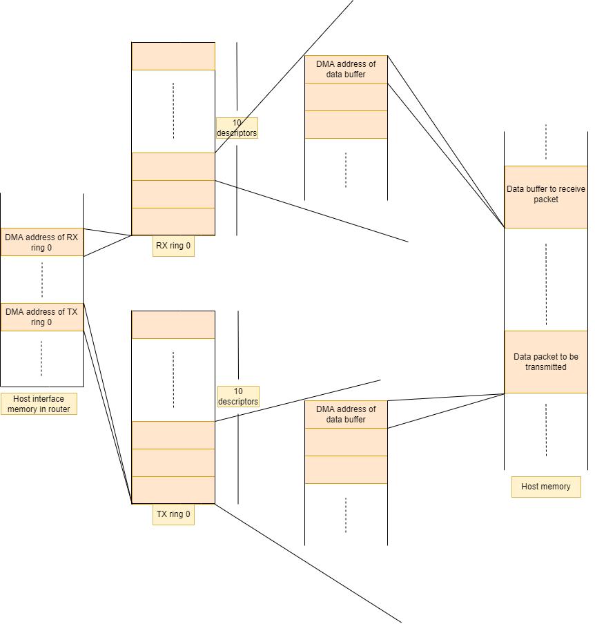
A finite number of transmit descriptor and receive descriptor rings are allocated by the connection manager. In Linux, the number is 10, i.e., the number of hop IDs allocatedis10.TheringwithhopID0iscalledcontrolring since it is used extensively by the connection manager to read/writeconfigurationspaces(controlpackets).
ADMAaddressisallocatedviacoherentkernelmethods foreachtransmit/receivering.TherespectiveDMAaddress of a ring is then written into ‘base address low’ and ‘base address high’ fields in the host memory (Refer sec. IV) corresponding to the respective ring. ‘Ring size’ field also getswritten(inLinux,witha valueof10),i.e.,atotal of10 descriptors per ring. The producer and consumer index fieldsgetwrittento0foreachringinitially.
EOFPDF PDFvalueofthetransportlayerpacket containingthisbuffer;PDF protocoldefinedfield SOFPDF Ignore
Producer index of transmit ring Index of the next transmitdescriptorthehostwritesto.
INTERNATIONAL RESEARCH JOURNAL OF ENGINEERING T (IRJET) E ISSN: A2395 0056
Producer index of receive ring Index of the next receivedescriptorthatthehostinterfacelayerwritesto.
The host interface layer increases producer index by 1 and fetches the transport layer packet from the transport layer and posts the content at the DMA address presentin ‘addresslow’and‘addresshigh’fieldsofthedescriptor.The host interface layer is also responsible to remove the transport layer header from the packet received from the transportlayer.
ECHNOLOGY
EOFPDF PDFvalueofthetransportlayerpacket carryingdatafromatransmitdescriptor
Request Status Determines the update policy of ‘Descriptordone’field Interrupt enable If set to 1, host interface layer issuesaninterrupttotheconnectionmanagerafter updating‘Descriptordone’field Offset offset of the host memory data buffer at whichthedataistobereceived
Address high higher 32 bits of DMA address of the data buffer to receive contents from the domain Datalength Noofbytestobereceivedinthedata buffer
VOLUME: 09 ISSUE: 02 | FEB 2022 WWW.IRJET.NET P ISSN: 2395 0072 © 2022, IRJET | Impact Factor value: 7.529 | ISO 9001:2008 Certified Journal | Page370 transmittedtothehostinterfacelayer.TheDMAaddressof this transmit descriptor is calculated by increasing the address contained in ‘base address low’ and ‘base address high’ fields of host interface memory transmit ring by the producerindex.
DW Bits Name 0 0 31 Addresslow 1 0 31 Addresshigh 2 0 11 Datalength 12 15 EOFPDF 16 19 SOFPDF 20 CRCerror 21 Descriptordone 22 Bufferoverflow 23 Interruptenable 24 31 Offset 3 0 31 Rsvd
The host interface layer sets the ‘Buffer overflow’ bit if thesizeofthepayloadexceedstheavailablesizeinthedata bufferinthehostmemory.
Consumer index of receive ring Index of the next receive descriptor that the host provides to the host interfacelayer.
The transmission of buffer from transportlayer tohost memory starts when producer index ≠ consumer index. Initially, both are set to 0 by the connection manager. So, whentransmissionistostart, consumerindexisincreased by1.Now,thereceivedescriptoratconsumerindexisfilled bythehostinterfacelayer.TheDMAaddressofthisreceive descriptoriscalculatedbyincreasingtheaddresscontained in ‘base address low’ and ‘base address high’ fields of host interfacememoryreceiveringbytheconsumerindex.
AND
The host interface layer processes the transmit descriptorandfetchesthebufferatDMAaddresspresentin ‘addresslow’and‘addresshigh’fieldsofthedescriptor.The host interface layer is also responsible to prepend the transport layer packet header into the buffer fetched from hostmemory.Nowthistransportlayerpacketisappended a PDF packet equal to EOF PDF field of the transmit descriptor.Whenthe last byte of the transport packet formed is transmitted to transport layer, the host interface layer increases the consumer index by 1 and updates the ‘Descriptor done’ field depending on ‘Request done’ field and issues an interrupt according to the ‘Interrupt enable’ fieldsetbytheconnectionmanager.
The data buffer in the host memory is allocated a DMA address via coherent kernel methods and the address is stored in ‘Address low’ and ‘Address high’ fields in the receivedescriptorpresentatconsumerindexofthereceive ringwithhopID0.
When the last byte of the transport packet formed is transmitted to host memory, the host interface layer updates the ‘Descriptor done’ field depending on ‘Request done’ field and issues an interrupt according to the ‘Interruptenable’fieldsetbytheconnectionmanager.
SOFPDF Setto0 CRC error indicates if there is an error in the frameCRC Descriptor done Set to 0 initially. If ‘Request Status’fieldissetto1,hostinterfacelayersetsthis fieldto1afterthelastbyteissenttohostmemory. If ‘Request Status’ field is set to 0, host interface layerdoesn’twritetothisfield
The host on receiving an interrupt comes to know that thebufferissuccessfullytransmittedtothetransportlayer.
The table below depicts the contents of a receive descriptor.
XII. RECEIVE INTERFACE
Addresslow lower32bitsofDMAaddressofthe databuffertoreceivecontentsfromthedomain
Once the group is prepared, it is attached to the container using VFIO_GROUP_SET_CONTAINER ioctl call, passingthefiledescriptorthecontainerfileopened.
E. Create a container by opening the character file /dev/vfio/vfio.
A crucial point to note is that for DMA transactions to happen on any PCIe endpoint device, bus mastering needs to be enabled. Thus, a value of PCI_COMMAND_MASTER (0x4)isstoredinthePCI_COMMANDregisterinPCIeconfig spacebytheconnectionmanager. XIII.VFIO
Here,wegiveapreparedcodetomapthehostinterface memoryofhostUSB4routerandreadthenumberofpaths. The number of paths is present in bits [10:0] of Host interface capabilities register in host interface layer. The stepstodosobyVFIOarelistedbelow:
The host on receiving an interrupt comes to know that thebufferissuccessfullyreceivedinthehostmemory. Thus, it can be proved that the transmit/receive flow requires two separate DMA transactions, which is illustratedinthefigurebelow. Fig.4.PictorialrepresentationofDMAflowsintransmit andreceivedescriptors
D. Check if there are other devices present in the iommu group the USB4 device is in. If so, unbind their respective drivers and bind the vfio pci driver.
I. Get the BAR0 region information using VFIO_DEVICE_GET_REGION_INFOioctlcall.
All the ioctl calls which are associated with VFIO are presentinthelinux/vfio.hfile.
C. Bindthevfio pcidrivertothedevice.
The VFIO driver framework provides unified APIs for direct device access. It is an IOMMU/device agnostic framework for exposing direct device access to user space in a secure, IOMMU protected environment. This framework is used for multiple devices, such as GPUs, network adapters, and compute accelerators. With direct device access, virtual machines or user space applications havedirectaccesstothephysicaldevice.[4] Devices are the main target of any I/O driver. Devices typically create a programming interface made up of I/O access,interrupts,andDMA.Withoutgoingintothedetails of each of these, DMA is by far the most critical aspect for maintaining a secure environment as allowing a device read write access to system memory imposes the greatest risktotheoverallsystemintegrity
B. Unbind the native thunderbolt driver from the USB4PCIedevice.
INTERNATIONAL RESEARCH JOURNAL OF ENGINEERING AND TECHNOLOGY (IRJET) E ISSN: A2395 0056 VOLUME: 09 ISSUE: 02 | FEB 2022 WWW.IRJET.NET P ISSN: 2395 0072 © 2022, IRJET | Impact Factor value: 7.529 | ISO 9001:2008 Certified Journal | Page371
On its own, the container provides very little functionality. The user has to add groups in the container for the next level of abstraction. This is done easily by unbinding the native driver to the device and binding it to vfio pci driver. By doing so, a VFIO group will appear in sysfsas Here,/dev/vfio/<GROUP>.GROUPistheIOMMUgroupnumberofwhichthe deviceisamember.Ifmorethanonedeviceisamemberof the group, all the devices should be added in the group by unbindingandbinding.
VFIO makes use of containers which hold one/more groups. A container is created by simply opening the characterdeviceexposesbyVFIOinsysfs /dev/vfio/vfio
A. Enable the vfio pci driver by setting the kernel config:CONFIG_VFIO_PCI=y.
F. Open the group created in sysfs under /dev/vfio/<GROUP>.
J. The above region information contains size and offset.So,nowmaptheregionusingmmapsystem callwiththegivensizeandoffset.
G. Bind the group to the container created by using VFIO_GROUP_SET_CONTAINERioctlcall. H. Enable type 1 IOMMU by using VFIO_SET_IOMMU ioctlcall.
[1] TailorNeelKishorkumar,“USB3.0protocol” [2] POINTGREY Innovation in Imaging, “USB 3.0: Improvements overUSB2.0”,February,2013 [3] Apple Inc, HP Inc, Intel Corporation, Microsoft Corporation,RenesasCorporation,STMicroelectronics, Texas Instruments, “Universal Serial Bus 4 (USB4) Specification”,revision1.0,October,2020 [4] Neo Jia, Kirti Wankhede, “VFIO Mediated Devices”, 2016 [5] Alex Williamson, “VFIO: A User’s Perspective”, November,2012 [6] Intel Corporation, “Intel USB4 Evaluation Dock EVB UserManual”,revision4.0,May,2021 [7] Sony, “What are the USB4 data transfer rates and specifications?”,March,2022
I wouldlike toacknowledgeIntel for providing me this opportunity to share my research work on USB4. I would also like to thank Rajaram Regupathy who helped me in mappinghostinterfacememorythroughVFIO.
ACKNOWLEDGMENT
INTERNATIONAL RESEARCH JOURNAL OF ENGINEERING AND TECHNOLOGY (IRJET) E ISSN: A2395 0056 VOLUME: 09 ISSUE: 02 | FEB 2022 WWW.IRJET.NET P ISSN: 2395 0072 © 2022, IRJET | Impact Factor value: 7.529 | ISO 9001:2008 Certified Journal | Page372 K. That’s it. Now the BAR0 has been completely mapped and now you can access any register by dereferencingpointeraddress. The complete code to map the host interface layer registers and print the number of paths is given in the belowhttps://github.com/rajatkha/libusb4link:
REFERENCES