Abstract: Interplanetary missions have always been a field of interest for humans. Wehave always wanted to explore why life exists the way it does on our planet and not on other neighboring planets. We ponder upon questions like: “Didthe other planets have life earlier?” or “Will we able to thrive on other planets?” To try to answer these questions, wemustbeabletostudytheplanet’sconditions.
1. Introduction
Withthismission,certainmysteriesofoursisterplanetwillbeunveiledjust likethepreviousVeneramissions, VegamissionsandVenusExpressmission.Themainobjectiveofthisprojectistodesignapropulsionsystemforan inter planetary mission to Venus which carries a CubeSat for studying the unknownUV absorbers present in the Venusian atmosphere. This is done to determinethe nature, concentration and distribution of UV absorbers andtounderstandtheoverallradiativeandthermalbalanceoftheplanetalongwiththeatmospheric dynamics and thechemistryoftheupperclouds.
© 2022, IRJET | Impact Factor value: 7.529 | ISO 9001:2008 Certified Journal | Page324
RecentstudyhasshownthatanunknownabsorberisVenus’cloudsabsorbsin theUV 50percentoftheincoming solarradiation. TheabsorbedenergyistheprimaryatmosphericengineofVenus. Thismissionpayloadwillbea
4Department of Electronics and Instrumentation, Ramaiah Institute of Technology, Bangalore 560 054, Karnataka, India***
3Department of Chemistry, Ramaiah Institute of Technology, Bangalore 560 054, Karnataka, India
The endeavor to launch a spacecraft to Venus is to increase the understanding on our sister planet, Venus. Venus’s mysterieshaveamusedusallincludingtherecentdiscoveryofphosphinegasintheplanet’supperatmospherethat couldturnscientists’gazetoaplanetlongoverlookedinthesearchforextraterrestriallife.
1. CubeSat UV Experiment
Currently,therehasbeenagreatdemandforspacemissionsandalsoaneedtomake these missions affordable, efficient and safe. Venus, our sister planet, hasmany mysteries that need to be unveiled. By understanding the conditions of planets like Venus, we could figure out what makes Earth a haven for human life.In this paper, we have designed a propulsion system, for a spacecraft, thatwouldtakea payloadfromEarth’s orbit(400kmfromsurface) toa desiredorbit aroundVenus,tounveilthesemysteries.
Keywords:propellant,chemicalrocketpropulsion,CubeSat,numericalanalysis,simulations,specificimpulseetc.
Analysis and Design of a Propulsion System for an Interplanetary Mission to Venus Jagannath Prasad Sahoo1*, Deepayan Narayan choudhary2, Manjappa Praveen3, Siddhi Samrata4
Today, the second planet from the sun has an atmosphere stifled by carbon dioxide gas, and surface temperatures that average more than 800 degrees Fahrenheit. The dense atmosphere of Venus exerts a pressure of more than 1,300 pounds per square inch on anything at the surface. That is more than 90 times the 14.7 pounds per square inch at sea level on Earth, or the equivalent to being 3,000 feet underwater in the ocean. High in the toxic atmosphereoftheplanet Venus,astronomers on Earth have discovered signs of what might belife.Oftencalled Earth’stwin,Venus isroughlythesamemassasEarth. Many scientists think thatVenus wasoncecoveredinwater andpossessedanatmospherewherelifeasweknowitcouldhaveflourished.
2. Methodology a. | PayloadSelection
1*,2Department of Mechanical, Ramaiah Institute of Technology, Bangalore 560 054, Karnataka, India
International Research Journal of Engineering and Technology (IRJET) e ISSN: 2395 0056 Volume: 09 Issue: 02 | Feb 2022 www.irjet.net p ISSN: 2395 0072

International Research Journal of Engineering and Technology (IRJET) e-ISSN: 2395-0056
Hence, we decided to go ahead with the CubeSat UV Experiment whichisfocusedatstudyingthedensecloudsin theVenusianatmospherewhichab sorbstheUVradiationemittedbytheSun. b. | MissionProfile i. | Trajectorydesign
b. Feasibility: The CubeSat is an compact yet effective piece of equipment andits use in previous missions makes it a highly feasible payload. It’s also generallyemployedasasecondarypayload.
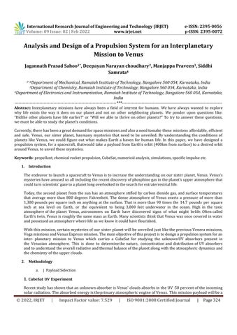
Figure0.1: TrajectoryDesign ii. | ∆v calculation
Weknowthat, Velocityofearthw.r.tsun=29.78km/sVelocityofVenusw.r.tsun=35.10km/sAlso,
CubeSatwithamassof180kgswhichwillbereleasedinapolarorbitatanaltitudeof 75kms its purpose would be to Characterize Venus’ unknown UV absorbers[6].Atradeoffstudywasconductedonthispayloadoption:
a. Scientific Importance: This mission will help determine the nature, concentration and distribution of UV absorbers to understand the overall radiativeand thermal balance of the planet, atmospheric dynamics and the chemistryoftheupperclouds[6].HencetheCubeSatwillprovidehighresolutionUVspectrumofVenus
Our spacecraft has to reach from earth’s orbit (400km above surface) to an orbit around Venus (6126.8km X 50,000km fromthecenterofVenus).AHohmanntransferorbitisusedtotransferbetweentwocircularorbitsfrom basic orbital mechanics[7] AHohmanntransferhasbeenconsideredfromearthtoVenusbecauseingen eral (not always)ittakestheleastamountoffuel.Thisbasicallyinvolvesstartingfromacircularorbitaroundearth,thenper formingaprogradeburntogetintoanellipticalorbitaroundthesunwhile havingescapedearth.Thispointwillbe the apoapsis around the sun (furthest distance from sun). When the spacecraft reaches Venus, it will be at some distancefromitssurface.Here,anotherburn(retrograde)isperformedtomakethespacecraftgetcap turedintoan orbit around Venus. This point around which the burn will be performed will be the periapsis of the elliptical transferorbitaroundthesun.ThispointwillalsobetheperiapsisofanellipticalorbitaroundVenus.
© 2022, IRJET | Impact Factor value: 7.529 | ISO 9001:2008
Volume: 09 Issue: 02 | Feb 2022 www.irjet.net p ISSN: 2395 0072
Certified Journal | Page325
c. TechnologyReadinessLevel:Theinstrumentsforthismissionarereadilyavail able and have also been used by NASA in previous missions.By assessing the above factors, we decided to score each of the tradeoff pointsout of 10. Scientific importance TRL Feasibility Total CubeSat 8 10 9 27 CrashLandingProbe 9 6 7 22 TopologyStudy 8 10 8 26 Table0.1: Trade offstudy

Volume: 09 Issue: 02 | Feb 2022 www.irjet.net p ISSN: 2395 0072 © 2022, IRJET | Impact Factor value: 7.529 | ISO 9001:2008
International Research Journal of Engineering and Technology (IRJET) e-ISSN: 2395-0056
Hohmann Transfer Orbit: Ellipsewithasunatonefocus,point’a’atapoapsisandpoint’p’atperiapsis.Speedat’a’and’p’intransferorbit isgivenby[7] V=√ ( ) (2) rwhere,=distancefromsun2a=2(semi majoraxis) 2a = re + rv =225.46×10⁶km re, rv are the distances of earthand Venus fromthe sun respectively.Usingtheequation1,weget, speedata, Va =27.25km/sspeedatp, Vp =37.85km/s Now, our escape trajectory from earth will be Hyperbolic w.r.t sunHyperbolicexcess velocity, v∞ =27.25 29.78 = 2.53km/s Thenegativesignshows thatthespacecraft will be slowerthan earth w.r.tsun. Using energy equation for hyperbolic trajectories[7], (3) r = R +400km v = √ =11.4 km/s
µs = 1.327 ×10¹¹km3/s2 µe = 3.986 ×10⁵km3/s2 µv = 3.249 ×10⁵km3/s2 Initial orbit around Earth: Theorbitiscircular 400kmfromsurface: v=√ We perform a prograde burn in this orbit at point ’a’ that will get us into ourdesired Hohmann transfer orbit.(elliptical)
Certified Journal | Page326

Page
Therefore,wemustdecreasethevelocityfrom10.66km/sto9.59km/s, ∆v2 =10.66 9.59 =1.07km/s
c. | MassBudgetandStaging Mass Budgeting is the calculation of various mass related parameters for a spacecraft. This includes the dry mass, propellant mass and the payload mass, for each stage. Thus, an overview on the total mass of the spacecraft is obtained usingthisstudy,whichcanbekeptintoaccountwhile designingthevarious subsystemsofthespacecraft. Also,thestudygivesapriorinsightintothemass distributiononeach stageof thespacecraft.Asfarasourproblem statement is concerned, the dry mass for each stage was defined and the mass of payload for our mission was literaturereviewed.Thus,thestudygavethevaluesofthepropellantneededforeachstage.Therefore,mass of each stage can be simply obtained by summing the propellant mass,thedrymass andthepayload mass,ofthatstage. Staging, in simpler terms, is stacking up the various sections of a rocket in a defined or sequential manner. The advantageofstagingisthat itbecomeseas ierfortherockettogettoa desiredorbitalspeedwithoutcarrying any excess mass (such as empty propellant tanks and early stage rockets) with it. So, the fuel/oxidizer of each stage is completelyusedupandthestageisjettisoned.Thus,staging reduces the propellant requirement of the rocket as comparedtoa single stage to orbitspacecraft(SSTO).But thereisa certainlimitup towhichstagesina rocketcan be used to optimize fuel consumption. This limit is calculated in staging study. Thus, there has to be a optimum staging study forit [9][4][14][5]. For our study, the Mass Budget of stages were calculated using Microsoft Excel. Using this, the propellant mass ofeach stageandthe total propellant requiredwas found out. This was simply doneusingtheIdealRocketequation. (4) (5) Where, ∆v =changeinvelocityofthestage(m/s).
© 2022, IRJET | Impact Factor value: 7.529 | ISO 9001:2008 Certified Journal | 327
∆v1 =11.14 7.67 =3.47km/s ∆v1 =3.47km/s Desired orbit around Venus (6,126.8 x 40,000 km): WeknowthatspeedatperiapsisoforbitaroundVenusis9.59km/s(usingvis vivaequation).
When we reach periapsis ’p’ of transfer orbit, it will be an Hyperbolic escape trajectory w.r.t to Venus. So, we havetoperformaretrogradeburntoslowitdown. v = √ v∞ = vp vv/s (v∞ =37.85 35.10) v =10.66km/s
International Research Journal of Engineering and Technology (IRJET) e-ISSN: 2395-0056
Thus, the total ∆v for the mission with buffer for trajectory correction maneuversis, ∆v =∆v1 +∆v2 ∆v =4.6km/s The time of flight in transfer orbit is 120 days. And to ensure that our spacecraft intersectsVenus,Venusmustbe approximately13degreesbehindearthwhilelaunching.
Therefore,ourspacecraftshouldincreasethevelocityfrom7.67km/sto11.14km/s(fromequation1)
Volume: 09 Issue: 02 | Feb 2022 www.irjet.net p ISSN: 2395 0072
Table0.2: Massofpropellantrequiredfordifferentstages
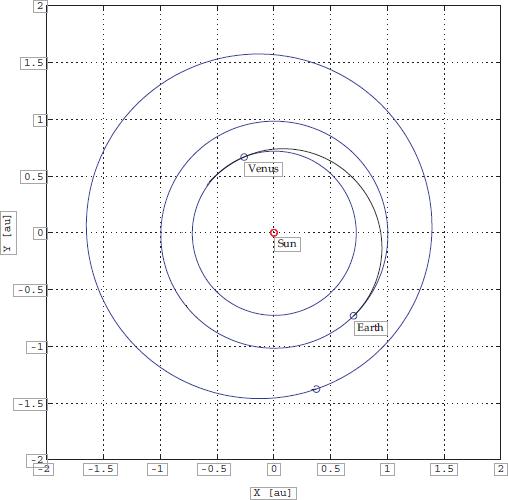
Now, applying the same conditions using the MATLAB program, we get valuesof 5309.4kg for 2 stages and 7011.2kgfor1 stage (seetable 0.2 for reference). Since wehavea function, we’ll calculatethevalue for a seriesof stages. Fornow,atotalof5stageshasbeenconsideredforvalidation. 1stage 2stage 3stage 4stage 5stage Massofpropellant(kg) 7011.2 5309.4 5388.7 6069.3 7143.3
ISO
Fromthegraph0.3,wecanseethatthepropellantrequirementsincreasesafterthethirdstage. Thus, forthedesign ofourspacecraft, 2stageswouldrequirethe least amount of propellant for the mission. Thus, it can be validated from
Volume: 09 Issue: 02 | Feb 2022 www.irjet.net p ISSN: 2395 0072 2022, IRJET | Impact Factor value: 7.529 | 9001:2008 sp =Specificimpulse(s). i =InitialMassofthestage(Kg). f =Finalmassofthestage(Kg).
Figure 0.3: Plot of total propellant mass v/s no. of stages
Thegraph thattwostages requireleastamount of propellant for our mission.
International Research Journal of Engineering and Technology (IRJET) e-ISSN: 2395-0056
©
m
Figure0.2: Masstabulationfor2stages
Certified Journal | Page328 I
m
A MATLAB program was also generated for the study which gave the mass parameters and the optimum staging condition for the required conditions. A graphof Total propellant consumed v/s the total no. of stages was one of the outputs of the program. The input parameters are namely the total no. ofstages, thedry mass condition, total ∆V requirement and payload mass.The best part of using MATLAB program is that, it can be usedfor‘n’stageswithanyuserdefinedinputconditions.ThesamethingdoneinExcelcanbe cometediousfor greater numberofstages, thustheprogramhelpstheuserinit.Weknowthat the payload mass for our mission is 180kg. Also, the dry massofspacecraftis definedas10times the payloadmass.The delta vfor the mission is 4.6km/s and the Isp is 310 s. Thus, applying it in Rocket equation,wegetthePropellantrequirementof5309.4kg.

Certified Journal | Page329
Performance
Volume: 09 Issue: 02 | Feb 2022 www.irjet.net p ISSN: 2395 0072 2022, IRJET Impact Factor value: 7.529 ISO 9001:2008
UDMH +N2O4:
|
1. Density 1180 kg/m3 2. Specificimpulse 310s 3. Temperatureofcombustion 3415C 4. Ratioofspecificheat 1.25 5. Universalgasconstant 375J/kg K 6. Thrust to weight ratio 10 1 103 7. Specificpower 10 2 102 kW/kg 8. Molarproductmass 22.16g/mol 9. O/Fratio 2.6 e. | SystemsEngineeringi.|Thrustdetermination Thrust for the mission is estimated from the
thrust is divided for 8 thrustersandonemainengine. TotalLaunchMass 1245kg Propellants 570kg
LOX + LH2: This liquid fuel has been extensively used by various space research organizations and has very high Isp values. The fuel is also highly cryogenic and haslow density values which will account for a greater fuel mass and a complicatedsystemdesign dueto which wedecided notto usethis propellant[11].
|
1. The chosen propellant was bipropellant liquid rocket. This propellant generally uses a liquid fuel and liquidoxidizer.
d. | PropellantSelection
express
©
2. Liquid propellantrocketscanbethrottledandhavecontrolofmixtureratio;theycanalsobeshutdown,and, with asuitableignitionsystem orself ignitingpropellant,restarted. Allliquid rocketengines havetankageand pipes to storeand transfer propellant, an injector system, a combustion chamber which is very typically cylindrical, and one (sometimes two or more) rocket nozzles. Liquid systems enable higher specific impulse thansolidsandhybridrocketmotorsandcanprovideveryhightankageefficiency.
Characteristics of liquid propellant:
International Research Journal of Engineering and Technology (IRJET) e-ISSN: 2395-0056
Thisbipropellantliquidrocketfuelturnedouttobetheidealfuelfor ourmission.Ithasa300+Ispvalueaswellasa high density which would in turn reduce the mass of propellant leading to an overall reduction in propellant mass [17].
3. After a literature survey and analyses, we finalized the propellant as UDMH (Unsymmetrical Di Methyl Hydrazine) as liquid fuel and N2O4 as liquid oxidizer having properties as mentioned below was selected as it hadalltheusefulparametersreadilyavailable,requiredforfurthercalculations,comparatively. and combustion properties[17]: previous Venus mission[13]. The
| SystemArchitecture
International Research Journal of Engineering and Technology (IRJET) e-ISSN: 2395-0056 Volume: 09 Issue: 02 | Feb 2022 www.irjet.net p ISSN: 2395 0072 © 2022, IRJET | Impact Factor value: 7.529 | ISO 9001:2008 Certified Journal | Page330
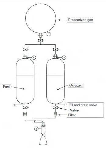
The gas pressure feed system is designed in such a way that it requires minimum number of components to attain minimum weight. Thesystemis de signedtofulfil thesafety,reliability,control and re usability requirements with fewercomponents.Isolation valves shut off a section of the system in case of leak and also pro videsapathfor fluidtoflowduringfillingandventing. Checkvalvesprevent backpressureflowofthefluid. Pyrotechnicvalvesare onetimecutoffvalveactuatedbyasmallelectricpulse[1].Theyprovidesafetytothesystembycut tingoffthefluid duringback pressurization andpreventleakage. Thevalveis added before themanifoldsothat the risk offuel and oxidizer to come in contact before combustion is eliminated. The filter is required to remove dust particles or any other debris before it enters the regulator and the combustion chambers. Pressure transducer and thermocouple are used to measure and monitor the condition of the spacecraft through computers. Fuel and oxidizer for the thrustersarebranchedoutfromthemaintanks. Thepyrotechnicvalveisusedasanemergencycutoffvalveand alsotocontroltheflowofthefluidformaneuvering Figure0.4: Systems architectureofthepropulsionsystem
Component Number of components GasTank(He) 1 Propellant tanks 2 Ballvalves 5 Checkvalves 2 Pyrotechnicvalves 3 Isolationvalve 4 Payload 94kg Propulsion 414N,317s Thrusttoweightratio 0.4
Main
Table0.3: SystemsengineeringThrustrequired=0.4×TotalMass Thrust required = 0.4×6849Thrustrequired=2760N EngineThrust=1960N Thruster’s total thrust = 8 ×100N ii.

f. | EngineDesign i. | MainEngineDesign
firstinordertoperformthefurthercalculationsforthe
INPUT PARAMETERS: • Thrust • Chamber Pressure • ExitPressure • OxidizerFuelRatio • Ratioofspecificheats • Combustion temperature • Characteristic velocity. Alltheabove mentionedparameters
Thefuelandoxidizeraremixedinthecombustionchamberaftertheyareatomizedbypassingthroughtheinjectors. This combustion produces hot exhaust whichispassed through a nozzle toacceleratetheflowand produce thrust. Thus,designofengineplaysaveryimportantrole. Engine design consists of calculating dimensions, specific impulseotherparameters like exit velocity of the engine based on given thrust requirement.Here, we have looked into the combustion chamber, throat nozzle. The injectorhas not been discussed in this report. But a good choice for our requirementwould be a coaxial swirl
Movinginjector.forward,
Figure
International Research Journal of Engineering and Technology (IRJET) e-ISSN: 2395-0056 Volume: 09 Issue: 02 | Feb 2022 www.irjet.net p ISSN: 2395 0072 © 2022, IRJET | Impact Factor value: 7.529 | ISO 9001:2008 Certified Journal | Page331 Venturi 2 Pressuretransducer 3 Thermocouple 3 Filter 3 PressureRegulator 1 Table0.4: Listofcomponentsinsystemarchitecture
We
we will now discuss the input parameters we have and then look into the outputs we have to calculateforonemainengine(1960N thrust)andasmallthruster(100N thrust). The propellant that has been selected is UDMH+N2O4 0.5:RocketNozzle havesomeinputparametersbasedonpropellantdata thrust value asgivenearlierinsection2.5.1 havetobecomputed

International Research Journal of Engineering and Technology (IRJET) e-ISSN: 2395-0056
THRUST Thrustforthemainengineis1960Nand100Nforthethrusterasmentionedinsection2.5.1.
ThecombustiontemperatureTcisthelowesttemperatureinwhichthefuel andoxidizerspontaneouslyignites external sources of ignition inside the combustion chamber. The combustion temperature for UDMH/N2O4 mixtureis3415K.
OXIDIZER TO FUEL RATIO
COMBUSTION TEMPERATURE
Thedata[17].input
Pressure that is maintained inside the combustion chamber for a rocket engineisfairlyhigh,thatisfrom10to200 bar and the pressure with which the exhaust gases leave the nozzle is the exit pressure Pe. From the propellant data[17][2], the optimum chamber pressure Pc is 15 bar. The exit pressure Pe is 1000 Pascalsfrom the reference datafromthepreviousrocketengines.
CHAMBER PRESSURE (Pc) 1.5x
Pascals EXITPRESSURE(Pe) 1000Pascals O/FRATIO 2.6 Gamma(γ) 1.25 COMBUSTIONTEMPERATURE(Tc) 3415K CHARACTERISTIC VELOCITY (C∗) 1720m/s THRUST 1960N Table0.5: MainengineInputs OUTPUT PARAMETERS: •Exitvelocity •ExitMachNumber •TotalMassFlowRate •SpecificImpulse •CoefficientofThrust
CHAMBER PRESSURE AND EXIT PRESSURE
Volume: 09 Issue: 02 | Feb 2022 www.irjet.net p ISSN: 2395 0072 © 2022, IRJET | Impact Factor value: 7.529 | ISO 9001:2008 Certified Journal | Page332 outputparameters.
A certain ratio of oxidizer weight to fuel weight in a combustion chamber will usually yield a maximum performance value. This ratioisdefinedasthe optimum mixture ratio. But in practical applications the optimum mixture ratio is slightly higher than the stoichiometric mixture ratio. This is because a gas which is slightly rich in fueltendstohavealowermolecularweight.Thisresultsinahigheroverallenginesystemperformance. By using this stoichiometric combustion equation C2H8N2 +2N2O4 −→2CO2 +4H2O +3N2 Thestoichiometricoxidizertofuelratiois3.06 For UDMH/N2O4 combination of fuel and oxidizer the optimum O/F ra tio is 2.6 from the propellant parametersvaluesarelistedintheTable0.5 106
International Research Journal of Engineering and Technology (IRJET) e-ISSN: 2395-0056
EXIT VELOCITY Exit velocity is the Velocity with which the exhaust gasses leave the nozzle. Ve = √ Ve=3137.57m/s
EXIT MACH NUMBER
Exit Mach number is the Mach number with which the exhaust gasses leave the nozzle and is calculated using the equation 8. Me = √ ( ) Te =790.83K Me = √ Me =5.15
•Thermodynamic
Volume: 09 Issue: 02 | Feb 2022 www.irjet.net p ISSN: 2395 0072 © 2022, IRJET Impact Factor value: 7.529 9001:2008 AreaRatio values at throat and exit GAS CONSTANT CALCULATION: Fromthepropellantdata[17],weknowthatthevalueof C∗Usingtheformula, √ (6) Thus,wegetthevalueofRas375J/kgK. UsingthevalueofR,wegetmolecularweightas22.161grams.
Certified Journal | Page333 •
AREA RATIO The ratio of the exit area to throat area of a nozzle is termed as the area ratio. As area ratio (AR) increases, the specificimpulseincreases,duetohigherexpansionofhotgaswhichgenerateshighervelocityatnozzleexit. = x( TOTAL MASS FLOW RATE Forcalculating the mass flowrate, three equations are considered. F =(mtotal ×Ve)+ Pee (10) =82.48
|
| ISO
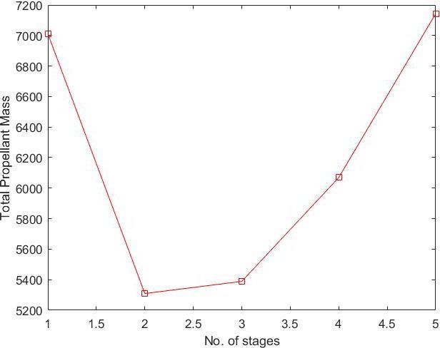
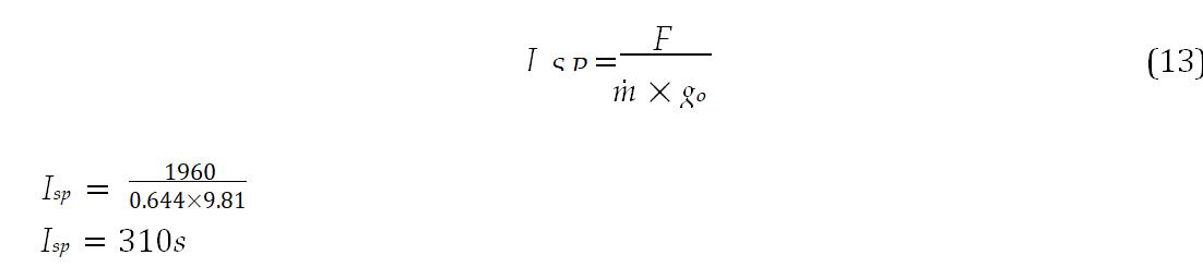
SPECIFIC IMPULSE
International Research Journal of Engineering and Technology (IRJET) e-ISSN: 2395-0056
Mathematically, the Isp is a ratio of the thrust produced to the weight flowof the propellants. The word "specific"justmeans"dividedbyweight".ThespecificimpulseIspisgivenby:
The thrust force of a jet propulsion engine per unit of frontal area per unit ofin compressible dynamic pressure isthethrustcoefficient Cf
COEFFICIENT OF THRUST
|
Themassflowrateforfuelandoxidiserhastobecomputedseparatelyfordetermining the amount of each required inthecombustionprocess. Thus, m fuel =0.3577kg/s moxidizer =0.2862kg/s
Solvingthese three equations which has three unknowns namely Ae, At and m ˙ total weget, Ae =609.1148cm2 At =7.385cm2 mtotal =0.644kg/s
Volume: 09 Issue: 02 | Feb 2022 www.irjet.net p ISSN: 2395 0072 © 2022, IRJET Impact Factor value: 7.529 | ISO 9001:2008
Certified Journal | Page334
Research
Volume: 09 Issue: 02 | Feb 2022 www.irjet.net p ISSN: 2395 0072 2022, IRJET Factor value: 7.529 9001:2008
Engineering and
| Impact
| ISO
Certified Journal | Page335
• Increased frictional losses at the chamber walls reducing nozzle stagnationpressureandhencetheresultant L∗ =80cm 7.38580 c =590.8cm3
While designing the combustion chamber, proper value of L∗ is to be consid ered because an increase in L∗ beyondacertainpointresultsin
International Journal of Technology (IRJET) e-ISSN: 2395-0056
©
Characteristic length (L∗)can beused tospecify the propellant stay timein thechamber. The Characteristic length is defined as the ratio of chamber volumetothenozzlethroatarea. Thiscanbegivenas L∗=AVc t (17)
THERMODYNAMIC VALUES AT THROAT AND PARAMETERS Area CHAMBER VOLUME AND CHARACTERISTIC LENGTH
EXIT CHAMBER CHARACTERISTICS OUTPUT
For sufficient time to ensure complete mixing, atomization, vaporization andcombustion.Thistimeistermedas stay time and has the predominant effect on combustion efficiency The total combustion process, starting from injection of propellants to the completion of chemical reaction and conversion of productsintohotgas,requires finitetimeandvolume.Therateofcombustionandhence thestaytimedependsonpropellantinjectionconditions, combustion chamber geometry and injector design. The combustion volume has a definite effect on combustion efficiencyandisafunctionofmassflow rateofpropellants.
•Higherthrustchambervolumeandweight Createsmoresurfaceareaandhencemorecooling requirements
•
V
ThegraphforThroatdiameter chamber length is plotted as shown in 0.6andthechamberlengthisconsidered tobe13cmafterinterpolatingfromthegraph[3]. Lc =13cm ∗ L =
CHAMBER :
•ChamberVolume •ChamberLength •Chamber
LENGTH
There are 8 small thrusters for altitude control and trajectory correction for our spacecraft, each with a thrust of 100N.Samemethodologyisappliedforthedesignofthesmallthrusters. Theoutputparametersareobtainedusing thesameformulaeasusedearlierandistabulatedasshowintable0.6. Massflowrate 0.03187kg/s Areaattheexit(Ae) 30.1052cm2 Areaatthethroat(At) 0.365cm2 Isp 320.5 Thrust coefficient (Cf ) 1.828 Volumeofthechamber(Vc) 29.2cm3 Diameterofthechamber(Dc) 2.5091cm Length of thenozzle (Ln) 11.752cm Lengthofthechamber(Lc) 5.905cm Mass of the chamber (Mc) 10.816g Massofthenozzle (Mn) 40g Totalmassofsmallengines 406.528g
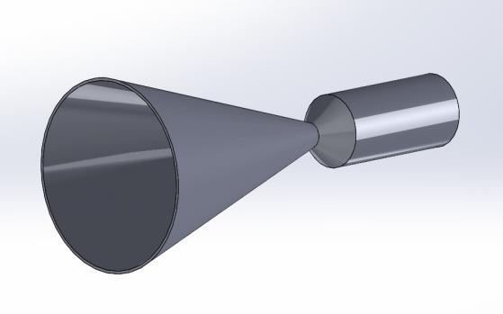
Figure0.7:3Dmodelofmainengine ii. | ThrusterDesign
Table0.6: Outputparametersofthruster
International Research Journal of Engineering and Technology (IRJET) e-ISSN: 2395-0056 Volume: 09 Issue: 02 | Feb 2022 www.irjet.net p ISSN: 2395 0072 © 2022, IRJET | Impact Factor value: 7.529 | ISO 9001:2008 Certified Journal | Page336 Lc Figure 0.6: Plot of Throat diameter v/s chamber length CHAMBER AREA: Ac = Vc Ac =45.4461cm2


International Research Journal of Engineering and Technology (IRJET) e-ISSN: 2395-0056
Figure0.12: PressureFeedSystem i. | Calculationforfeedsystemparameters From thermodynamics, we can say that, the work done in expansion of highlypressurized gas in the gas tank, when the valve is opened, is equal to the workdone by the gas in pushing the propellants to the combustion Thus,chamber.Mathematically it can be writtenas[15]: PgVg = Pp(Vg +(Vf +Vo)) (20) where, Pg =Pressureofthegasinthegastank, Vg =Volumeofthegasinthegastank, Pp =Pressurerequiredtopushthepropellants, Vf =Volumeoffuel, Vo =Volumeofoxidizer.
| ISO
Certified Journal | Page337
Volume: 09 Issue: 02 | Feb 2022 www.irjet.net p ISSN: 2395 0072 © 2022, IRJET | Impact Factor value: 7.529 9001:2008
Feed system in a propulsion system has the function of increasing the Enthalpyof the propellants in the tanks by raising the pressure and supplying them tothecombustionchamberatarequiredmassflowrate.Energyrequired forsuchoperationseithercomefromtankswithhighlypressurizedgasinitorwiththehelp of centrifugal pumps.
Figure0.8: 3Dmodelofthruster g. | FeedSystemsDesign
PgVg = mgRTg (23) For Helium, R = 8.314 =2078.5J/Kg K Substituting thevalues intheequation23, weget, mg =14kg Similarly, thesameapproach canbeapplied to the calculations ofstage2parameters, mf + mo =1334.54 (24) Thus,solving the equations 22and 24, mf =370.7kg and mo =963.84kg Thus, the volumes can be found out as same propellants are used. Vf =0.467m3 and Vo =0.67m3 Substituting values in equation 20,
International Research Journal of Engineering and Technology (IRJET) e-ISSN: 2395-0056
CalculationforStage1 FromMassBudgeting,weknowthatthepropellantrequiredforstage1is3462.6kg. Thus,wecansaythat, mf + mo =3974.82 (21) Here, mf =Massoffueland mo =Massofoxidizer. Also, we know that the ratio in which the fuel and oxidiser burn is 2.6 mo =2.6×mf (22)
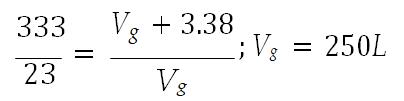
Note:ThePressurevalue333barwasselectedbydoingiterationsondifferent pressurevalues.Pressureof333bar isselectedasthevolumeofgastankneedstobelessandisinverselyproportionaltothePressure. Now,themassofthegasrequiredcanbeeasilyfoundoutusingtheIdealgasequation.
Page
Volume: 09 Issue: 02 | Feb 2022 www.irjet.net p ISSN: 2395 0072 © 2022, IRJET | Impact Factor value: 7.529 | ISO 9001:2008 Certified Journal | 338 0.004
Solvingequation21and22,weget mf =1104.1kgand mo =2870.7kgNow, ρf =793kg/m3 and ρo =1440kg/m3 Thus, Vf =1.39m3 and Vo =1.99m3 Also,weknowthat Pp =23bar, Tg =288K Substitutingthevaluesinequation20,weget,
The designofHelium tanks should be such that it should withstand thehighly pressurized gascontaining init. Thus,thethicknessofthetankandthematerialselectionforthetankplaysavitalroleinit. The thickness of the spherical tank is calculated for various materials. The material with best strength and giving leastmassforthetankisconsideredforthedesign. Fromthecalculationsearlier, it wasinferredthatthevolumeof the tank for stage 1 should be 250L and 85.3L for stage2. Asweareusingsphericaltanksforsimplicity, Now,substitutingthevaluesforvolumeintheequation,weget, ri =0.39m (Innerradiusforstage1) ri =0.27m (Innerradiusforstage2) Now, that we have the internal radius of tank, the thickness of the tank would be the difference of the outer radius and inner radius. thickness = ro ri ThethicknessofsphericaltankasafunctionofPressure,radiusandYieldstrengthisgivenas[10]
2.8.2 |
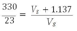
Vg =85.3L Bysubstitutingthedataineq23, mg =4.7kg Thus,theparametersofthe gas, for the feed system, are tabulated asfollows: Stage 1 Stage 2 Gas Helium Helium Pressure(bar) 333 330 Volume(m3) 0.25 0.085 Temperature(K) 288 288 mass(kg) 14 4.7 Table0.9: Feedsystemparameters
International Research Journal of Engineering and Technology (IRJET) e-ISSN: 2395-0056
Volume: 09 Issue: 02 | Feb 2022 www.irjet.net p ISSN: 2395 0072 © 2022, IRJET | Impact Factor value: 7.529 | ISO 9001:2008
Certified Journal | Page339
DesignofHeliumtanks
|
Material T(MPa) Pressure(MPa) ri(m) thickness(mm) r f (m) Mass(kg) Al5052 230 37.5 0.273 35.14 0.308 100.05 Al3003 130 37.5 0.273 62.17 0.335 197.93 Ti6Al 4V 880 37.5 0.273 8.72 0.281 37.37
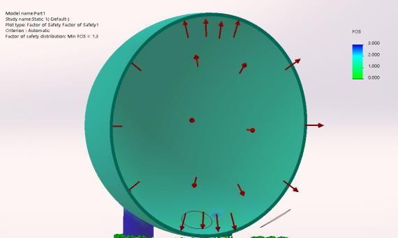
As we can see from the table 0.11, Ti 6Al 4V gives least mass among the others.Thus,weselect itforstage2tanks as Thus,well.the tanks finalised has the following parameters: Stage 1 Material Mass of tank(kg) Volume of tank(L) Pressure(bar) Min. F.O.S Ti6Al 4V 109 250 375 1.3
International Research Journal of Engineering and Technology (IRJET) e-ISSN: 2395-0056
ri =Innerormeanradiusofthetank.T=Yieldstrengthofmaterial. Calculations were done using the equation 25 for different materials hav inggoodstrength to weightratioand goodtensilestrength. Material T(MPa) Pressure(MPa) ri(m) thickness(mm) r f (m) Mass(kg) Al5052 230 37.5 0.39 50.20 0.44 291.7 Al3003 130 37.5 0.39 88.81 0.48 577.1 Ti6Al 4V 880 37.5 0.39 12.46 0.40 109
Volume: 09 Issue: 02 | Feb 2022 www.irjet.net p ISSN: 2395 0072 © 2022, IRJET Impact Factor value: 7.529 | ISO 9001:2008 Pressurein the tank. t = 1.5× P × ri 2× T (25)
Certified Journal | Page340 Pwhere,=Max.
Table0.13: Stage 2Heliumtank
Table0.12: Stage 1Heliumtank Stage 2 Material Mass of tank(kg) Volume of tank(L) Pressure(bar) Min. F.O.S Ti6Al 4V 38 85 375 1.4
Table0.10: Tankparametersfordifferentmaterials(stage1) SinceTi6Al 4Vhastheleastmassandhasgoodstrength,weselectthematerialforthestage1heliumtank. Similarlyweapplythesameapproachtothedesignofthestage2tanks.
Table0.11: Tankparametersfordifferentmaterials(stage2)
Volume: 09 Issue: 02 | Feb 2022 www.irjet.net p ISSN: 2395 0072 © 2022, IRJET | Impact Factor value: 7.529 9001:2008
[7] HowardDCurtis.Orbitalmechanicsforengineeringstudents Butterworth Heinemann,2013.
| ISO
[6] V Cottini, S Aslam, E D’Aversa, L Glaze, N Gorius, T Hewagama, N Ig natiev, and G Piccioni. Cuve cubesat uv experiment: Unveilvenus’uv absorberwithcubesatuvmappingspectrometer. InEuropean Planetary ScienceCongress,Riga,Latvia,volume11,pages771 772,2017.
International Research Journal of Engineering and Technology (IRJET) e-ISSN: 2395-0056
[9] HH Hall and ED Zambelli. On the optimization of multistage rockets. Journal of Jet Propulsion, 28(7):463 465,1958.
3. Conclusion A Propulsion system for a mission to Venus was designed along with the choice of payload. The mission profile including thetrajectoryanddelta vrequirementswereworkedupon.Themassforeachstagewascalculatedand based on the stage optimization study, the spacecraft was designed to be two staged due to its less fuel requirement. Different propellants were studied for the spacecraft and based on the trade off study, UDMH + N2O4 were considered. The thrust required for the mission was reviewed and a thrust of approximately 2760N was calculated.Thefeedarchitectureforthespacecraftwasdesignedwithleast numberofcomponentsandmaximum safety. Themainengine andthrusters forthespacecraftweredesignedandwerefoundtobe 93percentefficient. Thepropellantstanksforboththestagesofthespacecraftweredesignedwithpis tontypeofPMD.Gaspressure typeoffeedsystemwasdesignedwithhighly pressurizedheliumgastanks. Thus,thespacecraftcaneasilytake apayloadof180kgfromearth’sorbit(around400kmfromearth’ssurface)toadesiredorbitaroundVenus(6126.8 x40,000km).
REFERENCES: [1] Laurence J Bement and Morry L Schimmel. A manual for pyrotechnic design, development and qualification. 1995.
[10] David H Huang and Dieter K Huzel. Modern engineering for design of liquid propellant rocket engines AmericanInstituteofAeronauticsandAstronau tics,1992.
[4] David N Burghes. Optimum staging of multistage rockets. International Journal of Mathematical Education in Science and Technology, 5(1):3 10, 1974. [5] Ezgi Civek Cos¸kun and Kemal Özgören. A generalized staging optimiza tion program for space launch vehicles. In 2013 6th International Conference on Recent Advances in Space Technologies (RAST), pages 857 862. IEEE, 2013.
[8] Anthony Freeman, Suzanne E Smrekar, Scott Hensley, Mark Wallace, Christophe Sotin, Murray Darrach, Peter Xaypraseuth, Joern Helbert, and Erwan Mazarico. Veritas: a discovery class venus surface geology and geophysicsmission. 2016.
Figure0.13: Staticanalysisofstage 1heliumtank(left)Figure0.14: Staticanalysisofstage 2heliumtank(right)
[2] RobertBraeunig.Propellantcombustioncharts.[http://www.braeunig.us/space/comb.htm].
[3] RobertBraeunig.Rocketpropulsion.[http://www.braeunig.us/space/propuls.htm#engine].
Certified Journal | Page341

[18] Mike Wall. Rocket lab’s plan to search for life on venus in 2023 just got more exciting, September 2020.[https://www.space.com/rocket lab venus life hunting mission.html].
[12] Sandeep Raheja. Pressure vessel thickness calculation. [http: //docs.codecalculation.com/mechanical/pressure vessel/thickness calculation.html].
[13] P Sivac and T Schirmann. The venus express spacecraft system design.VenusExpress,2004. [14] M Subotowicz. The optimization of the n step rocket with different con struction parameters and propellantspecificimpulsesineachstage.Jour nalofJetPropulsion,28(7):460 463,1958.
[15] GeorgePSuttonandOscarBiblarz. Rocketpropulsionelements JohnWiley&Sons,2016. [16] PEUneyandDAFester.Materialcompatibilitywithspacestorablepro pellants.designguidebook. 1972. [17] MarkWade.Propellantdescriptionofudmh+n2o4.[http://www.astronautix.com/n/n2o4udmh.html].
International Research Journal of Engineering and Technology (IRJET) e-ISSN: 2395-0056
Volume: 09 Issue: 02 | Feb 2022 www.irjet.net p ISSN: 2395 0072 © 2022, IRJET | Impact Factor value: 7.529 | ISO 9001:2008 Certified
Journal | Page342
[11] Pascal Pempie,Thomas Froehlich, andHilda Vernin. Lox/methaneandlox/kerosenehighthrust enginetrade off.In37thJointPropulsionConfer enceandExhibit,page3542,2001.