Gautham Manoj 1Research and Development Engineer, Forbes Marshall Pvt. Ltd., Pune, India.
© 2022, IRJET | Impact Factor value: 7.529 | ISO 9001:2008 Journal |
Certified
EFFECT OF CRITICAL VOLUME AND ENCLOSURE SURFACE AREA IN A BIMETALLIC STEAM TRAP RESPONSE
Key Words: SteamTrap,Bimetal,CFD,NaturalConvection, Energy conservation, Heat transfer, Critical volume, Trap response.
Abstract Steam traps are valves that are used in industries that use steam for their processes, to remove condensate generated in steam line and not letting steam out. This helps in keeping the process efficiency high and preventing steam discharge. Thermostatic bimetallic steam trap consideredhere works based on the principle of thermal expansion. Exposure to steam and higher temperature stimulates the sensing elements to expand close the valve. Even though the element expansion is directly defined as a parameter of temperature in all designs, the control/critical volume around the element as well as the trap external surface area plays a crucial role in the trap response. A mathematical model comprising of the effect of both the mentioned parameters on sensing element response was developed. A heat transfer CFD model was developed to find out the heat available within the control volume & heat lost through the trap body to the atmosphere to calculate whether the sensing elements receive a satisfactory amount of energy to actuate. Through this exercise, the control/critical volume around the elements and trap body was optimized for satisfactory performance.
1.INTRODUCTION
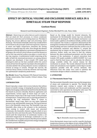
Thethermostaticbimetallicsteamtrapusesthetemperature of steam and condensate to operate. The bimetal alloy elements expand upon coming in contact with high temperature steam and condensate and this expansion is convertedtovalveoperationbyclosingthevalveseat.The schematicofthemechanismisasshownin Fig 1
Steamtrapsplayamajorroleineveryindustrythatutilizes steamtotransferenergy,inkeepingtheprocessefficiency highbydischargingcondensateformedfromthedistribution linebasedonprocesscriticality.Basedonapplicationand requirements, various types of steam traps are used. A thermostaticsteamtrapisthetrapsworksontheprinciple oftemperature.Temperatureactsasadrivingparameterin actuating the trap mechanism. When it comes to thermostatic steam traps, there are two types, balanced pressuretrap,andbimetallicsteamtrap.Thetrapofinterest here is the bimetallic steam trap. The bimetallic trap uses bimetallic alloy strips as the actuator in the mechanism. Upon coming in contact with steam and saturated condensate, the bimetallic element expands which in turn actuatesthevalveandclosesthesame.Themechanismstays closed until the temperature of condensate reaches a set subcooled temperature & discharges condensate at a set temperature.Thisresponseensuresthattheprocessutilizes thesensibleheatavailableandpreventsenergywastageand increasesprocessefficiency.
International Research Journal of Engineering and Technology (IRJET) e ISSN: 2395 0056 Volume: 09 Issue: 02 | Feb 2022 www.irjet.net p ISSN: 2395 0072
Fig 1:Bimetallicsteamtrapschematic Everythermostaticsteamtrapissetforaspecificdischarge temperatureknownasthedegreeofsub cooling(DOS).The thermostaticbimetallicsteamtrapholdsbackthesteamand
Initialprobingandtestsconfirmedthatthesurfaceareaof the mechanism enclosure and effective CV around the mechanism had an impact on the response. Based on this inference, further study was done to find the relation between the above mentioned parameters and the actual response of the mechanism. A natural convection heat transfer CFD model available in ANSYS FLUENT 16.1 was used to find the heat losses and to calculate the effective energy available within the control volume for the mechanism to actuate. The results obtained from the CFD studyandcalculationsweretogetherusedtofigureoutthe expansion possible with the current elements. The inferences from this study were used to optimize the mechanismdesigntoobtainasatisfactoryresponse.
2. 2.1LITERATUREThermostatic Steam Trap
***
Based on the design model for bimetal elements, the mechanism for the\bimetallic steam trap was calculated, designed, and developed. The developed mechanism was testedunderaplethoraofconditionsinitially,andtheresults wereanalysed.Theresultsorresponsesobtainedfromthe testingdoneandtheoreticalmodelsweredistinctlydifferent.
Page306

Basedonthetypeofelement,theresponseparametersvary. Theresponseparametersoftheelementsuchasmechanical forcegeneratedanddisplacementgeneratedarefunctionsof temperatureandgeometricaldimensionsoftheelement.For thethermostaticbimetallicsteamtrapconsideredhere,the MechanicalEquivalentDisplacementtemperature,ofshapeoftheelementisacantilever.Theresponseparametersthecantileverelement,whichareafunctionofareasfollowsgenerated(eq.1)ThermalForces(eq.2)Forcegenerated(eq.3)Where,a=SpecificdeflectionoftheBimetalelement.L=Lengthofthecantileverelement(m).w=widthofthecantileverelement(m).t=thicknessofthecantileverelement(m).
Inthevalvemechanism,bimetalexpansionforcesorthermal forces(FT) generate thevalve closingforce. There are two typesofbimetallicsteamtrapmechanisms,pressure to close, andpressure to open.Inthepressure to closeconfiguration, thepressureaddsuptotheclosingforceandhelpsinclosing the valve. On the other end, in pressure to open configurations,thepressureforcesresisttheclosingforces generatedbybimetallicelements.Compressionspringsare used in a few designs, usually in pressure to close configurations,tokeepthevalveopen.Thisnotonlyensures the always open valve configuration but also defines from whattemperaturetheelementsstarttodeflectasthespring cancelsouttheinitialforcesgeneratedbybimetalelements.
2.2 Bimetallic Element
Equationsforcalculatingmechanical forcesarederivedby substitutingthedisplacementequationinthethermalforce equation.Thethermalforceisequivalenttotheloadrequired to bend a cantilever beam and deflect it by δ (D). And the responseconsideringTheofhaverange.abetterelementrangeTheandvalueofspecificdeflectionvariesfordifferentelementshapesmaterials.bimetalelementhasaworkingoroperatingtemperatureunderwhichtheelementwillnotfailordamage.Themustbeoperatedwithinthatlimitrangetoensureperformance.However,theresponseisonlylinearforsmallerrangewhichisasubsetoftheentireoperatingPostthat,displacementincrementsarenonlinearandalowerincrementwhichgraduallyflattensoutbecausethechangeinspecificdeflection(a).elementconsideredforthisapplicationwasselectedthelimitandlinearityrangetoensurebetterandsafetyofthedesign.
International Research Journal of Engineering and Technology (IRJET) e ISSN: 2395 0056 Volume: 09 Issue: 02 | Feb 2022 www.irjet.net p ISSN: 2395 0072
© 2022, IRJET | Impact Factor value: 7.529 | ISO 9001:2008 Certified Journal | Page307 condensateuntilthetemperaturedropsandreachesthisset DOS.Oncethecondensatetemperaturedropsbelowtheset DOS,themechanismandelementscontracttoopenthevalve seatanddischargethecondensate.ThissettingforDOSshall be given based on the process and its criticality. This is to ensurethatenergyconsumptionfromsteamandtheprocess efficiencyismaximized.
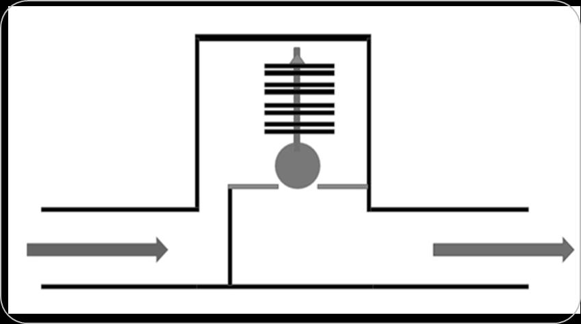
Bimetallicelementorstripconvertstemperaturechange(ΔT) intomechanicalworkbyexpandingandexertingforce.These elements/stripsaremadeofstackingtwoormoredissimilar alloys with different thermal expansion coefficients. Upon comingincontactwithaheatsource,theelementexpandsin a controlled manner due to differential expansion of the componentalloys.Thehigherexpansionside(HES)expands morecomparedtotheLowexpansionside(LES)togenerate acontrolleddeflectionasshownin Fig.2 There are various shapesofelements thatareavailableor commonlyused.Thestandardorcommonlyusedshapesare Cantilevertypeelement fixedatoneend Simplysupportedbeamtypeelement supportedat bothends U shapedelement fixedatoneendofU SpiralorHelixtypeelement Disctypeelement Fig 2:
BimetallicelementResponse
E=Young’smodulusoftheBimetalelement(N/m2).
3. DESIGN CALCULATION & CHARACTERISTICS
The bimetal elements are usually stacked in a particular fashion to maximize expansion and mechanical forces and facilitatetheactuationofthevalve.Designcalculationwas done for the mechanism, considering the bimetal element used, to define the stacking as well as the mechanism responsecharacteristics.


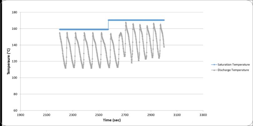
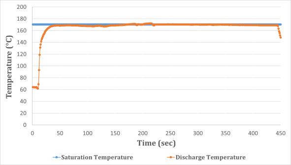
Anactualprototypeofthemechanismwasdevelopedbased ontheinputsfromthedesigncalculationsandthesamewas tested. Though the theoretical response obtained and calculation results were satisfactory, when the actual prototypedevelopedwastested,theresponseobtainedwas notuptothemark.Leakageofsteamwasobservedfromthe steamtrap.Thetraptestresponseisasshownin Chart 4.The graphshowsthatthecondensatewasnotbeingdischargedat asubcooledtemperature.Theobservationwasthatelements weren’tgeneratingenoughexpansionorforcestoovercome thepressureforcesneededtoclosethevalve.Furtherstudy and analysis were done to find the root cause for this problem.
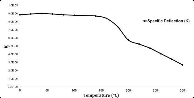
The major parameter that controls the mechanism characteristics is the specific deflection constant of the bimetallic element. To identify the relation of variation between the constant and temperature, the element was tested at various temperatures, and displacements were measured. The relation between the specific deflection constantandtemperatureisasshownin Chart 1 Thespecific deflection is the proportionality constant of thermal expansion,D,andthermalforces,FT generatedbyabimetal element, and is inversely proportional to temperature at higher temperatures. The design calculation was done to identifythemechanismresponsecharacteristicsconsidering this.Theintendedfunctionofabimetallicsteamtrap,orany thermostatic steam trap, is to discharge condensate at a specific degree of subcooling. This implies that for a given operating range, the response characteristics follow the saturationcurveofsteam water.So,foragivenpressureif waterexistsatsaturationtemperature,thebimetallicsteam trapistodischargecondensateatafixedlowertemperature thansaturationtemperature;hencearesponsecurvesimilar tothesaturationcurvewithafixedoffset.
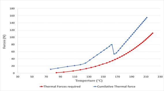
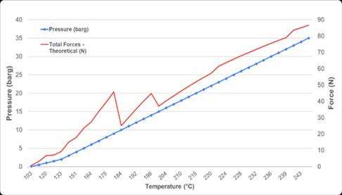
Chart 3:Trap TheoreticalvsRequiredForce
The mechanism is placed inside an enclosure and body as shownintheroughschematic Fig 1. Thenormallyopentrap bringshotcondensateandsteaminsidetheCV,aroundthe mechanism.Uponcomingincontactwiththehotmedium,the mechanism expands and closes the valve seat. The valve opensonlywhenthecondensateintheCV coolsdownand dropsbelowthesettemperatureorDOS.Thisistheexpected responseofathermostaticbimetallicsteamtrap.
Chart 1:Bimetal SpecificdeflectionvsTemperature
Thereasonfortheleakageofthesteamtrapwasassumedto betheexcessiveheatlossfromtheenclosureandinsufficient heatenergywithintheenclosurefortheelementstoexpand.
A natural convection heat transfer CFD study of the trap enclosure was used to validate the aforementioned
© 2022, IRJET | Impact Factor value: 7.529 | ISO 9001:2008 Certified Journal | Page308
International Research Journal of Engineering and Technology (IRJET) e ISSN: 2395 0056 Volume: 09 Issue: 02 | Feb 2022 www.irjet.net p ISSN: 2395 0072
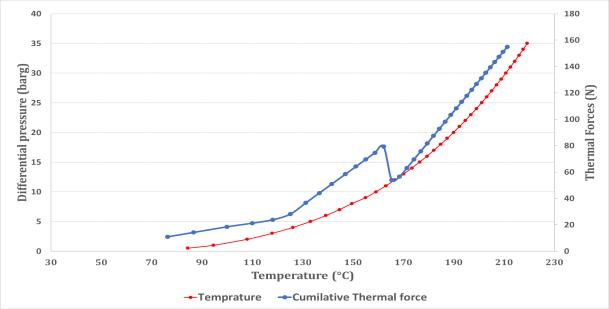
The response of this bimetallic steam trap was calculated usingbimetaldesignequations,(eq.1),(eq.2),&(eq.3).The theoretical response of the mechanism was plotted along withthesaturationcurveofsteam/waterasshownin Chart 2. This graph shows a staggered but nonlinear response similar to the saturation curve. Along with this, the theoreticalforcesgeneratedbythemechanismandtheforce required for the satisfactory operation of the trap are as shownin Chart 3 Chart 2:TrapMechanism TheoreticalCharacteristics
Chart 4:TrapMechanism Testresponse 4. THEORETICAL MODEL & SIMULATION 4.1 Pre-Processing
International Research Journal of Engineering and Technology (IRJET) e ISSN: 2395 0056 Volume: 09 Issue: 02 | Feb 2022 www.irjet.net p ISSN: 2395 0072
TheNusseltNumberequationsfortheaforementionedtypes of surfaces for both laminar and turbulent flows are as Thefollows.Nusseltnumberequationforaflathorizontalplatewith thehotsurfaceinsideandthecoldsurfaceoutside(eqis:(eq.4).5)
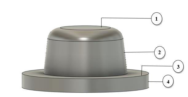
hypothesis.Thishelpedtofindtheeffectiveheatlossfromthe systemandcalculatetheenergyavailableforthemechanism to Theactuate.enclosure that covers the steam trap mechanism isas shownin Fig 3. ThenaturalconvectionCFDsimulationwas done for selected operating conditions from the entire operatingrangeof0bargto35barg.Theselectedpointsare: 1 barg 10 barg 20 barg 35 barg
Thecoverisshownin Fig 3 wasdividedinto4partssuchas: 1. TopHorizontalsurface 2. Cylindricalsurface 3. HorizontalFlangesurface 4. Cylindricalflangesurface
The Nusselt number equation for the outer surface of a cylinderis: (eq.6) Hereinthisequation, (eq.7)
Fig 3:Bimetalsteamtrapcover The temperature distribution of the above 4 surfaces was identifiedthroughthesimulation.Thisinturnwasusedto calculate the convective heat transfer coefficient and heat dissipationfromthesurfaces.Theconvectiveheattransfer coefficientwascalculatedasshownbelow.
© 2022, IRJET | Impact Factor value: 7.529 | ISO 9001:2008 Certified Journal | Page309
GrashoffWhere,’sNumber, GrL = (eq.8) PrandtlNumber Pr = (eq.9) Where, g =Accelerationduetogravity(kg.m/s2)
β =Coefficientofthermalexpansion(1/°C) Twall =WallTemperature(°C) T∞ =AtmosphericTemperature(°C) L =VerticalLength(m) v =KinematicViscosity(m2/s) CP =SpecificHeat(J/kg.°C) μ =Dynamicviscosity(N.s/m2) k =ThermalConductivity(W/m.°C)
ANSYSFLUENT16.1,wasusedtosimulateandcalculateheat lossesfromtheenclosure.Theflowconditionsconsidered fortheCFDsimulationwere3D,steady&laminar(Rayleigh’s number<107).Theresultanttemperaturedistributionon the enclosure outer surface (Tout) and convective heat transfer coefficient (hc) was solved based on the conservation equations of mass, momentum, and energy. Theequationsare: ContinuityEquation: (eq.10) MomentumEquation:


Pressure
Cover
Fig 3 tocalculate theconvectiveheat transfer coefficient. The temperature values of each highlighted surfaceasshownin Fig 3 areasmarkedin Fig 6 Inlet (Face2&3asshowninFig.4) 0 barg (Opentoatmosphere) Outlet (Face1asshowninFig.4) 0 barg (Opentoatmosphere) inner Wall (Face4asshowninFig.4) Saturation temperature foreachpressurepoint
Pressure
Fig 6:CFDStudy TemperatureDistribution FromtheTout valuesobtainedfromtheCFDstudy,specific astemperaturevalueswereisolatedforthehighlightedsurfacesshownin
Fig -5:CFDStudy Temperature&VelocityFields
International Research Journal of Engineering and Technology (IRJET) e ISSN: 2395 0056 Volume: 09 Issue: 02 | Feb 2022 www.irjet.net p ISSN: 2395 0072 © 2022, IRJET | Impact Factor value: 7.529 | ISO 9001:2008 Certified Journal | Page310 (eq.11) EnergyEquation: (eq.12) The material properties and boundary conditions are mentionedinthetablesgivenbelow: Table 1:CFDsimulationmodel&details HeatTransfer Natural Convection (Energy EquationEnabled) FluidMedium Air Density model for medium Incompressible IdealGas(Inversely Proportionaltotemperature) FlowType Laminar(Rayleigh’sNumber<107) Solid Body Material Stainlesssteel Theboundaryconditionsappliedonthegeometrytakenfor CFDstudiesareaddedbelow.Thereferenceisasshownin Fig 4: Table 2:CFDsimulationboundaryconditions Fig -4:CFDSetup(BoundaryConditions) Table 3:CFDPressure&Temperaturepoints. (barPressureg) (°C)Temperature 1 120.4 10 184.1 20 214.9 35 244.2 TheoperatingconditionsforwhichtheCFDstudywasdone arementionedin Table 3 4.2 Results
Thetemperaturedistributionandvelocityfieldresultsfrom theCFDstudyforoneselectedoperatingconditionfromthe range(Table 3),i.e.,1barg,areasshownin Fig 5 & Fig 6.
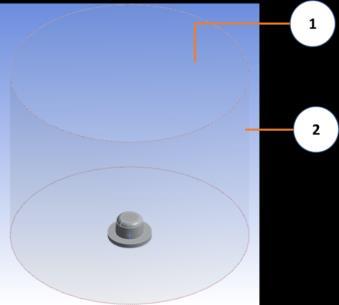

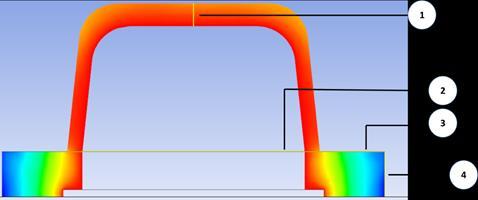


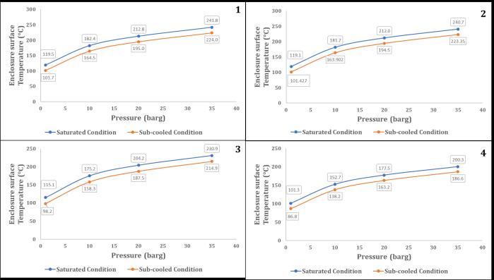
Chart 5:SurfaceTemperature SaturatedvsSubcooled condition(Foroperatingrange)
ThestudywasconductedforalltheselectedpointsandTout values were identified for all those conditions on all the faces/nodes. This study was conducted for cases with saturatedcondensateflowingthroughthetrapaswellasthe case with subcooled condensate and the Tout values were identified for both cases. The Tout variation for the entire operatingrangeforbothsaturatedandsubcooledconditions wascollectedandisasshownin Chart 5.Theconvectiveheat transfercoefficientsatthesurfaceswerecalculatedforallthe selected study points from the entire range, using the fortemperaturedistributionresultsobtainedfromtheCFDstudybothsaturatedandsubcooledconditions.
International Research Journal of Engineering and Technology (IRJET) e ISSN: 2395 0056 Volume: 09 Issue: 02 | Feb 2022 www.irjet.net p ISSN: 2395 0072
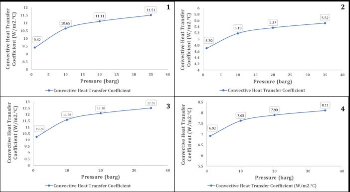
The average convective heat transfer coefficient for the highlighted surfaces was calculated from the Tout results obtainedfromtheCFDstudy.Theconvectiveheattransfer coefficientcalculatedforallfacesasper Fig.4 atoneofthe operatingpoints,i.e.,1bargis:
Chart -6:EnclosureConvectiveheattransfercoefficients
TSubcooled =Outerwalltemperatureatthesubcooled conditionforwhichtrapisset(Dischargetemperature)
Theconvectiveheattransfercoefficientscalculatedasperthe (eq.13) for the entire operating range and the highlighted surfacesareasshownin Chart 6 Thisshowsthechangein the average convective heat transfer coefficient of the externalsurfaceoftheenclosureoveragivenpressurerange. And overall average convective heat transfer coefficient of enclosuresurface. Fromtheconvectiveheattransfercoefficientvaluesobtained, the effective heat flux or heat loss from the enclosure was calculatedusingtheformula: EffectiveHeatlossFlux: (eq.14) Where, Δhc = Average heat transfer coefficient from Tout results obtained for both saturated and subcooled conditionsTSaturated=Outerwalltemperatureatinitialcondition (Saturatedsteam/condensateinsidetheenclosure)
Theconvectiveheattransfercoefficientwascalculatedbased onthe Convectiveequation:heattransfercoefficient: (eq.13) Where,Nu L =NusseltNumber K=Thermalconductivity D=Characteristiclength(Changesforeachsurfacebased onitsorientation)
Table 4:Avg.Heattransfercoefficientsoffaces
© 2022, IRJET | Impact Factor value: 7.529 | ISO 9001:2008 Certified Journal | Page311


© 2022, IRJET | Impact Factor value: 7.529 | ISO 9001:2008 Certified Journal | Page312
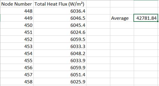
Table -5:HeatfluxvaluesatoutersurfacenodesfromCFD
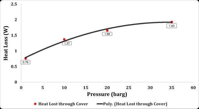
Chart 7:TotalheatlossfromCVvsPressure
International Research Journal of Engineering and Technology (IRJET) e ISSN: 2395 0056 Volume: 09 Issue: 02 | Feb 2022 www.irjet.net p ISSN: 2395 0072
MassofcondensateinsideCV: m = V. ѵ (eq.17)
Usingtheconvectiveheattransfercoefficientobtainedfrom thesimulationandusingtheformula(eq.14),theheatfluxat eachnodeoftheoutersurface/wallwascalculatedandthe averageofthesamewastakentoapproximatethetotalheat lost. Table.5 showstheheatfluxcalculatedusingthepost processorforoneoftheselectedcasesfromtheoperating range(i.e.,1barg) The above study, calculation, and results were for one selected operating point from the entire operating range. Thesamewasrepeatedforalltheselectedoperatingpoints fromtheoperatingrange.TheCFDstudyforsaturatedand subcooled conditions was done for these selected points using a parametric model and convective heat transfer coefficientswerecalculated.Thesevalueswerethenusedto calculatetheeffectiveaverageheatfluxfromthecover.Heat lossfromthecoverthroughouttheentireoperatingrange wascalculatedfromtheheatfluxvaluesusing (eq.15)and theresultsareasshownin Chart 7
Totalcalculated.heatavailablewithinCV: Qavailable = ΔH . m (eq.16)
SpecificEnthalpyDifference: ΔH = Hsaturated - Hsubcooled (eq.18) Where, ѵ Specific volume of condensate at operating conditionsV Volumeinsidetheenclosure Hsaturated Specificenthalpyatsaturationconditions Hsubcooled Specificenthalpyatsubcooledconditions
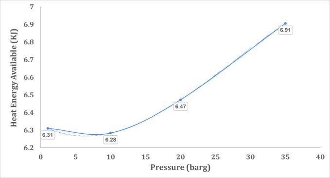
Chart 8:TotalHeatenergyavailablevsPressure
The critical volume around the mechanism or effective volumeinsidetheenclosureistheheatenergysourceandto find the available energy, the total volume inside the enclosure was calculated, and using specific enthalpy of saturated condensate and subcooled condensate, the heat energy available for the mechanism for actuation was
The variation of energy available within control volume acrosstherangeisshownin Chart 8. Theheatrequiredforthebimetalelementswascalculatedby couplingthe(eq.1)forbimetalexpansion,withthespecific heatequation.Thebimetalexpansionequationisexpressed asafunctionoftemperature.However,thetemperatureis not a conserved parameter. Hence, the equation was expressedasafunctionofheatenergytofindtheequivalent heatenergyrequiredtogeneratesufficientvalvetraveland closingforces.
TotalHeatlossfromcover: Q = Ǭ . A (eq.15) Where,Q=Heatloss(W) Q=Heatflux(W/m2) A=Enclosuresurfacearea(m2)
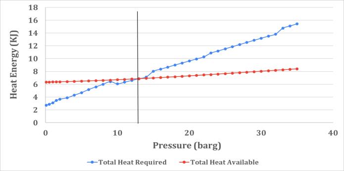
Theresultsfromthestudyshowthattheavailableenergyis less than the required heat energy for a major part of the operatingrange.Thislackofenergywithintheenclosureis the reason for the leakage from the steam trap. And the majorreasonforthejumpinenergyrequirementsathigher operating temperatures is the reduction in the specific deflection constant at higher temperatures as shown in Chart 1 Basedonthestudy,ithasbeenprovedthattheactualheat energyavailableislimitedandhencethemechanismmust be designed considering energy as a parameter and not temperature.Mechanismredesignforagivenenclosurethat meets other design requirements such as pressure vessel norms and strength calculation was done to obtain a satisfactoryresponse.
Based on the study conducted and calculations done, the actual available energy within the control volume for the mechanismwasfound.Theenclosurearoundthemechanism isapressurepart/vesselandhencethedesigncalculations forthatparticularcomponentdefinethedimensionsofthe same. Hence the mechanism was redesigned and the actuating elements were restructured and stacked accordingly for this particular cover to obtain ample expansion,valvetravel,andvalveclosingforces.
The designcalculationforthemechanism wasdoneagain andthenumberofelementsandspringwasredefined.Based onthenewmechanismdefinition,theoreticaltrapresponse characteristics were plotted and thermal forces were checked.Thetheoreticalresponsesobtainedareasshownin Chart 10 & Chart 11.
Chart 11:RedesignedMechanism TheoreticalForce generatedandrequired.
Consideringtheforces,themechanismmustgenerateand thedisplacementsitmustproducetoperformsatisfactorily, theheatenergyrequiredwascalculatedusing(eq.19).The total energy required for the satisfactory response of the bimetalmechanismandheatlossesfromtheenclosurewas comparedwiththeenergyavailableisasshownin Chart 9
5. CORRECTIVE MEASURE
© 2022, IRJET | Impact Factor value: 7.529 | ISO 9001:2008 Certified Journal | Page313 (eq.19)
Chart 10:RedesignedMechanism Theoreticalresponse
International Research Journal of Engineering and Technology (IRJET) e ISSN: 2395 0056 Volume: 09 Issue: 02 | Feb 2022 www.irjet.net p ISSN: 2395 0072
The new mechanism wasdevelopedandtestedat various functionaltestconditionsandactualtestdatawascollected tocheckandvalidatethemechanismdesign.Themechanism response was satisfactory and the discharge of the condensatewasatanaveragedegreeofsubcoolingandno steam discharge was observed. The response obtained throughtestingfortheredesignedmechanismforoneofthe testcasesisasshownin Chart 12.Basedontheredefined mechanism’stheoreticalresponseandtestresultsobtained, thefinalmechanismdesignwasfoundtobesatisfactory.
Chart 9:TotalHeatavailable&requiredvsPressure


6. CONCLUSIONS
Journal
Chart
© 2022, IRJET | Impact Factor value: 7.529 | ISO 9001:2008 Certified | Page314 -12:
Anaturalconvectionheattransfersimulationmodel usingcommercial software wasused tostudythe trap mechanism and enclosure to identify the effectiveheatlossesfromthesystem.
Theheatlossesobtainedfromthesimulationand heat energy requirements obtained from the bimetalelementdesigncalculationswerecompared against the energy available within the control volume.
The number of bimetallic elements used in the mechanism had to be increased (15 20% increment) to generate more displacement, valve travel, and valve closing forces, using available energytooperateandactuatethevalveefficiently.
REFERENCES
[2] Boilerplantandauxiliaries, in:Theefficientuseof energy,SecondEdition,1982.(DRYDEN,1982)
RedesignedMechanism TestResults
Themodifiedmechanismresponsewassatisfactory based on the calculation results as well as the prototype that was tested for various test conditions.
[8] Shivalik Thermostatic Bimetal, Design Handbook. (ShivalikBimetalControlsLtd.)
[9] Aeurhammer Metallwerk, Thermostatic Bimetal DesignGuide.(AeurhammerMetallwerk)
The required heat energy is approx. 100% more than available heat energy at higher operating pressures.
[1] Geoffrey Dennis Angel, Optimisation and characterisationofacurvedbimetallicbladeandits performancewithinathermalmotor,2014.(Angel, 2014)
[4] M.Al.Arabi,M.K.El Riedy,Natural convectionheat transfer from isothermal horizontal plates of differentshapes.(Al Arabi&El Riedy,1976)
[5] Kenzo Kitamura, Fumiyoshi Kimura, Heat transfer and fluid flow of natural convection adjacent to upward facing horizontal plates. (Kitamura & Kimura,1995) [6] ANSYSFLUENT12.0,User’sGuide [7] ANSYSFLUENT12.0,TheoryGuide.
The mechanism design was finalized through a CFD simulationstudyandanalyticalcalculationsfollowedbythat. Based on the initial calculations, the theoretical response obtainedwassatisfactory.However,thetestresultsobtained from the prototype weren’t up to the mark. Based on the heat transfer CFD study conducted and calculations done basedontheresultsfromsimulation,itwasidentifiedthat theheatlossesandenergyrequirementforthemechanism foractuationwereonthehighersidecomparedtotheactual heat energy available within the control volume. The mechanismwasredesignedwithmorebimetalelementsto obtainasatisfactoryresponse.Thesamewastestedunder variousoperatingconditions;resultswerecollected,andthe responsewasfoundsatisfactory.
BIOGRAPHIES
International Research Journal of Engineering and Technology (IRJET) e ISSN: 2395 0056 Volume: 09 Issue: 02 | Feb 2022 www.irjet.net p ISSN: 2395 0072
Graduated from IIIT DM, KanchipuramwithDual Degreein MechanicalEngineering.Currently working as a Research & Development Engineer at Forbes Marshall Pvt. Ltd. working on steam engineering and control instrumentationproducts.
[3] AnilLalS,RejiRV,Numericalsimulationofnatural flowofairthrougharoom.(LalS&Reji,2012)