5. Operation of an oscillator is noise free, as there are no rotatingpartsinit.
6. High Operation frequency due to absence of rotating parts,thereisnowastageofenergyproducesthattendsto reductionoffriction.
Abstract: An oscillator is the most basic element for generating sources of signals. It generates sinusoidalsignals of required frequency and amplitude. It is the basic instrument used in electrical and electronic measurements inlaboratories as well as researches. The applications include frequency modulation and amplitude modulation. Although we speak of an oscillator, as a generation of sinusoidal signal, it does not store any energy. The function of an oscillator is exactly reverse of that of a rectifier and therefore sometimes it is also called as inverter. Although an alternator also called as AC generator generates sinusoidalpower of50HZ but it cannot be called as an oscillator. This review paper gives a detailed idea of different types of oscillators present, their working principle, their frequency of oscillations, their gains with neat labelled diagrams.
The oscillators according to operating frequency can be classifiedasfollows TYPES OF OSCILLATORS FREQUENCYAPPROXIMATERANGE
Energyalwaystravelsinonedirectionfromtheactivetothe passive component in harmonic oscillators. The energy is exchangedbetweentheactiveandpassivecomponentsina relaxationoscillator,ontheotherhand.Thefeedbackpath determines the frequency of oscillations in a harmonic oscillator. The frequency of relaxation oscillators, on the otherhand,isdeterminedbytimeconstants,particularlythe charge and discharge time constants during energy exchange.Harmonicoscillatorscanproducelow distortion sinusoidal waveforms, but relaxation oscillators can only produce non sinusoidal waveforms as auto square or triangle.Inthisstudy,harmonicoscillatorswillbediscussed. Oscillatorshavemanyadvantagesoveralternators.Someof themarelistedbelow 1.Theoscillatorsareportableandcheapincost 2.Frequencyofoscillationmaybeconvenientlyvaried.
Audiofrequencyoscillators 20Hz 20kHz radiofrequenciesoscillators 20kHz 30MHz verylow oscillatorsfrequency 15 100kHz lowfrequencyoscillators 100 500kHz broadcastoscillators 500kHz 1.5MHz videofrequencyoscillators 0 5MHz Highfrequencyoscillator 1.5 30MHz veryhigh oscillatorsfrequency 30 300MHz ultra high oscillatorsfrequency 300 3000MHz microwaveoscillators Beyond3GHz(3000MHz)
DYNAMICS OF AN OSCILLATOR FOR SINUSOIDAL INPUT
1.INTRODUCTION:
Oscillatorsmaybebroadlydividedinto2categories.They are harmonic oscillators and relaxation oscillators. Both types can include active devices such as bipolar junction transistors and field effective transistors and passive components such as resistors inductors and capacitors
3. Voltages free from harmonics as well as not free with harmonics can be generated by sinusoidal oscillators and relaxationoscillatorsrespectively.
1.1 LITERATURE SURVEY Ahmed m Soliman(1): Thispaperreviewsoscillatorsof2 integratedloopquadrature. Themaincontributionofthis review is it gives the information about the types of quadratureoscillatorsandtheirfunctioning.
1.2
Certified Journal | Page134
Pathan Shamsherly Khan1 , B. Purushotham2 , B. Vishwanath3 , A. Manaswini4 1,3,4Student, Department of Biomedical Engineering ,University College of Engineering, Osmania University , Telangana, India 2Student, Department of Electronics and Communicaton Engineering, Mvsr College of Engg, Telangana, India ***
Keywords: clapp oscillator, Hartley oscillator, field effect transistor, bipolar junction transistor, crystal oscillator, rochellesalt,tourmaline.
Gyorgy Csaba,Wolfgang porod(2):Thisreviewpapergives reviewofcoupledoscillatorsofdynamicallyhighcomplex systems. The main contribution of the paper is acknowledging with the biological oscillators and the characteristicsthatmightenableeffectivecomputing
International Research Journal of Engineering and Technology (IRJET) e ISSN: 2395 0056 Volume: 09 Issue: 02 | Feb 2022 www.irjet.net p ISSN: 2395 0072 © 2022, IRJET | Impact Factor value: 7.529 | ISO 9001:2008
Proposed CLASSIFICATIONworkOF
4. An oscillator is a non rotating device, so there is no damagetoinnerpartsandhencelongerlife.
OSCILLATORS

HfeZ1Z2/Hie(Z1+Z2+Z3)+Z1Z2+Z2Z3= 1 Hie(Z1+Z2+Z3)(OR)+Z1Z2(1+Hfe)+Z2Z3=0
International Research Journal of Engineering and Technology (IRJET) e ISSN: 2395 0056 Volume: 09 Issue: 02 | Feb 2022 www.irjet.net p ISSN: 2395 0072 © 2022, IRJET | Impact Factor value: 7.529 | ISO 9001:2008 Certified | 135
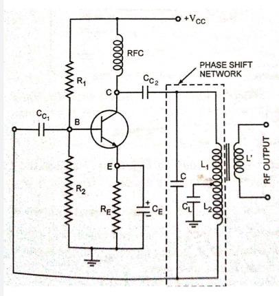
DIFFERNT TYPES OF LC OSCILLATORS AND THEIR WORKING1.TUNED COLLECTOR OSCILLATOR
Fig2tunedcollectoroscillator
Page
Oscillators can also be divided into groups based on the ingredients they include. They are RC oscillators and LC oscillators.ThecombinationofRCandLCoscillatorsaresaid tobetransistoroscillators. RC oscillators uses resistors and capacitors whereas LC oscillators uses inductors at capacitors as their phase shifting circuits. The examples of LC oscillator are tuned collectoroscillator,tunedbaseoscillator,Colpittsoscillator, Hartleyoscillator,clapposcillator,crystaloscillatoretc.
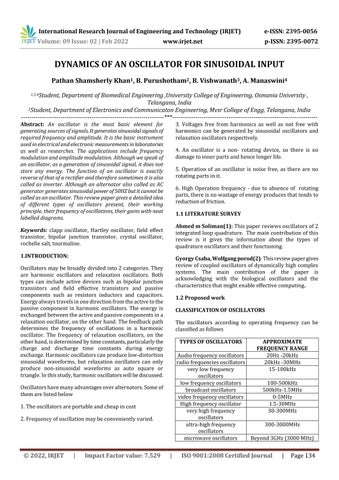
WORKING: whenthesupplyVCCisswitchedon,atransient holdoncurrentiscausedinthetunedLCcircuit.Itisdueto riseofcollectorcurrenttoitsquiescentvalue.Thistransient currentinitiatenaturaloscillationsinthetankcircuit.These naturaloscillationsinducesomevoltageintoL1bymutual inductionwhichcausessimultaneouschangeinbasecurrent. These variations in base current are amplified beta times andappearinthecollectorcircuit.Apartofthisamplified energy is used to meet the losses that occur in the tank circuit and the rest is radiated out in the form of electromagnetic waves. The turn ratio of L and L1 is determinedbythetotallosses.Higherisaturnratiolesseris thefeedbackvoltageappliedandviceversa.Thefrequency of oscillation that is the frequency at which bark Hausen criterionissatisfieddiffersfromtheresonantfrequencyof thetunedcircuit.Thereasonbehindthisistheloadingofthe transformersecondarytosomeextent. Thefrequencyofoscillationisgivenasf=1/2π√L√C. L=INDUCTANCEOFCOIL C=CAPACITANCE TUNED DRAIN OSCILLATOR
GENERAL FORM OF AN LC OSCILLATOR
Journal
Fig1LCoscillator
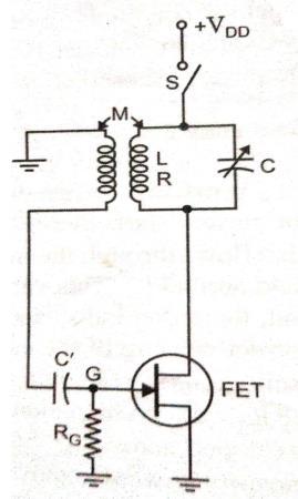
In the general form of an oscillator depicted in the above figure,anyoftheactivedevicessuchasvacuumtube,bipolar junctiontransistor,fieldeffecttransistororanoperational amplifiermaybeusedintheamplifiedsection,Z1,Z2,Z3,are the reactive elements constituting the feedback phase shifting circuit which resolve the frequency of oscillation. Here,Z1andZ2serveasanACvoltagedividercircuitforthe outputvoltageandfeedbacksignal.Thus,thevoltageacross Z2isthefeedbacksignal.Theequivalentcircuitisdrawnjust righttothefirstdiagramwiththefollowing2assumptions 1. hre of transistor is negligibly small and, therefore, the feedbacksourcehre.Voutisnegligible. 2.hreofthetransistorisverysmalli.e.,theoutputresistance hoeisverylargeand,therefore,1/hoeisomittedfromthe equivalentcircuit. ThegeneralformofanLCoscillatorisasfollows

WORKING WhenthecollectorsupplyvoltageVCCisturned on,thefirststepofworkbegins.ThecapacitorsC1andC2 are charged when the VCC is turned on. Oscillations are createdwhenthesecapacitorsC1andC2dischargethrough the Thecoil.oscillations
Fig4Franklinoscillator
Tuned Drain oscillator is similar to the tuned collector oscillator, discussed in above section, the basic circuit is given in above figure. Because of its high input resistance and high voltage gain a field effect transistor can be used insteadofabipolarjunctiontransistortomaketheoscillator circuit
The Franklin oscillator is shown in below figure. Here 2 commonemitteramplifierstagesareemployedtoprovide 360degreesphaseshiftfrominputtooutput.Thevaluesof thedifferentcomponentsusedinthecircuitarechosento provideoverallloopgainofthetwostagesslightlygreater thanunity.
FRANKLIN OSCILLATOR
Journal | Page136
Volume: 09 Issue: 02 | Feb 2022 www.irjet.net p ISSN: 2395 0072 © 2022, IRJET | Impact Factor value: 7.529 | ISO 9001:2008 Certified
The Colpitts oscillator is widely and commonly used commercialoscillatorwhichgeneratessinusoidalsignalsup to100MHz. ThebasicCircuitofthetransistorizedColpitts oscillatorisshowninthebelowfigure.Itconsistsofsingle stage inverting amplifier and LC phase shift network. The twoseriescapacitorsC1andC2formsthepotentialdivider circuitwhichprovidesfeedbackvoltage.Andthecapacitance developed across the capacitor C2 provide feedback requiredforsustainedsinusoidaloscillations.Theparallel combinationoftheemitterresistorsREandthecapacitorCE alongwithresistorsR1andresistorR2providesastabilized self bias.
The Hartley oscillator is just as popular as the Colpitts oscillator,andit'sutilisedasalocaloscillatorinalotofradio receivers.Thecircuitisdepictedinthediagrambelow.The HartleyoscillatorcircuitisidenticaltotheColpittsoscillator circuit, except that instead of two capacitors and one inductor,thephaseshiftnetworkconsistsoftwoinductors L1 and L2 and capacitor C. The amplifier's output is connectedtoinductorL1,andthevoltageacrossinductorL2 isusedtoproducethefeedbackvoltage.WhencoilL1and coil L2 are inductively connected, the result is an autotransformer.ThejunctionofL1andL2cannot,however, be immediately grounded due to the direct connection. Anothercapacitor,CL,isutilisedinstead.Thecircuitworks inasimilarway.
Fig5Colpittsoscillator HARTLEY OSCILLATOR
COLPITS OSCIALLATOR
International Research Journal of Engineering and Technology (IRJET) e ISSN: 2395 0056
Fig6Hartley'soscillator
across capacitorC2aretransferred tothe baseemitterjunctioninthecollectorcircuitandamplified. Commonly,theamplifiedoutputinthecollectorcircuitisof the exact same frequency as that of the oscillatory circuit. Theamplified output inthe collectorcircuitissupplied to the phase shifting circuit in order to overcome the losses. Thus, the phase shifting circuit is getting energy continuously from the collector circuit to overcome the losses occurring in it and, therefore ensures undamped oscillations.The energy supplied to theirtank circuit is of correctphasesatisfyingthebarkHausencriteria

International Research Journal of Engineering and Technology (IRJET) e ISSN: 2395 0056 Volume: 09 Issue: 02 | Feb 2022 www.irjet.net p ISSN: 2395 0072 © 2022, IRJET | Impact Factor value: 7.529 | ISO 9001:2008
4. J.B.Gupta, “Utilization of Electric Power and Electric Traction”S.K.Kataria&SonsPublications,2010.
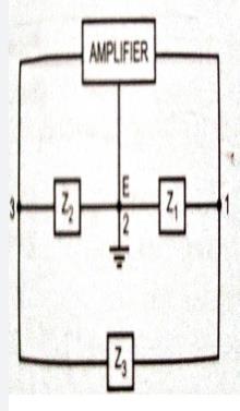
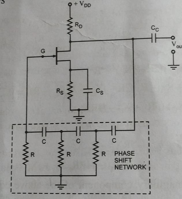
ARcphaseshiftoscillatorisextremelyeasytouse.Instead ofabipolarjunctiontransistoramplifier,thecircuitusesa common source field effect transistor amplifier, which is followed by a three section RC phase shift network. The amplifier stage is self biased using a capacitor bypassed source resistor Rs and a drain bias resistance Rd. This section'soutputissentbackintothegate.Ifthephaseshift network's loading on the amplifier is believed to be insignificant, the amplifier produces a 180 degree shift between the amplified output voltage Vout and the input voltageVinatgate.Anadditionalphaseshiftisproducedby thethree sectionrcphaseshiftnetwork,whichisafunction ofsomefrequencyofoperation,ffrequency=180degrees. The total phase shift from the gate around the circuit and back to the gate will be exactly 0 at this frequency. If the magnitudeofdictationappearstobelarge,thiswillbethe frequencyatwhichthecircuitwilloscillate.
5. Compared to other oscillators such as Wein bridge oscillators and Colpitts oscillators, the design of this Rc phase shift oscillator is particularly easy since it does not neednegativefeedbackorstabilisationmeasures.
DISADVANTAGES
PHASE SHIFT OSCILLATOR BENEFITS AND DISADVANTAGESAREDESCRIBEDBELOW.
1.Theoutputofthisnetworkisverysmallbecauseithave smallfeedbacknetworkemployedinit
1. Ramakanth A Gayakwad, Op Amps and Linear ICs, 4th Edition,PHI,EEEdition,2013.
ADVANTAGES
3.Becausetheoutputissinusoidal,thereisnodistortion.
CONCLUSION
PHASE SHIFT OSCILLATOR
6.Hughes,"ElectricalTechnology",VIIEdition,International Student on,AddisonWelseyLongmanInc.,1995
Certified Journal | Page137
4.Theseoscillatorsarecapableofworkingatbothlowand highfrequencies.
BIOGRAPHIES
2. When compared to other oscillators, the Rc phase shift oscillatorprovideshigherstability.
2.WhencomparedtoWeinbridgeoscillatorthefrequency stabilityisnotthatgood.
5. Abhijit Chakrabarti, Sudipta Nath, Chandan Kumar Chanda, “Basic Electrical Engineering” Tata McGraw Hill, Publications,2009
2. R.F Coughlin and F.F Driscoll, Op Amps and Linear IntegratedCircuits,PHI,EEEdition,4thEdition.2001.
Pathanshamsherlykhan Passionateaboutexploringworld andmakingitbetterthanthepast by means of advancements in technology.
Fig7phaseshiftoscillator
REFERENCES
3. JB Gupta, Electronic Devices and Circuits, S.K Kataria & sons,5thEdition,2012.
The working principles, operating frequencies, circuit diagramsofthesinusoidaloscillatorsareveryimportantin understanding any complex circuits found in devices. The proposed review gives acknowledgement of different sinusoidaloscillatorspresentandhelptheminperforming betterresearches.
1.Theystartwithlowfrequencyrangesandworktheirway up to high frequency ranges (from a few HZ to several hundredkHz)
3.Inordertodeveloplargefeedbackvoltageitneedsahigh voltagebatteryapproximatelyof12volts

International Research Journal of Engineering and Technology (IRJET) e ISSN: 2395 0056 Volume: 09 Issue: 02 | Feb 2022 www.irjet.net p ISSN: 2395 0072 © 2022, IRJET | Impact Factor value: 7.529 | ISO 9001:2008 Certified Journal | Page138 B AtPurushothammostinterests in gaining knowledgeandnewtechnologies, developingthenation B.Vishwanath A.Manaswini