1. INTRODUCTION
Abstract
1.1 PROBLEM STATEMENT
1School of Mechanical Engineering, MITWPU, Pune, India *** Tires have been modified on a regular basis since their discovery in order to improve their life and function in boosting automobile safety. . As we all know, that vehicle is an essential part of our life, because it helps us travel miles in a few minutes. The tires' air pressure needs to be maintained at an ideal level for better vehicle running and for the safety of the vehicle. SO this project was brought into account by keeping into consideration the fuel consumption, vehicular safety and comfort. This system regulates vehicle tire pressure, enhancing fuel efficiency and decreasing tire wear; as a result, tire life is extended and tire replacement time and expense are reduced. One of the key goals of implementing this system is to maintain appropriate tire pressure. The pressure gauge monitors the tire pressure and inflates it when it falls below the desired amount. This paper explains how the "Automatic tire inflation system" works, as well as its benefits and drawbacks, for researchers and new learners.
Anotherdecreased.benefit
Briefdescriptionoftheproblem
Key Words: Improved Life, Vehicular Safety, Air Pressure, Fuel Efficiency, Advantages and Limitations, Automatic Tire Inflation System.
Todesignandconstructanautomatedtireinflationsystem that inflates the tire when the pressure falls below the specifiedlevel.
International Research Journal of Engineering and Technology (IRJET) e ISSN: 2395 0056 Volume: 09 Issue: 02 | Feb 2022 www.irjet.net p ISSN: 2395 0072 © 2022, IRJET | Impact Factor value: 7.529 | ISO 9001:2008 Certified Journal | Page107
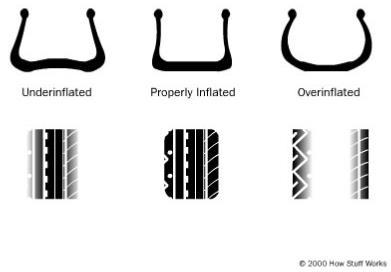
of incorporating this system is that it improvesvehiclehandlingandcontrol,loweringtheriskof accidents. Air is delivered to the rotor assembly through flexible ducting and a rotating bearing, which inflates the tire By maintaining ideal pressure in tires, braking and handlingworkattheirbest.Whenthissystemisinstalled, there will be no need for the driver or any passenger to check the pressure manually, thus reducing time and drudgery.
A. Below problems are common:
Fortunately, the automated tire inflation system greatly assistsintheresolutionoftheseproblems.Itadjustsforair lossinthetireonaregularbasis.Asaresult,bynotmanually checkingtirepressureonaregularbasis,thehumaneffortis
1.Increasedwear 2.Comfort 3.Handling 4.FuelEconomy
Tires are the second most costly component for transportationfirms.AccordingtotheAmericanAutomobile Association,80%ofcarshaveatleastoneunderinflatedtire amongtheothers.Accordingtotheirfindings,whenthetire pressure is less than two psi below the recommended pressure,fuelefficiencyisloweredby10%.[1] Inaddition, according to studies conducted by the NACFE in 2013, an incorrectlyinflated tirecausesa vehicletoconsumemore fuel than is necessary. [1]. The natural movement of air throughtheelasticrubbersoftiresalsolowersthepressure. When there is a decrease in 10 degrees Fahrenheit of the surrounding temperature, the one psi pressure of the tire decreases.Whentiresmakecontactwiththegrounddueto friction,heatisgenerated,whichmeltsthetire'srubber,and underinflatedtiresgetoverheatedeasily.Anunderinflated tireenginehastoworkharder,thustakingmorefueltorun thevehicle.Becauseclimaticconditionsdifferfromplaceto place,it'scriticaltomaintainpropertirepressuretoenhance fueleconomy.Petrolanddieselarenon renewableenergy sources,andmanynationsimportgasoline/oilfromDubai and Oman owing to their availability. Under typical atmosphericcircumstances,thereisamonthlyreductionof 0.5 to 1 psi tire pressure. The safety of the passengers, as wellasthevehicle'sfueleconomy,tirelife,andtireblowout reduction, are all important components of a vehicle
Pauras Ghag1
Automatic Tire Inflation System
1.Under inflatedtire 2.Maintainingwrongpressureinthetire B. Below parameters are affected:

battery[6].Asaresult,reachingthedesiredpressurelevelis asimpletask.Whencompressedairisnecessary,therotary jointis utilizedto rotateand deliver pressurizedairatthe sametime.
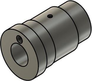
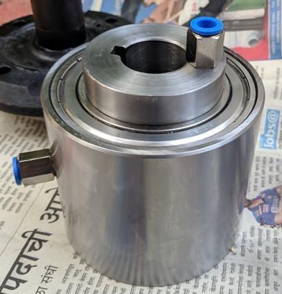
3.1 SPECIFIC DESIGN CRITERIA DESIGN OF ROTARY JOINT:
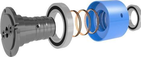
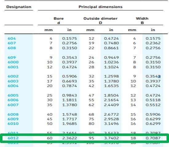
A] Arotaryjoint,alsoknownasarotaryunion,allowsfluid toflowintoandoutofspinningequipmentfromastationary supplypipe. B] Theprimarycomponentsofarotaryjointare: 1)Shaft 2)Bearings 3)Seals 4)Housing C] In our design, two ball bearings were used to reduce contactfrictionbetweenthetworotatingpartsandensure smoothoperationathigherRPMs.
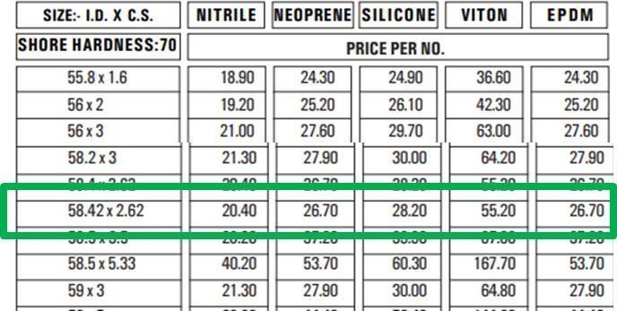
D] Topreventairleakage,dynamicpneumaticseals Orings areusedandbasedontherequirements,appropriateOring materialwasselected.Inourprototype,wehaveusedNitrile, but during actual implementation, Viton or PTFE can be used.
To have An Automatic System: When tires are under inflated,anautomatedsystemsavesbothhumanenergyand timebyreplenishingthemwithair. To improve fuel efficiency & tire life: Thissystemhelpsin lessconsumptionoffuelandimprovestirelife.
Thistechniqueworksbecausethecompressorsuppliesairto the tire while the car is moving. The compressed air is deliveredtotherotaryjoint,fromwhichitisdeliveredtothe tire,whichisunderinflated.Becauseoftherotationaljoint,air can be quickly delivered to the tire without tangles in the hoses [2] When the proper tire pressure is attained, an automatedsmallaircompressorshutsoffautomatically.The
1.2 OBJECTIVES AND SCOPE To maintain the required tire pressure: The system's purpose is to keep and regulate the pressure in all of the system's tires in response to changing loads and driving circumstances.
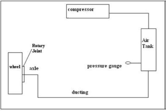
TheThepressurebelowtheThereoneaxletoisDuctingconnectedairsystem,compressorcompressestheairintheautomatedtireinflationasindicatedinfig.Atthedesiredpressure,ambientiscompressed.Theoutflowofthecompressorportistotheoppositeendoftherotaryjointbyducting.transportscompressedairtothejoint.Axlesupportprovidedbytwopedestalbearings.Nutsandboltsareusedattachthebearingstothestiffsupports[3].Ononeend,thespinsaroundtherimorwheel.Theaxleisconnectedtoendofthecouplerandtherotaryjointtotheother[4]areelectronicsensorsusedtodetecttirepressurewithhelpofapressuregauge.Whenthetirepressurefallstheappropriatelevel,thesensorsdetectthedropinandtransmitafeedbacksignaltothecompressor,airpressureinthetireismaintainedasaresultofthis.reciprocatingcompressorisdrivenbythevehicle's12V
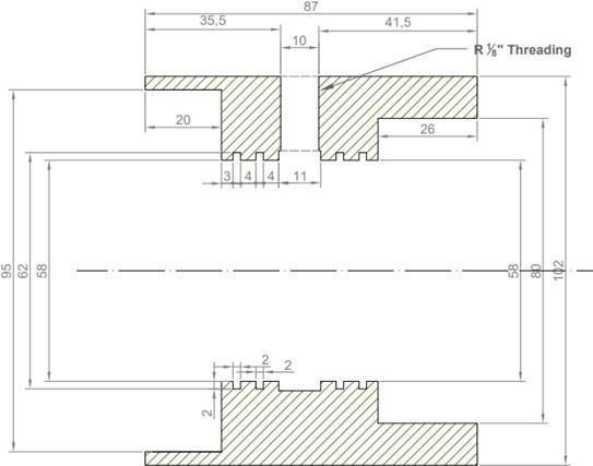
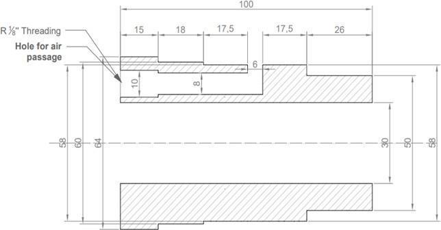
E] The rotary joint was designed according to the axle diameter, standard bearing dimensions and standard pneumaticsealsavailableinthemarket.
International Research Journal of Engineering and Technology (IRJET) e ISSN: 2395 0056 Volume: 09 Issue: 02 | Feb 2022 www.irjet.net p ISSN: 2395 0072 © 2022, IRJET | Impact Factor value: 7.529 | ISO 9001:2008 Certified Journal | Page108
3. WORKING PRINCIPLE
5.Frequentreplacementoftires
2. METHODOLOGY

International Research Journal of Engineering and Technology (IRJET) e ISSN: 2395 0056 Volume: 09 Issue: 02 | Feb 2022 www.irjet.net p ISSN: 2395 0072 © 2022, IRJET | Impact Factor value: 7.529 | ISO 9001:2008 Certified Journal | Page109
SELECTION OF O RING:
ROTARY JOINT
MostoftheOringmanufacturersrefusedtomanufacture8O ringsaccordingtoourdesignastheymanufacturedsealsin Hence,bulk.wehadtoselectastandardOringfromthesupplier's catalogue.
SELECTION OF BEARINGS:
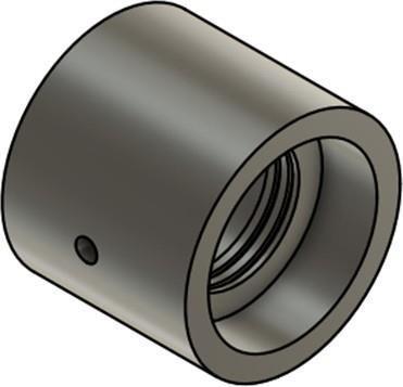
CAD MODEL OF ROTARY JOINT: Becausethein motiontireinflatorwasdesignedforusebya localpassengercar,themainstumblingblockistheexistence ofanaxleshaftthatrunsstraightthroughthecenterofthe wheel,necessitatingtheneedofaseparatesystemtochannel airtothetire Arotaryjointwithonehalfrotatingwiththe driving axle hub and the other half stationary with the spindle is used to alleviate this problem. Air will be transported from the stationary joint to the spinning joint throughanairchamber.

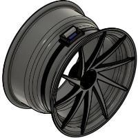
SENSOR INSTALLATION
3.2 PROPOSED SOLUTIONS
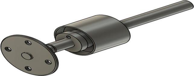
International Research Journal of Engineering and Technology (IRJET) e ISSN: 2395 0056 Volume: 09 Issue: 02 | Feb 2022 www.irjet.net p ISSN: 2395 0072 © 2022, IRJET | Impact Factor value: 7.529 | ISO 9001:2008 Certified Journal | Page110 Sectional View and CAD of Outer and Inner Part of Rotary Joint ASSEMBLY OF ROTARY JOINT: CAD AND ACTUAL MODEL OF ASSEMBLY
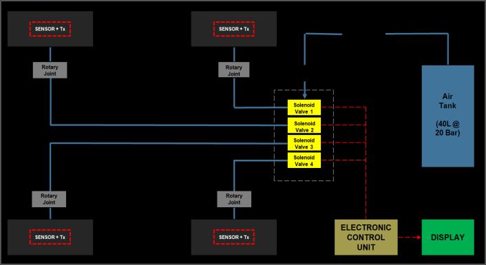
The suggested system, which is primarily split into three elements,isdepictedintheblockdiagrambelow:
Rotary ElectronicJointControlUnit PneumaticControlUnit
3.2.1 TIRE PRESSURE MANAGEMENT
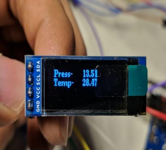
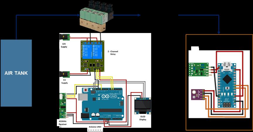
TheArduinoNano,a433MHztransmitter,anda4000mAh batteryareusedintheproposedsystem.Tireinflationcanbe avoidedbyavoidingextremesintemperatureandpressure [10]. The prior system's temperature and pressure limitations have also been extended, with temperatures ranging from 40 to 125 degrees Celsius and pressures rangingfrom0to750kilogramspersquaremeter.Thelow power TPMS is built using sensors, radio communication (RF),andaSoCunit.[11] The sensor, along with Arduino Nano, battery and transmitter,isassembledandwiredtogetherandarekeptin asmallbox.Theboxisheldinsidethewheelwiththehelpof asteelband.Thefollowingfiguresshowtheinnersideofthe casing,whichprotectsthebattery,ArduinoNano,andwiring.
[7]Prof.Miss.ShingaviArchanaAshoklal1Mr.BachkarArvind Nanasaheb2Mr.DomadeAnandaChindhu3Mr.PoteSuyog Kantaram4Mr.SomwanshiSachinVitthal5.“AirFillingin Moving Tire” IJSRD. IJSRD International Journal for ScientificResearch&Development|Vol.4,Issue01,2016| ISSN(online):2321 0613
[11] A. Vasantharaj1, K. Krishnamoorthy2. “Tire Pressure Monitoring System Using SoC and Low Power Design”. Circuits and Systems, 2016, 7, 4085 4097 http://www.scirp.org/journal/csISSNOnline:2153 1293 ISSNPrint:2153 1285
[1]KrishnaKumarKarothiyaManojKumar.“Designsystemof anautomatictirepressureinflationanddeflationsystem”. International Journal for Research in Engineering Application & Management (IJREAM) ISSN : 2454 9150 Vol 06,Issue 08,NOV2020. [2] Ashish Shinde1 Vishad Patil2 Ashish Mane3 Shubham Pawar4Prof.AniketDeshmukh5.“AutomaticTireInflation Systems A Review”. IJSRD International Journal for ScientificResearch&Development|Vol.6,Issue02,2018| ISSN(online):2321 0613.
[5]1PrabhakarN2PranilSakinal3VaradTamhankar 4Rutika Sakore.“RATIS(RapidAutomaticTireInflationSystem)”. IOSR Journal of Engineering (IOSRJEN) www.iosrjen.org ISSN(e):2250 3021,ISSN(p):2278 8719SpecialIssue|| September 2021|| PP 01 15 7th National Conference On Advancements in Communication, Computing and ElectronicsTechnology ACCET2021.
In conclusion, the in motion tire inflator system can be realizedusingtherotaryjointairtransfermethod.Alotof research and modification can be done before the system goes to perfection. As a novel product in the automotive supply industry, the in motion tire inflator system has a goodchanceofsucceeding.Asmentionedearlier,themajor advantage of this implementation in technology that will allowfortirepressuretobefitfordrivingconditionswillbe theownerofthevehicles. Theywillexperienceareductionintirewearaswellasan increase in fuel economy and efficiency, resulting in long term cost benefits despite the initial investment in the technology[3] REFERENCES
[10]Balaji,K.,Madhav,B.T.P.,SyamSundar, P.andRakesh Kumar, P. (2011) “Tire Pressure Monitoring and Communicating Antenna in the Vehicular Systems”. International Journal of Advances in Engineering & Technology,1,422 428.
[3] 1Prof. P.M. Borade, 2Gopinath Keskar, 3Yash Girme, 4Digambar Ghevade, 5Akshay Shelke. “CENTRAL TIRE INFLATIONSYSTEM”.ISSN:2455 2631©June2017IJSDR |Volume2,Issue6.
[6]1ApuravHinge2PuspendraUpadhyay.“AREVIEW STUDY ON SELF INFLATED TIRE SYSTEM”. NOVATEUR PUBLICATIONS International Journal of Innovations in Engineering Research and Technology [IJIERT], ISSN: 2394 3696 Conference Proceedings of i Mechanical EngineeringStudents Conference2018(i MESCON18) 28thDecember,2018
Journal
International Research Journal of Engineering and Technology (IRJET) e ISSN: 2395 0056 Volume: 09 Issue: 02 | Feb 2022 www.irjet.net p ISSN: 2395 0072 © 2022, IRJET | Impact Factor value: 7.529 | ISO 9001:2008 Certified |
4. CONCLUSIONS
Page111 3.2.2 ACTUAL SYSTEM Transmitter Circuit Receiver Circuit
[4]HarshalJunankar1VishnusagarBihare2NishantGiradkar3 Chetal Gupta4. “A Review: Automatic Tire Inflanation System”. IJSRD International Journal for Scientific Research & Development| Vol. 3, Issue 01, 2015 | ISSN (online):2321 0613