International Research Journal of Engineering and Technology (IRJET) e ISSN: 2395 0056 Volume: 09 Issue: 02 | Feb 2022 www.irjet.net p ISSN: 2395 0072 © 2021, IRJET | Impact Factor value: 7.529 | ISO 9001:2008 Certified Journal | Page1019 A Comparative Study on Enhancing the Factor of Safety for Retaining Walls Against Failure by the Use of Reinforcement Strips with Soil Mass Md. Abdullah Al Arafat1 , Md. Manir Mia2

INTRODUCTION
The application of the reinforcing elements technology in soil mass improves safety with a very cost effective and reliable method. In this research, we used the analytical method of limit equilibrium to check the total internal and exterior stability performance of retaining walls with seven alternative height models by numerical calculation. The major goal of this study is to compare the factor of safety against failure (pullout, strip breaking, bearing capacity, overturning, sliding, etc.) in reinforced and unreinforced models derived by using numerical analysis, to validate the most realistic. The results from the parametric and comparative studies have provided us with a lot of knowledge about the internal and external stability of reinforced earth retaining walls. In this study, galvanized steel strips are engaged as metallic components in the reinforced soil. Here, we investigate serviceability through internal stability to boost the wall's service life and factor of safety against overturning, sliding, and bearing capacity failure.
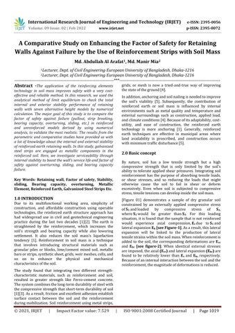
2.0 Basic concept By nature, soil has a low tensile strength but a high compressive strength that is only limited by the soil's ability to tolerate applied shear pressures. Integrating soil reinforcement has the purpose of absorbing tensile loads, or shear stresses, and so reducing the loads that might otherwise cause the soil to fail in shear or deform excessively. Even when soil is subjected to compressive stress,tensiletensionscandevelopinsidethesoilmass. [Figure 01] demonstrates a sample of dry granular soil constrained by an externally applied compressive stress of S3 andloaded by compressive stress of S1, where S1 would be greater than S3. For this loading situation,itisfoundthatthesamplethatisnotreinforced would experience axial compression, Ev due to S1 and lateralexpansion Eh [see Figure 1].Asaresult,thislateral expansion will be linked to the production of lateral tensilestrainswithinthesoilmass.Whenreinforcementis added to the soil, the corresponding deformations are Evr and Ehr [see figure 2]. When identical external stresses areimposed,theaxial (Evr) andlateralexpansion (Ehr) are found to be relatively lower than Ev and Eh, respectively. Becauseofaninternalinteractionbetweenthesoilandthe reinforcement,themagnitudeofdeformationsisreduced.
Due to its multifunctional working area, simplicity of construction, and affordable construction using operable technologies, the reinforced earth structure approach has had widespread use in civil and geotechnical engineering practice during the last two decades [1][2]. The earth is straightened by the reinforcement, which increases the soil's strength and bearing capacity while also lowering settlement. It also reduces the soil mass's liquefaction tendency [1]. Reinforcement in soil mass is a technique that involves introducing structural materials such as granular piles or blocks, lime/cement mixed soil, metallic barsorstrips,syntheticsheet,grids,weirmeshes,cells,and so on to enhance the physical and mechanical characteristicsofthesoil.
2Lecturer, Dept. of Civil Engineering, European University of Bangladesh, Dhaka 1216 ***
Abstract
Key Words: Retaining wall, Factor of safety, Stability, sliding, Bearing capacity, overturning, Metallic Element, Reinforced Earth, Galvanized Steel Strips Etc. 1.0
Inaddition,anchoringandsoilnailingisneededtoimprove the soil's viability [5]. Subsequently, the contribution of reinforced earth or soil mass is influenced by internal environments such as metal quality and temperature and external surroundings such as construction, applied load, andclimateconditions[4].Becauseofitsadaptability,cost utility, and ease of construction, the reinforced earth technology is more anchoring [1]. Generally, reinforced earth techniques are effective in municipal areas where land availability is proscribed, and construction occurs withminimumtrafficdisturbance[5].
1Lecturer, Dept. of Civil Engineering, European University of Bangladesh, Dhaka 1216
The study found that integrating two different strength characteristic materials, such as reinforcement and soil, resulted in greater strength like Ferro cement concrete. Thesystemcombinesthelong termdurabilityofsteelwith thecompressivestrengththatshort termdurabilityofsoil [1][3].Asaresult,frictionandexcellentadhesionestablish surface contact between the soil and the reinforcement during mobilization. Soil reinforcement using metal strips, grids, or mesh is now a tried and true way of improving thestateoftheground[4].
b=BreadthoftheStrips t=ThicknessoftheStrips tactual=tdesign +r(rateofcorrosion) Metallicstrip ZX ZY
Figure 1:Unreinforcedsoilsample S1 Evr S3 S3 S1 Evr Figure 2:Reinforcedsoilsample (Evr< Ev and Ehr<Eh)
SizeoftheStructure


Selectmetallicelements, suchas throughCheckstripsreinforcementorties.serviceabilityinternalstability(dependingontherateof
FS (overturning) = 3, FS (sliding) = 3, and FS (bearing capacity failure) = 3 to 5 are recommendedasminimumvalues.

International Research Journal of Engineering and Technology (IRJET) e ISSN: 2395 0056 Volume: 09 Issue: 02 | Feb 2022 www.irjet.net p ISSN: 2395 0072 © 2021, IRJET | Impact Factor value: 7.529 | ISO 9001:2008 Certified Journal | Page1020 S1 Ev S3 S3 S1 Eh
corrosion). ExternalStability (BearingCapacity, SlidingandOverturning)
The width of (b) these strips islarger than their thickness (t), making them flexible and linear (Usually, the range within t<20 40mm and b= 6 80 mm. The typical rate of corrosion of galvanized steel strips, according to Banquet and Lee (1975), is between 0.025 and 0.050 mm/yr. As a result, the rate of corrosion must be included into the reinforcingdesign.
2.1 Work Flow Diagram 3.0 Metallic Strips Size
Reinforced case: (Figure-1) Ifthesoilisreinforced,extra confiningstress ΔS3 is createdbytheinteractionbetween the soil and the reinforcement. So a larger value of S1 is needed to cause destruction This is due to the fact that increments of S1 generate increments of S3, which results in relatively low increases in the applied shear stress, which is relatively half of the S1 and [S3+ ΔS3]. So, ΔS3 playsacrucialroleinthiscase.Itcausesincreasedservice lifeofthestructuresagainstfailure.
The major of the reinforcement strips are usually metal and made of galvanized steel. To enhance the friction between the metal and the soil mass, these strips are simpleorincludemanyprotrusions,suchasribsorgloves.
Unreinforced case: When applied shear stress reaches the soil's shear strength, general shear failure of the unreinforcedsoiloccurs. (Figure 1) Incontinuationwhen anunreinforcedsoilisconstrainedbyaconstantstress S3 and the magnitude of S1 is gradually raised, the soil is subjected to a steadily rising shear stress, which is nearly halfofdifferencebetween S1 and S3
Generallythebreadthisequaltoorgreaterthantwotimes ofthethickness.
qult=CNc +0.5(Ƴ2LN Ƴ)
Ƴ1=unitweightofbackfillmaterial(Granular) Nc,NƳ=Meyerhof’sbearingcapacityfactor correspondtothefoundationsoilfrictionangle =frictionangleofin situsoil(Foundation) S′ =effectiveverticalstressatadepth of“H”.
qult=Ultimatebearingcapacityoffoundationsoil. C=Cohesion Ssur=stressduetosurcharge Ƴ2=unitweightofin situsoil(Foundation)
Generalbearingcapacityequation(Meyerhof’s)
c. As a result, the aspect of safety(FSp) against strip pulloutwouldbeobtained FSp= d. Subsequently, the full strip of length can be found here by the following equation, which is equal to the effective length (Le) plus the length (Lran) within the Rankinfailurezone.Where,Effectivelength, Le and Thelength(Lran)withintheRankinfailurezone, Lran ( ) Where, =frictionalangleofgranularbackfillsoil =effectiveverticalpressureatadepthof“d”. andH=Heightoftheretainingwall.
Internal StabilityInternal stability is mainly subjected to the height of the wall, the characteristics of the soil mass with frictional angle, soil reinforcement interaction, and the size of metallicstrips.
4.0 Numerical Analysis
a. b. Factor of safety against overturning The check for overturning can be done by using the followingequation: FS(overturning)= The overturning moment is determined as the moment established by the horizontal loads in relationtothebase'smost bottom leftcorner. Overturning moment MO=FaX X=armdistance = [Surcharge] = [Non surcharge] Foranyhorizontalload,theleverarmdistancewillbe. When a non surcharge load is present, one third of the wall height from the bottom of the base to the surface level is employed. When a surcharge load is present,one halfofthewallheightfromthebottomof thebasetothesurfacelevelisused.
4.1 Design Procedure
FS(bearing)= Withsurcharge= Ƴ1H+Ssur Withoutsurcharge =Ƴ1H[relatedtototalheight,H]
International Research Journal of Engineering and Technology (IRJET) e ISSN: 2395 0056 Volume: 09 Issue: 02 | Feb 2022 www.irjet.net p ISSN: 2395 0072 © 2021, IRJET | Impact Factor value: 7.529 | ISO 9001:2008 Certified Journal | Page1021
a. Factor of safety in case of a bearing failure
b. Thefactorofsafetyagainststripbreaking(FSb)2.5to3 isgenerallyrecommendedforstripsatalllayers FSb Where,=widthofeachstrip. =thicknessofeachStrip. fy=yieldstrengthofthereinforcementstrip. Here, the thickness of the strip can be determined by the(a)and(b)equations. tactual=tdesign +r(rateofcorrosion) Consequently, the maximum frictional force (Ff) for a stripwouldbeobtainedatadepthof"d”anditis Ff Where=, =frictional angle between soil and reinforcement stripinteraction. d=atthatdistances,wherethestripsareplacedatfull depth.
a. Reinforcement strip force (Q) per unit length of the retainingwall. Q=Sa ZxZy Where,Q=stripsbreakoutforce. Sa=activeearthpressureofsoilmass Zx=lateralspacingofstrips. Zy=verticalspacingofstrips.
4.2 External Stability External stability is mainly subjected to the height of the wall, the characteristics of the foundation soil layer with ultimatebearing capacity, effectivestressofthesoilmass, andthelengthofmetallicstrips.
Fa=Activeforce = γ1 KaH2 Resisting moment Mr = PnZn =Areaofanactiveloadingzone Z=
International Research Journal of Engineering and Technology (IRJET) e ISSN: 2395 0056 Volume: 09 Issue: 02 | Feb 2022 www.irjet.net p ISSN: 2395 0072 © 2021, IRJET | Impact Factor value: 7.529 | ISO 9001:2008 Certified Journal | Page1022 c. Factor of safety against sliding The following equation can be used to check for FSsliding: (sliding) = [k=2/3) 4.3 Wall properties Propertiesofthegranularbackfill: ϕ′0=350 γ1 =17kN/m3 Propertiesofin situ(Foundation)soil: =260 Ƴ2=16.5KN/m3 C=30KN/m2 Galvanizingsteelreinforcement: Widthofthestrip,b=60mm Zx =0.6m center to center Zy =1.0m center to center Steel Strength Properties for elements with nominal thickness t ≤ 40 mm EN10025-2 Hot rolled products -Non-alloy structural steels S235 ƒy=235000KN/m2 =220 Nc=22.25 NƳ= Required12.54FS(b) =3, RequiredFS(p)=3 Table 1: Factorofsafetyagainstfailureinbreaking, bearing,overturningandsliding wall(m)Heightofthe FS(break ing) FS(bear ing capacity) FS(Overtu rning) FS(Slid ing) Comment 5 3.07 23.76 64 7.95 Safe 7.5 2.50 16.66 33.42 5.75 Safe 10 2.50 13.10 21.80 4.64 Safe 15 2.250 9.95 14.285 3.75 Only unsafe for breakingstrip 20 2.150 8.075 10 3.15 Only unsafe for breakingstrip 30 1.945 6.59 7.72 2.76 Not andbreakingagainstsafesliding 40 1.919 5.86 6.68 2.57 Not andbreakingagainstsafesliding =safe =notsafe Chart 1:FS(breaking)vsWallheight Chart 2:FS(bearing capacity)vsWallheight(m) Chart 3: FS(overturning) vs Wall height(m) 0 0.5 1 1.5 2 2.5 3 3.5 5 7.5 10 15 20 30 40 againstsafetyofFactor breaking Wall height(m) FS(breaking) vs wall height(m) safe not safe 5 7.5 10 15 20 30 40 0 5 10 15 20 25 5 7.5 10 15 20 30 40againstsafetyofFactor capacitybearing Wall height(m) FS(bearing capacity) vs wall height(m) safe 0 10 20 30 40 50 60 70 5 7.5 10 15 20 30 40 againstsafetyofFactor overturning Wall height(m) FS(overturning) vs Wall height(m) safe
International Research Journal of Engineering and Technology (IRJET) e ISSN: 2395 0056 Volume: 09 Issue: 02 | Feb 2022 www.irjet.net p ISSN: 2395 0072 © 2021, IRJET | Impact Factor value: 7.529 | ISO 9001:2008 Certified Journal | Page1023 Chart 4:FS(sliding)vsWallheight(m)
2. To check the external stability of these walls, the factorsofsafetyagainstbearingcapacity,overturning, and sliding are considerably higher than the recommended value of 3 to 5. But on the other hand, onlythe30mand40mwallsfailedinsliding.Here,the height of the wall is significantly responsible for this predicament. But for all this, reinforcement strips should be used according to design, and the backfill soilmustbegranular.Hence,sufficientreinforcement lengths lead to a stable retaining wall, and on the contrary, excessive reinforcement amounts reduce economicefficiency.
5. CONCLUSIONS
REFERENCES
1. In the numerical analysis, different wall heights, i.e., 5,7.5, 10, 15, 20, 30, and 40 m, are used in the investigation. To check the serviceability of these walls at the same properties at different heights, we foundthefactorofsafetyagainststripbreakingissafe for 5,7.5, and 10 m walls, but other walls are not safe because of their safety value against strip breaking is below 2.5. So, the width and thickness of the strips have to be increased to keep the other walls safe. Therefore, here we have to look at the financial matter. Therefore, it is important to make sure that thereinforcementsweusetoextendtheservicelifeof thewallareadequate.
BIOGRAPHIES
2) I. P. Damians; R. J. Bathurst; A. Josa; and A. Lloret“Numerical Analysis of an Instrumented Steel Reinforced Soil Wall” International Journal of Geomechanics Volume 15 Issue 1 February 2015(ASCE).
1) Vijay Kumar, Dr. Bharat Nagar, “Analysis and Design of Reinforced Earth wall,” Science (IJSER) Volume 12, Issue 4, April 2021 Civil Engineering DepartmentofJagannathUniversityJaipur,India.


3) Mauricio Ehrlich, Member, ASCE; and James K. Mitchell, Fellow, ASCE "Working Stress Design Method for Reinforced Soil Walls" Journal of Geotechnical Engineering / Volume 120 Issue 4 April1994. 4) IMADA.BASHEERANDYACOUBM.NAJJAR “Reliability Based Design of Reinforced Earth RetainingWalls"TransportationResearchRecord Journal of the Transportation Research Board · January1996
fetofFactorsayagainst idsling Wall
FS(Sliding) vs Wall height(m) safe
5) Shin, E. C.; Cho, S. D.; Lee, K. W “Case Study of Reinforced Earth Wall Failure during Extreme Rainfall” Proceeding of TC302 Symposium Osaka 2011: International Symposium on Backwards Problem in Geotechnical Engineering and MonitoringofGeo Construction 6) Meyerhof’s bearing capacity factor table for generalbearingcapacity. 7) Meyerhof’s bearing pressure distribution equation. 8) Active Earth pressure is calculated by coulomb equation. Dept.Lecturer,ofCivilEngineering EuropeanUniversityof Dept.Lecturer,DhakaBangladesh,1216ofCivilEngineering, EuropeanUniversityof DhakaBangladesh,1216 2 4 6 8 10 5 7.5 10 15 20 30 40 height(m) not safe 7.5 10 15 20 30 40
0
Inthisstudy,weinvestigatedthebehavioroftheretaining wall when the soil mass is reinforced by metallic strips andalsoanalyzedthefactorsofsafetyagainstfailure,such as strip breakout, bearing capacity, overturning, and sliding.Itisobservedthatthefactorofsafetyagainstthese failures is surprisingly improved, not only that it also increases the service life of the retaining wall. Here we investigated,fromsmalltolarge,sevendifferentheightsof the wall. The factor of safety against strip breaking (FSb) of 2.5 to 3, overturning of 3, sliding of 3, and bearing capacityof3to5isrecommendedasminimumvaluesfor unreinforced soil. As can be seen, when galvanized steel strips are employed as metallic components in the soil mass,frictionandefficientadhesionareestablishedbythe interaction between the soil and the reinforcement. As a result, axial and lateral expansion occurred at relatively lowerthanunreinforcedsoil.
5
