
1. INTRODUCTION
Compared with original 2WD vehicle that drives front wheelsorrearwheelssolelyAWDsystemcontainsarollto distributeenginedrivetotorsiontoeachfrontshaftandrear shaft. Sometimes AWD system was equipped with cross country vehicle that runs on rough road. Hardware configurationthatishandledduringthispaperdiffersfrom centerdifferential4WDandselective4WDasaresultofit distributes same power to any or all four wheels equally rangingfromCVTthefacilityistransferredtoprimaryshaft of2stagegearboxthentotheintermediateshaftwherevera cogwheel try transfers it to front differential and for rear wheelsthefacilityistransferredbyoutputshaft.
First Author: Mr. Swapnil Anil Kumavat, Graduate Student, Mechanical Engineering, SNJB’s Late Sau. Kantabai Bhavarlalji Jain College Of Engineering, Chandwad, Nashik,Maharashtra, India
AWD system is often used for each of longitudinal and lateraldrivingsafety.Duringthisregardit'svitaltosearch outthecurrentvehiclestatealsoasroadstate.asanexample, vehicleclimbshighslopehill,escapesfromlowletterofthe alphabetsurfaceandhaslateralmovementlikedoublelane modificationorcircularmotionwithhighrate.Andanalysis concerningmodelprognosticativemanagementoughttobe donetogetherwiththesenumerousdrivingthings.Thenit's expected that vehicle performances like driver’s riding qualityandsteadystatecorneringareimproved.
International Research Journal of Engineering and Technology (IRJET) e ISSN: 2395 0056 p ISSN: 2395 0072Volume: 09 Issue: 02 | Feb 2022 www.irjet.net © 2022, IRJET | Impact Factor value: 7.529 | ISO 9001:2008 Certified Journal | Page1013

Design and Analysis of All Wheel Drive Gearbox
Author: Mr. Swapnil Anil Kumavat Mr. Shreyas Rajendra Kshirsagar Co- Author: Mr. Darshan Pratap Jat Mr. Shubham Uddhav Sutar
Second Author: Mr. Shreyas Rajendra Kshirsagar Final Year Student, Mechanical Engineering, Sandip Institue of Technology and Research Center (SITRC), Nashik, Maharashtra, India
Forth Author: Mr. Shubham Uddham Sutar, Graduate Student, Mechanical Engineering, MET Institue of Engineering, Bhujbal Knowledge City, Nashik, Maharashtra, India ***
Third Author: Mr. Darshan Pratap Jat, Graduate Student, Mechanical Engineering, MET Institue of Engineering, Bhujbal Knowledge City, Nashik, Maharashtra, India
Abstract - The main purpose of this paper is to provide a gearbox with low reduction ratio, low weight and efficient for engine up to 500cc. It should also be used in All Terrain Vehicles demonstrated in international SAE BAJA. Engine power is transmitted via a hollow shaft in the gearbox to the intermediate differential, which has the task of distributing driving force equally to the front and rear wheels and of compensating for the difference in speed when cornering. The power is transmitted on the one hand from the intermediate differential to the rear axle differential via the propeller shaft and on the other hand, via a drive shaft to the front axle differential. The Assignment starts with the study of gearbox, theoretical calculations, and model designing on CATIA V5R20, analysis on ANSYS Workbench 14.5, verification, assembly, modification and at last final testing of gearbox.
Key Words: SAE BAJA, Reduction Gearbox, spur gears, Designing, Analysis.
Table 2: EngineRpmvs.GearboxRpm Enginerpm ratioCVT Gearbox inputrpm Gearoutputboxrpm Speed Traction 1900 3 519 43.25 4.76 1939.06 2000 2.5 664 55.33 6.08 1615.89 2200 2.2 830 69.16 7.5 1412.98 2400 2 984 82 9 1292.71 2600 1.8 1184 98.66 10.83 1163.44 2800 1.5 1530 127.5 14.00 969.53 3000 1.4 1757 146.41 16.09 904.89 3200 1.3 2018 168.16 18.50 840.26 3500 1 2827 239.16 26.31 646.3 3700 0.65 4667 398.91 42.80 434.52 3750 0.50 6150 512.5 56.41 387.81
International Research Journal of Engineering and Technology (IRJET) e ISSN: 2395 0056 p ISSN: 2395 0072Volume: 09 Issue: 02 | Feb 2022 www.irjet.net
Many kind of transmission like manual, sequential, automatic,directdrive,CVTbelt,CVTgear,ratherthanthis two kind of transmission that square measure highly regardedamongtheBAJAgroupssquare measuremanual transmission and CVT belt transmission. Manual transmission ordinarily called case is simply put in and pairedtoengine.However,thedisadvantagesofmanualcase squaremeasuretheridecomfort.Themotiveforcecomfort iscompromiseandfatiguetoextendthecomfortabilityof themotiveforce that willsendsup in increase the vehicle performance,itissuggestedtouseCVTwhichcannotsolely offer the infinite gear quantitative relation however conjointlyfacilitateinreducingtheloadanddriverfatigue. © 2022, IRJET | Impact Factor value: 7.529 | ISO 9001:2008 Certified Journal | Page1014
5. CONTINOUS VARIABLE TRANSMISSION 6. TRANSMISSION
Table- 1: CVTSpecification TypeofCVT GagedCVT CVTBelt CoggedTeethBelt MaximumCVTRatio 3:1 MinimumCVTRatio 0.43:1
3. DESIGN METHODOLOGY
2. OBJECTIVE AWDisoptimizedforon roadandoff roaduse.It’sthe aptitudetosendtheengine'spowertoanyorallfourtiresall ofthetime.It’llfacilitatekeepyourvehiclemovingforward higherthanfront wheeldriveorrear wheeldriveonsnow cladorrain slickedroads.Allvehiclesusedifferentials.These areaunitunitswithgears,connectedtotheoutputshaftsthat flipthewheels,thatletthewheelsflipatcompletelydifferent speeds.
4. ENGINE SPECIFICATIONS
The cool engine used on the vehicle is also a 4stroke, (305cc) displacement Briggs & Stratton engine of “Over HeadValve”kind(OHV).ItequippedtoteamsbyBriggsand Strattonatsponsoredvalueandistoremainstockasper theRulebook.Ithasa.75”key waydeviceshaftasoutput andacompressionrelationof8.0to1.Theengineweighs roughlysixtyfourlbs.Engineidlerevolutionsperminuteis on the point of 1750 revolutions per minute. At competition, the governor typically set at soap 3800 revolutionsperminutebelowitsrevolutionsperminute capabilities.TheCVTplaysamostimportantpartintheperformance ofthevehicleastherewillbenoclutchtopress,nolever to changing the gear ratio. Thus it not only saves the weight and driver fatigue but also provide smooth ride and saving time in acceleration. This is due to the capability of CVT by change the diameter by rotational force. CVT is the pulley system where the pulley can changesizetoachievetheoutputpower.Thisisallreason touseaCVTforfastaccelerationandeasyoptimizationof enginepower.
1. Searchingforallnecessaryparametersneeded forengine&gearcasepicks. 2. Calculationofneededpoweroutputfromgiven data. 3. Comparison&choiceofcorrectgearcase Inpreviouscars,themotiveforcefacetkillswitchwas placedtotheproperfacetontheSIM.Completelydifferent methodology for determination condition is often supportedthequalityofdownside.Wetendtofirstofall studythemosttorsionprovidedbytheengine,lossesat theCVT,reductionrevolutionsperminuteingearcaseand mosttorsionaccessibleatthetipofthegearcaseassembly andoutputshaft.Conjointlycalculatethefrictioneffort, drag force needed to drive the vehicle at varied speed. Choice of fabric is administrated by finding out varied material property and composition. The Geometrical model is formed by exploitation the CATIA. Conjointly Static and Thermal analysis is administrated by exploitationtheANSYSWorkbench14.5.
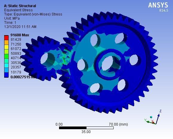
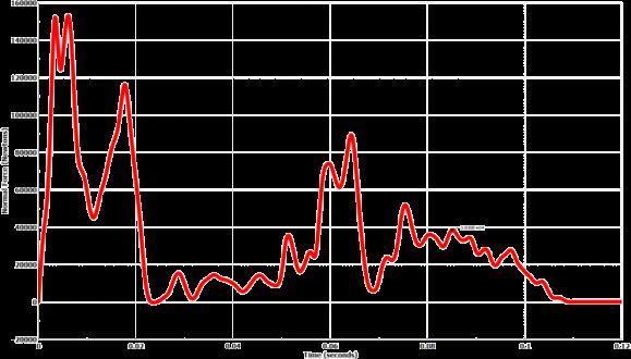
International Research Journal of Engineering and Technology (IRJET) e ISSN: 2395 0056 p ISSN: 2395 0072Volume: 09 Issue: 02 | Feb 2022 www.irjet.net Fig 1: TopViewofGearAssembly 6.1 Transmission Specifications GagedCVTiscoupledwithself designedgearbox. TopSpeed 58.4kmph GearRatio:1)Gearbox 6:1 2)CVT 3.9:1to0.9:1 Acceleration 3.32m/sec² AccelerationTime 4.88 sec Gradability 84.9% TorqueRequiredtocrossMudPit 549.98N m TorqueRequiredtohillclimb 520.94N m Fig- 2: IsometricViewofGearAssembly Analysisisdonetofindoutdifferentparametersofdesigned componentswhenactualloadingconditionsareappliedon them, which gives brief idea about stresses, FOS, Deformation, and velocity of the designed components. Followingimagesshowdifferentanalysiswhichincludesfirst gearpair,bevelgearpair.Inaddition,thereisdynamicfluid flow analysis on the casing and static analysis on intermediateshaft. Boundary Condition: Rigid wall with a mass equal to vehicle (240 Kg) launched at 60 kmph on the side of the vehicle with termination time of 100 millisecond and meshingsizeof5mm. Fig 3: FirstGearPair Chart 1: NormalForcevs.Timeforfrontimpact © 2022, IRJET | Impact Factor value: 7.529 | ISO 9001:2008 Certified Journal | Page1015 7. FINITE ELEMENT ANALYSIS 7.1 First Gear Pair

Calculations: Fig 4: BevelGearPair
Table 3: AnalyticalParametersofFirstgearpair Parameters Values Material 20MnCr5 MeshSize 5mm MeshType 2DTriangular Deformation 1.4mm
Table 4: AnalyticalParametersofBevelGearPair Parameters Values Material 20MnCr5 MeshSize 5mm MeshType 2DTriangular Deformation 1.2mm
Boundary Condition: The gear box is designed for the speedof60kmph.Beforeapplyingtheloadaresettospecify theconstraints.Thecenterportionofspurgearwherethe shaftisattachedsetasfixed.Theforceappliesononetooth atthepointofcontactoftwogears.Theappliedforceisfor 751RPM. The forcesacting onthegear are divided into 3 typesnamelytangential,radialandaxial.
International Research Journal of Engineering and Technology (IRJET) e ISSN: 2395 0056 p ISSN: 2395 0072Volume: 09 Issue: 02 | Feb 2022 www.irjet.net
Calculations: Force=OutputRPMofPrimarygearpair×0.05 RequiredGearRatio: =10.27/6.79=1.53 (AsoneRPMis0.05N) =751×0.05 =37.55N © 2022, IRJET | Impact Factor value: 7.529 | ISO 9001:2008 Certified Journal | Page1016 7.2 Bevel Gear Pair 7.3 Factor of Safety Fig 5: FactorofSafety 7.4 Intermediate Shaft

Boundary Condition: The differential is open type differentialwithreductionratioof2.44:1.Theratiobetween the bevel gear pair is 1.5:1. All constraints are set before applyingload.Thecenterportionwhereshaftisattachedis setasfixed.Theforceisappliedonthepointofcontactof both gears. The forces in the differential are considered whenmostofthetorquewillbetransmittedtoonewheelat the time of turning when torque transmitted to another wheelisminimum.Theforcesactingonbevelgearpairare dividedinto2typesnamelyaxialandradial.
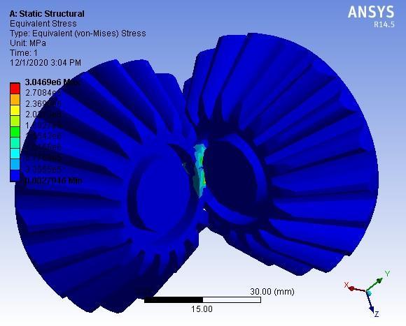
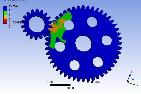
Fig 8: Gear Velocity
Fig 6: IntermediateShaft
Fr= Ft =986.375×tan×tanØ20º=359.011N


Calculations: Velocity= =16.24=m/s © 2022, IRJET | Impact Factor value: 7.529 | ISO 9001:2008 Certified Journal | Page1017
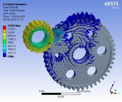
7.5 Dynamic fluid flow analysis on casing 7.6 Dynamic Analysis of gear velocity

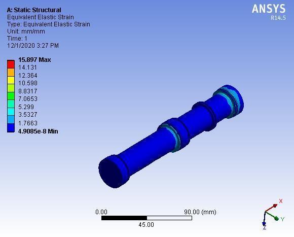
Boundary Condition: In the static analysis boundary conditioncanbeappliedtogeometry,includingfaces,edges, curves,points,meshpoints,verticals,nodes,elementsorthe entire model. The static load of transmission gear act on shaft.TheyaredividedintotwopartsnamelyTangentialand Radialoneachgearhavetoanalysistheseloadareappliedto findtheactualeffectofstressanddeformationongear.
Boundary Condition: Theboundaryconditionistheoneof themajorimportantfactorstogoverntheoutputresultof FEAandloadingconditionorloadsareforces,acceleration or deformation applied to a structure or its components. Load cause deformation, displacement and stress in structures.Applyingtheloadsandboundaryconditionplays a significant role boundary applied whatever needed or requiredsincethatcloselymatchedmotionasloadsactsat the depending on the mannerism of abacus boundary conditionareappliedconditionvariesifexplicitprocedure hadbeenchosendegreeoffreedomrestrictsforbothpinion and gear except the rotational motion therefore it is free rotate the gear is axially and radially constrained that analytically rigid surface used to simulate shaft method is usedandappliedat125radpersecofangularvelocity.
Calculations: Fig 7: FluidFlow WhereFt=P/V ==7457/2.8×2.7986.375N
International Research Journal of Engineering and Technology (IRJET) e ISSN: 2395 0056 p ISSN: 2395 0072Volume: 09 Issue: 02 | Feb 2022 www.irjet.net
REFERENCES
1. Lucian Tudose, Ovidiu Buiga, Daniela Jucan, Cornel Stefanache, Optimal design of two stage speed reducer, 2. Chetan Wadile , Rohan Dubal , Roshan Kolhe , Versha Rangaswamy, Aqleem Siddiqui & Nitin Gurav(2013), 3. Aditya Patankar, Rohit Kulkarni, Sanket Kothawade and Sameer Ingle (2016), Vol.7(3), pp.351 359. 4. Abhinav Sharma, Jujhar Singh and Ashwani Kumar (2015), ‘Optimum Design and Material 322.Selection ofBaja 5. DriveShafts,Serviceinformationmanualno.608, Saginaw steering gear division, General motor corporation,USA 6. UniversalJointsKitsCatalogueUJ76Repco UniversalJointgroup,Australia
© 2022, IRJET | Impact Factor value: 7.529 | ISO 9001:2008 Certified
BIOGRAPHIES
Mr. Swapnil Anil Kumavat is a Graduate Mechanical Engineering Student from SNJB’s Late Sau. KantabaiBhavarlaljiJainCollegeOf Engineering, Chandwad, Nashik, Maharashtra,Indiaandalsoalumni of SAE BAJA Collegiate Club and servedasaSuspensionHeadinhis Mteam.r.ShreyasRajendraKshirsagaris a Final year Mechanical Engineering, student from Sandip Institueoftechnologyandresearch center (SITRC), Nashik, Maharashtra, India and currently serving as a team captain in his SAEBAJAIndiateam. Mr. Darshan Pratap Jat is a Graduate Mechanical Engineering student from MET Institue of Engineering, Bhujbal Knowledge City,Nashik,Maharashtra,India Mr Shubham Uddham Sutar is a Graduate Mechanical Engineering student from MET Institue of Engineering, BhujbalKnowledge City,Nashik,Maharashtra,India


Journal | Page1018 8. CONCLUSION
Thispaperunveilstheadditionalrefinedmethodologyofthe AWDshellplanningwhilenotvictimizationtransferscase.By shaping the load spectrum within the program additional realisticdrivingandasaresultdesignercandoadditional correctresultsofstrength, equivalentstress,deformation, safetyfactorsandalternativesuchparameters.

International Research Journal of Engineering and Technology (IRJET) e ISSN: 2395 0056 p ISSN: 2395 0072Volume: 09 Issue: 02 | Feb 2022 www.irjet.net = = =3.326m/s2
Acceleration
