Jagdish Pathade5
1.INTRODUCTION
SwatantriSomkuwarDilip 2 Mechanical Department Vishwakarma Institute of Pune,TechnologyIndia. Bhumika Sunil Pawar3 Mechanical VishwakarmaDepartmentInstituteof Technology Pune, India. Prof. Rajkumar Bhagat6 Mechanical VishwakarmaDepartmentInstituteofTechnology,Pune,India.
DESIGN AND DEVELOPMENT OF ELECTRO-MECHANICAL LIFTING JACK
Abstract-------------------------------------------------------------------------------***----------------------------------------------------------------------------Powerscrewsarewonttoconvertmotilityinto translatory motion. A mechanical jack is an example of an influence screw within which a tiny low force applied duringahorizontalplaneisemployedtoboostorloweran oversized load. The advantage of a mechanical jack is that theratiooftheloadappliedtothehassleapplied.thepeak of the jack is adjusted by turning a lead screw and this adjustment is done either manually or by integrating an electrical motor. the planning and modification of quick lifting jackscrew with gear arrangements that are safe, reliableandcapableofraisingorloweringheavyloadwith little effort. This mechanism consists Lead screw, Bearing, Lead screw nut and assembly, Lead screw driving mechanism, Motor, structure, Lead screw selection. So, duringthisresearchpaperwedesignandanalysethelead screw against eccentric load The designed motorised jack will save time and requires less human energy to control. Generally, jacks undergo buckling once they reach maximum load conditions (as per the tests conducted by consumeraffairs).Forthisreason,we'vegottodevelopthe system which might use toggle jack which is automatic operatingusingmotor.Vehicle’sbatteryareoftenusedasa sourceofpowerforthismotor.thecurrentstudyprovides automated and simplified levelling system to help the levelling of the vehicle simultaneously reducing the manualinvolvement&effort.
Keywords Screw Jack, Eccentric Load, Lead Screw, DC Motor, Horizontal levelling, Torque, Gear ratio.
DGM Deputy ManagerGeneral Bharat Electronics Limited Navi Mumbai Bikash Das4 Senior Engineer Bharat Electronics Limited Navi Mumbai Prashil Umesh Patil1 Mechanical VishwakarmaDepartmentInstituteofTechnologyPune,India.
This system consists of lead screw, motor, gear box, bearings,nut.Shaftisconnectedtotheleadscrewthrough gear box arrangement. The gear box consists spur wheel arrangement. gear wheel can help to transfer the torque from motor shaft to steer screw. the matter under our consideration is to style lead screw for eccentric load on that for any application like our project. The lead screw also called power screw utilized in machine to translate rotation in to linear motion. The lead screw is compact, simple in design and having large load carrying capacity. Lead screw has wide application in various mechanism. A Jackscrew may be a style of jack which functions by turningaleadscrew.it'scommonlywonttoliftheavyload toa height.anhonestexampleis thatthecar jacks.within the case of a jackscrew, a little force applied within the horizontalplaneisemployedtoliftorlowerlargeload.The statement of problem has led to the motivation of designing a modified quick lifting jackscrew with gear arrangement. In day to day life it's very tedious job to control the jack manually and it's also a really time consuming work further. the overall idea of project is to attenuate the human effort while operating the jack. A mechanical jack could be a portable device consisting of a screwmechanismwanttoraiseorlowertheload.themost parts of mechanical jackscrew (cylindrical) jack are Body, Screw, Nut and Thrust Bearings. The principle on which the jackscrew works is analogous to it of an machine. The jack is created out of varied varieties of metal, but the screw itself is usually made out of lead. While screw jacks are designed purposely for raising and lowering loads, they're not ideal for side loads, although some can withstand side loads looking on the diameter and size of the lifting screw. Shock loads should even be avoided or minimized. Some screw jacks are built with anti backlash. The anti backlash device moderates the axial backlash within the lifting screw and nut assembly to a regulated minimum. great deal of warmth is generated within the jackscrew thanks to friction between various parts and long lifts can cause serious overheating. To retain the efficiencyofthejackscrew,itmustbeusedunderambient
INTERNATIONAL RESEARCH JOURNAL OF ENGINEERING AND TECHNOLOGY (IRJET) E ISSN: 2395 0056 VOLUME: 09 ISSUE: 02 | FEB 2022 WWW.IRJET.NET P ISSN: 2395 0072 © 2022, IRJET | Impact Factor value: 7.529 | ISO 9001:2008 Certified Journal | Page96


Abearingisa machineelementthatconstrains relative motiontoonlythe desiredmotion,andreduces frictionbetweenmovingparts
When jack diagonally touching the ground MomentaboutA: m@A=35*3448.25 F3(8281.28)
ALTERNATE MomentaboutA:m@A=F2(8093) 35(3338) MomentF2=14.43TaboutB:m@B=F1(8093) 35(4755)
driving mechanism (Motor): a machinethat suppliesmotivepowerforavehicleorotherdevicewith movingparts.
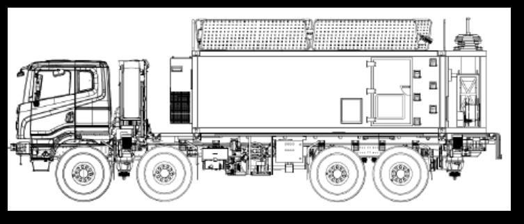
3.1CALCULATING LOAD ACCORDING TO CG
3.2DESIGN OF LEAD SCREW MECHANISM
CASE1:Accordingly,
3. DESIGN PROCEDURE
INTERNATIONAL RESEARCH JOURNAL OF ENGINEERING AND TECHNOLOGY (IRJET) E ISSN: 2395 0056 VOLUME: 09 ISSUE: 02 | FEB 2022 WWW.IRJET.NET P ISSN: 2395 0072 © 2022, IRJET | Impact Factor value: 7.529 | ISO 9001:2008 Certified Journal | Page97 temperatures, otherwise lubricants must be applied. The screw contains a thread designed to resist an unlimited amountofpressure.thiscanbethankstotheveryfactthat it's generally holding up heavy objects for an extended amount of your time. Once up, they normally self lock so they will not fall if the operator lets go, and that they waitingwelltothewearandtearofrepeateduse.it'smade from a bolt and nut assembly and its working rule is analogous to it of an simple machine. Where a thread wound round a shaft rotates in its bearings while the nut hasrevolutionagainsttheresistingaxialforce.Thisproject isgearedtowardsresearchinganddevelopingajackthat's power operated, time saving and more efficient. Thus, achieving one amongst the goals of technology by making lifeeasierforthetipuser,properdesignconsiderationsgot to the look of this project including the stresses, bending moment of the shafts, strength of materials and also the maximum load it's expected to hold, thus making safety andreliability.
Leaddevicesscrew
The system is lifted and leveled using 4 jack, two fitted at thefrontandtwofittedattherearofthesystem.Capacity ofjackisdecidedinsuchawaythattwojackatatimecan take load of the overall system. The overall Cg and Jack location are shown in a schematic diagram below. Here, two cases are considered one is diagonal and other is alternate.
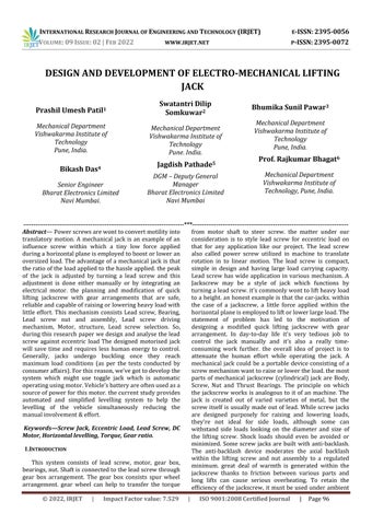
LeadScrewdesigninleadscrewselectionprocess,wefind out length of lead screw, material selection for screw and nut, outer or major diameter, minor diameter, pitch diameter,pitch,lead,typeofthread. ● Material selection. ● `Material for screw is steel. Material for nut is cast iron. We have considered following material properties: Fig1[1]. Fully loaded TATA Defence Combat 8X8
F1= CASE2:20.4T
Leadscrewnutandassembly:Leadscrewsarethreaded bars of metal and a threaded nut which is in direct contactwiththescrew;thisgeneratesslidingfrictionas opposed to rolling friction from other alternative
F1= Maximum20.56Tloadis20.56Tso 22T loadistaken.
F3= Moment14.57TaboutC:m@C=35*4833.03 F1(8281.28)
2. COMPONENTS OF POWERED JACK Leadscrew:Aleadscrew,alsoknownasapowerscrew ortranslationscrew,isascrewthatisusedasalinkage in a machine to translate rotary motion into linear Bearing:motion.
3.2.4 Torque Calculation Load:Pr=Ftan(θ+λ)=34804 b. Torqueforraisingload:Tr=Pr*dm/2=1131.3
3.2.5 Stress Calculation for checking design is safe Torsionalstress:ζ=16*Tr/3.14*dc³=26.68MPa Principlestress:σx=[W/(π/4*dc²)]/2=77.84 Maximumprincipalstress:σ1=σx/2±=86.1067 DESIGNOFNUT Parameter Value Yield stress of selected Nut material 152MPa from table(Pu)
.noSr
1.
2. Shear Stress of selected Nut material 100MPa 3. Value of unit Pressure
c.
INTERNATIONAL RESEARCH JOURNAL OF ENGINEERING AND TECHNOLOGY (IRJET) E ISSN: 2395 0056 VOLUME: 09 ISSUE: 02 | FEB 2022 WWW.IRJET.NET P ISSN: 2395 0072 © 2022, IRJET | Impact Factor value: 7.529 | ISO 9001:2008 Certified Journal | Page98 Srno. Parameters Values 1. Yield strength ofmaterial 330MPa 2. Shearstrength ofmaterial 170MPa 3. Young’s Modulus 200GPa 4. Coefficient of friction 0.1 5. Factor of safety 3 6. Nut factor weighheight 2 3.2.1 Stress calculations: PermissibleCompressivestress=330/3=110N/mm² Directcompressivestressσc=Wc/Ac dc²=(4*22*10000)/3.14*110.dc=50.47mm Majordiameterdm=d p/2=65 3.2.2 Lead Calculation l = n* p*(5)= 10 mm 3.2.3 Calculation of Coefficient of friction
11MPa 4. Coefficientoffriction 0.1 5. Factorofsafety 3 6. Nutfactorweighheight 2 7. TypeofScrew screwJack 8. Materialofscrew Steel 9. MaterialofNut IronCast 10 Bearingstress 17MPa12 11 Lowspeed <2.5 TABLE II TABLE I
3.3
The coefficient of friction steel screw &Cast iron nut is normally taken as 0.1 the maximum possible value of coefficient of friction is 0.18 this occurs when, friction occurs maximum on account of poor lubrication we will consider the worst condition where the operator is carelessaboutthelubricationofthescrew.
a.
a.
b.
INTERNATIONAL RESEARCH JOURNAL OF ENGINEERING AND TECHNOLOGY (IRJET) E ISSN: 2395 0056 VOLUME: 09 ISSUE: 02 | FEB 2022 WWW.IRJET.NET P ISSN: 2395 0072 © 2022, IRJET | Impact Factor value: 7.529 | ISO 9001:2008 Certified Journal | Page99 3.3.1 Determining height of nut a. t = thickness of screw = p/2 = 10/2 = 5mm b. H=heightfactor*pitchdia=130mm c. N=no.ofthreadsengaged=13 d. Bearing stress = load/Area = (4*22*10000)/3.14(70² 60²) = 16.58MPa 3.3.2 Calculating stress values 3.3.2.1Transverse shear stress in Nut a. Rs(Nut)=W/πndct=11.6MPa b. F.O.S=Allowableshearstress/stress=8.62 3.3.2.2Compression stress in Nut a. σc(Nut)=W/πn(dmajor² dc²) =2.69MPa b. b. F.O.S = Allowable compressive stress / stress=56.5 c. c. OuterdiameterofNutD=87.76mm 3.3.3 Checking for self locking Condition πμdm>10=>0.1*3.14*65>10=>20.41>10 3.3.4 Checking for Buckling a. I=π/64*(dc)´=0.635850*10 ⁶ b. r=√I/√A=15mm c. StrokeLength=477 d. Slendernessratio=λ=l/r=76.93 As intermediate column is from 40 120mm we have takentheIntermediateColumn. 3.3.4.1 Condition: one end free and other fixed leff=2l=2*577=1154mm a. Pe=π²EI/(leff²)==1035.6786*10³N b. Pc=fcA=817321.40N c. c. Pr=10⁶(0.4568172)=4568172 ForIntermediateColumn;EmpiricalFormulae WcrbyEuler'sFormulaisPcr d. CheckingF.O.S=Pcr/220000=4.707 3.4 GEARBOXDESIGN Srno. Parameter Value 1. timeDeployment 180secs 2. StrokeLength 477 3. Diameter of screw 60mm 4. Leadofscrew 10mm 5. Frequency 50Hz 6. MotorSpeed 960RPM 7. Gearratio 1:60 8. Torque 1131.130Nm 9. EfficiencyScrew 0.85 10. Gearbox 0.85 a) LinearspeedofNut=477/180=2.65mm/s b) Rotation required to raise load by 477mm = 477/10=48 c) RotationSpeed=48/3=16RPM d) Gearratio=16/960=1:60 e) Th.Power= 2*3.14*NT/60=2*3.14*16*1131/60 =1895· TABLE III
1.
3.15 BEARINGSELECTION
4.
a. We selected taper roller bearing because, The lineofactionoftheresultantreactionmakesan anglewiththeaxisofbearing.
b. This reaction can resolve into radial and axial component “Tapper roller bearing is suitable forcombinedaxialandradialloading.”
4.
5.
INTERNATIONAL RESEARCH JOURNAL OF ENGINEERING AND TECHNOLOGY (IRJET) E ISSN: 2395 0056 VOLUME: 09 ISSUE: 02 | FEB 2022 WWW.IRJET.NET P ISSN: 2395 0072 © 2022, IRJET | Impact Factor value: 7.529 | ISO 9001:2008 Certified Journal | Page100 f) Actual Power = 1895/0.85*0.85 = 2622W (Approx. 3kW) N2/N1=1/60=1/2×1/2×1/3×1/5 Takingspurgearofmodule 1.5 3.5 GEARARRANGEMENT 3.6 SPEEDOFSHAFTS 3.14 DETERMININGDIAMETEROFSHAFTS
Shafts Speed(RPM) 1. Shaft1 960 2. Shaft2 480 3. Shaft3 240 4. Shaft4 80 5. Shaft5 16 Sr
Sr
150 Sr
d.
m)Torque(N mm)Diameter( DiameterApprox. 1.
11 15 TABLE TABLEIVV TABLE VI
9 Sr
c. The conical surface of each roller is suitable to pressure, which acts to the normal to the surfacetherefore“Iftheexternalforceactingon the bearing is purely radial it induced a thrust reaction within a bearing to avoid the separation of cup from cone. This thrust traction must be balanced by equal and oppositeforce. This is balanced by at least two taper roller bearings on the same shaft, so we are using samebearingforbothends. no. Shaft (mm)diameterOuter Width(mm) Shaft1 62 17 2. Shaft2 37 no. 1stgear 30 2. 2stgear 40 60 3stgear 60 90 4stgear 100 no. no. 358.2 26 119 18 20 119.4 18 20 59 14 20 29.5
20
30 2.
3.
3.
Gear Teeth Diameter 1.
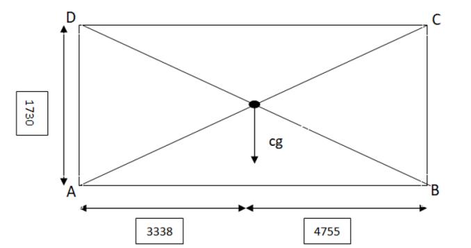
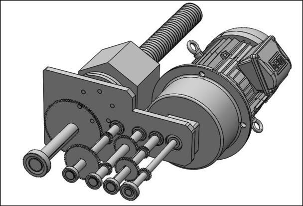
INTERNATIONAL RESEARCH JOURNAL OF ENGINEERING AND TECHNOLOGY (IRJET) E ISSN: 2395 0056 VOLUME: 09 ISSUE: 02 | FEB 2022 WWW.IRJET.NET P ISSN: 2395 0072 © 2022, IRJET | Impact Factor value: 7.529 | ISO 9001:2008 Certified Journal | Page101 3. Shaft3 37 9 4. Shaft4 37 9 5. Shaft5 62 9 4. SOLIDWORKS DESIGN TABLE VII Fig2.Four view of Design Fig3. Gears Representation Fig4. Isometric view Fig5. Exploded view of Design Assembly Fig6. Design Assembly


Gopinath, Design, Simulation and Demonstration of a Parallel Parking Mechanism foraCityCar,1998 [4] A.A. Thomas, Lifting and Sideward Driving MechanismforAutomobiles,2090768,1937 [5]PinYeh,StructureofLateralDrivingdevicefor car,US4998595A,1989 [6] [1] V.B.Bhandari, Design of machine elements, 3rdEdition,TataMcGrawHill,2010
Fewimprovementscouldbedoneinthefuturetoincrease safetyandreliability 1. Thegearscanbeimprovedbyreplacingspurgear intobevelgears. 2. The gear arrangement can be more compact so that there should be no extra load on the vehicle ortheplatform
We expressourdeepestgratitudeandheartfeltthanksto our guide, Professor Rajkumar Bhagat (Mechanical Department), for his expert guidance, constant encouragement, constructive criticism, and inspiring advice throughout the completion of this report. We are thankful to the Mechanical Engineering Department, VIT Pune who provided us this opportunity to explore the topicthroughthisevaluationcomponent.Wearegrateful to Prof.Dr. M.B. Chaudhari sir HOD, Department of Mechanical Engineering for such a helpful component in academics for being our guardian same, guiding us over weeks to improve upon our progress. Last but not least wewouldliketothankProf.Dr.RMJalnekarsirforgiving ustheseopportunities.
7. FUTURE SCOPE
INTERNATIONAL RESEARCH JOURNAL OF ENGINEERING AND TECHNOLOGY (IRJET) E ISSN: 2395 0056 VOLUME: 09 ISSUE: 02 | FEB 2022 WWW.IRJET.NET P ISSN: 2395 0072 © 2022, IRJET | Impact Factor value: 7.529 | ISO 9001:2008 Certified Journal | Page102 5. RESULTS Srno. Parameters Value 1. Jacktype mechanicalElectro 2. Capacity 22T 3. Strokelength 477mm 4. Lead screw diameter 60mm 5. Lead screw pitch 10mm 6. Nutsize 130mm 7. Gearratio 60:1 8. timeDeployment 180secs 9. Powerinput 3KW 10. Inputspeed 960RPM 11. Inputtorque 597Nmm 6. CONCLUSION Design of complete jack and its components under different loading conditions is studied and its principal dimensionsarefoundout.Samespecificationscanbeused for manufacturing and be given to jack manufacturers for production. Also,thedesignofnut,geardesignalongwith determining diameter and speed of shafts and bearing selectionisdone.
8. ACKNOWLEDGEMENT
9. REFERENCES [1] Karl t Ulrich, Anita Goyal, Product design and development 4th edition, TATA McGraw Hill publication,pp32 1422009 [2] Shigley’s Mechanical Engineering Design, 8th edition, TATA McGraw Hill publication, pp597 652, [3]Varun2009
TABLE VIII:
TECHNICAL SPECIFICATIONS