Operatingtheengineatahighequivalenceratio,changein fuel phase as the engine structure heats after ignition and changeinfuelcompositionwithvariationinthethermalload oftheenginestructurearetheotherchallengesfacedduring fuelinjection.
3Third year student, Mechanical Department, Meenakshi Sundararajan Engineering College, Tamilnadu, India ***
There are inherent losses in the supersonic incoming airstream.Additionallossesduetofuelinjection,mixingand combustion, shock wave loses, pressure and friction drag, shearlayermixinglossesandlossofmomentumoffueljets shouldbekeptminimumwhilstthecompletefuel airmixing andfuelchemicalreleasemustbeachievedmaximum.
Injector design, injector placement, mixing features and flameholdingarethepropertiesthatareimportantforany robust combustion system designed to operate over very shortresidencetimes.
Theramjetengineconsistsofthreeregions: Diffuser Nozzle Combustionchamber
1.INTRODUCTION
The location of the heat release should be managed relativetotheappropriateflowareawithinthecombustor foracceleratingthevehicle.Peakpressuretooforwardcan change the inlet conditions whereas peak pressure too backwardsdecreasesthecombustorinletpressure.
MIXING OF LIQUID KEROSENE IN A SUPERSONIC CROSSFLOW FOR A SCRAMJET ENGINE
Theflowgetsdeceleratedtosubsoniclevelinthediffuserand thecombustionhappensinthechamber. Thentheflowis accleratedtosupersoniclevelusingadivergentnozzle.The onlydifferencebetweenramjetandscramjetenginesisthat inthelattertheflowisnotdecleratedtosubsoniclevelsin thediffuser.
1.1 AIR BREATHING RAMJET AND SCRAMJET ENGINES
Ramjetenginesdoesnothaveanybigmovingparts.Instead theforwardmotionoftheengineisusedtocompresstheair.
International Research Journal of Engineering and Technology (IRJET) e ISSN: 2395 0056 Volume: 09 Issue: 02 | Feb 2022 www.irjet.net p ISSN: 2395 0072 © 2022, IRJET | Impact Factor value: 7.529 | ISO 9001:2008 Certified Journal | Page946

1Assistant Professor, Mechanical Department, Meenakshi Sundararajan Engineering College, Tamilnadu, India
Abstract - Even after decades of development, aircrafts still travel at subsonic speeds. This can be changed by using supersonic vechiles with air breathing engines in this case the scramjet engine. Many difficulties are encountered while designing highly efficient combustion systems. Fuel penetration and mixing of fuel are considered as primary parameters. Basic parameters for effective mixing of fuel in scramjet engine are Height of penetration and Plume spread area. Since height of penetration and plume spread area are proportional to momentum flux ratios this is considered as prime parameter to work on. Injection pressures which is a direct function of momentum flux ratio are varied. For different injection pressure regimes are set up and the consequence of varying J ratios for individual injectors are evaluated. The varying J ratio accounted for the variation in penetration and mixing are qualitatively studied. Using MIE respectusingthevariousscatteringflowvisualisationtechniqueimagesarecapturedatdistancesinordertogathermoreinformationaboutpenetration.TheseimagesareprocessedusingMATLABwhichtheareaofplumeandheightofpenetrationwithtodifferentmomentumfluxratioswerecalculated.
Researchstudiesfordesigninganoptimalinjectorthatfulfils allaboverequirementsforairbreathingpropulsionsystems for hypersonic or supersonic flight is yet to be developed.
Vadivel M1, Vignesh S2, Suhas P S3
Key Words: Supersonic crossflow, Scramjet engines, Mixing of fuels, Fuel penetration, Plume spread area
2Third year student, Mechanical Department, Meenakshi Sundararajan Engineering College, Tamilnadu, India
Aviationandspaceindustrieshavedevelopedalotinthelast 100 years, but still the fastest planes travel at subsonic speeds while rockets reach escape velocities and deploy satellitesintoorbit.Thismassivedifferenceinspeedcanbe broughtdownbytheuseofsupersonicvehiclespoweredby airbreathingjetengines. There are many difficulties encountered while designing highlyefficientcombustionsystemswithwideoperability.
Theeffectivefuelinjectionisoneofthemainproblemsasthe fuel has very short combustor residence times, compressibilityeffectscausepoormixingandreactionmust occuralmostInstantaneously.
Many injector concepts are developed and tested for differenthighspeedpropulsionsystems.
2. SCRAMJET FUEL INJECTORS
Absence of an optimal injector design and lack of reliable analytical tools are the massive challenges for the developmentofhigh speedpropulsionsystems.
uair
uair
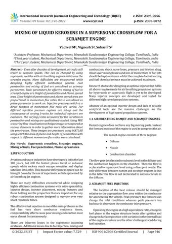
Fig 1 : ExperimentalLayout
Fuel
There is an opening at the front end of the test section to provideairflowtotheexhaustoftheairandfuelmixture.The chamberhasaflangedmouthairintake.Oneendoftheflange isfittedtothesettlingandtheotherendisattachedtothe test section. Two metal plates with windows are bolted orthogonallytotheairflowatthisendofthechannelcreating atestsection.
The setup consists of a settling chamber, rectangular air supply chamber, test section containing an injector under investigation and two windows for optical access to the spray. Air is supplied to the test section from the main compressorlinealongthesettlingchamber.
Theexperimentalsetupdevelopedbythenationalaerospace laboratory,propulsiondivision,Bangalorewasusedforthis experiment.
4. CALCULATION OF MOMENTUM FLUX RATIO The experiment is carried out at different J ratios J=ρfuelu2fuel/ρairu2air Densityofthefuelρfuel 800Kg/m3 ufuel = (2(pL ps)/ ρfuel)0.5 P0/Ps=[1+( 1)/2*M2]/ 1 2.89/0.408=[1+(1.4 1)/2*M2] 1.4/(1.4 1) M= 1.93 To/Ts=1+( 1)/2*M2 300/Ts=1+(1.4 1)/2*1.932 Ts = 171.92K ρair =Ps/ Rts ρair =0.408/(287*171.92)=0.826 Kg/m3 uair
variousanalyseddistanceImagesaccuratevisualisationvisualisationTovariationinjectorssetForfunctioninwasthePenetrationheightandplumespreadareaareproportionaltomomentumfluxratiothereforethisparameteroffueljettheprimeconsiderationtoworkon.Injectionpressuressupersoniccrossflowexperimentsarevaried,whichisaofmomentumfluxratio.differentinjectionpressures(4,8,12,16bars)regimesareupandtheconsequenceofvaryingJratiosforindividualareevaluated.ThevaryingJratioaccountedfortheinpenetrationandmixingarequalitativelystudied.gathermoreinformationofthepenetration,aflowtechniquehadtobeused.MIEscatteringflowtechniqueisusedasitiseasytooperate,andrequiresshortexperimenttime.arealsocapturedatdifferentpositionsatarelativetotheMIEsetup.TheseimageswillbequalitativelytoevaluatejetpenetrationandspreadfortheJratios. = M( RTs)0.5 =1.93(1.4*287*171.92)0.5 = 503.86 m/s PressureinjectionP1 (bar) Momentum flux ratio (J) 4.239 3.7 8.2867 7.7 12.216 11.6 16.25 15.3
International Research Journal of Engineering and Technology (IRJET) e ISSN: 2395 0056 Volume: 09 Issue: 02 | Feb 2022 www.irjet.net p ISSN: 2395 0072 © 2022, IRJET | Impact Factor value: 7.529 | ISO 9001:2008 Certified Journal | Page947 Scramjet engines cruise and accelerate at a high equivalence ratio which requires injectors with adequate penetration and rapid dispersion within the high speed crossflow. 3. SCOPE OF THE EXPERIMENT Two basic parameters for the effective mixing of fuel in scramjetengineare Heightofpenetration Plumespreadarea
By varying the injection pressures we can vary the momentumfluxratios.Forthefollowingpressurestheabove tabulatedJratiovalueswerefound.
5. EXPERIMENTAL SETUP
Twoquartzwindows1/8inchesthickarefixedintheslotsof themetalplatesusingrubbergaskets.Astandoverthetest sectionisprovidedtomountheatertoavoidcondensationof moisturearoundthewindows.Afuelinjectorislocatedon thecentrelineofthehorizontalplate.Theentireassemblyis installedonafixedmetalpillarwhichsupportstheassembly
Minimumandmaximumintensityvaluesareobtainedfrom theprocessedimagewhichisprovidedastheinputstofind thefuelpenetrationandfueldispersion. Imagesarecapturedforfourmomentumfluxratiosatfive different downstream positions for each momentum flux ratios.
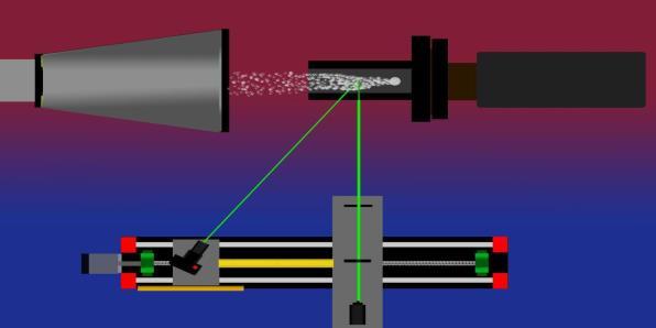
Imagesarecapturedatfivedifferentdownstreamdistances frominjectorpositionandatdifferentmomentumfluxratios whichareafunctionofinjectionpressureandprocessedin MATLAB. MIE scattering technique is used for the visualisation of the fuel air mixture in the test section for imageprocessing. Largenumberoffuelmoleculesarepresentneartheinitial positionofthelaserproducinghigherintensityimagewhilst 40mm from the injector position the molecules are distributed all over the session producing lower injection imagewhichisshownbelow.
Thesheetisperpendiculartotheflowinsidethewindtunnel, illuminatingtheplaneattheinjectionpoint.
7. IMAGE PROCESSING
Thisisdoneforthreemoresteps,i.e.,uptofiveregimesalong theflow.Uponcompletingtheabovestepsandonpressing the forward switch again, the traverse moves backwards, positioning the channel back to zero position. Now, the injection pressures are changed to 8, 12 and 16bar as different cases and the same procedure is carried out for capturingtheflowimages.
Onpressingtheforwardbuttoninthetraversecontrol,the channel moves to the next step resulting in a laser sheet focussingonthesecondregimeinthetestsection.Againat thispositionpicturesarecapturedbythecamera.
The two windows of the test section are parallel to each other to provide optical access for the light source and camera to distinguish the spraying from both sides. This allowedforthecapturingofflowimagesatdifferentplanes alongthetestsection window.Mie scattering visualisation technique was adopted in this testing, which consists of a laser light source ,cylindrical lens and a spherical lens all mountedinthesameordertoformasheetoflaserwhichis incident onto the section window. It provides precise movementontheopticalbenchinadirectionsimilartoair flowusingstepmotorsandelectronicdrivers.

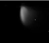
Fig 2 : ExperimentalSetup
The above images are taken at initial and final positions for momentum flux ratio j=3.3.

Thefuelsupplyswitchisturnedonandtheinjectionpressure issetto4barforthefirstcaseoftheexperiment.Constant injectionpressureismonitoredfromthecontrolroomandon achievingthesame,threetofourpicturesarecapturedbythe camerafocusingontheregime.
At Injection pressure pinj=4.3 bar , Momentum flux ratio j=3.7 X=0mm X=10mm X=20mm X=30mm X=40mm
atdifferentpositionsinsuchawaythatallareparalleltothe ground.The design of the test section provides full confinementofairflowinthesprayregion.
Volume: 09 Issue: 02 | Feb 2022 www.irjet.net p ISSN: 2395 0072 © 2022, IRJET | Impact Factor value: 7.529 | ISO 9001:2008 Certified Journal | Page948
At x=0, j=3.3 At x=40mm, j=3.3
International Research Journal of Engineering and Technology (IRJET) e ISSN: 2395 0056
6. WORKING Afterinstallationoftheapparatusontheopticalbench,the laserlightsourceisturnedonandthelasersheetisformedas aconsequenceoflaserlightpassingthroughacylindricallens followedbyasphericallensmadeincidentonthetestsection.
Thispositioninthetraversingapparatusismarkedaszero point.Thisisfollowedbyturningonthepowersupplytothe traverseapparatus.Theflowcontrolvalveinthesupplyline of the wind tunnel is opened. The total gauge pressure is ideallymaintainedat2barfortheexperiment.
Atinjection pressure pinj= 8.3 bar, momentum flux ratio j=7.7
International Research Journal of Engineering and Technology (IRJET) e ISSN: 2395 0056 Volume: 09 Issue: 02 | Feb 2022 www.irjet.net p ISSN: 2395 0072 © 2022, IRJET | Impact Factor value: 7.529 | ISO 9001:2008 Certified Journal | Page949 X=0mm X=10mm X=20mm X=30mm X=40mm At injection pressure Pinj = 12bar, momentum flux ratio j=11.6 X=0mm X=10mm X=20mm X=30mm X=40mm AtinjectionpressurePinj =16.2bar,momentumfluxratio j=15.3 X=0mm X=10mm X=20mm X=30mm X=40mm 8. PLUME SPREAD AREA Foreveryfuelinjectionimageatdifferentpositionscapturing thematvariousfuelinjectionpressures,theareaoftheplume will vary accordingly. The area of the plume is calculated usingMATLABanditisgivenintheformofpixels.Wehave takenareferenceareaofknowndimensionandthenumber ofpixelsofthatreferenceareaarefoundanddivided,which givestheno.ofpixelspermm2 1mm2 ofarea=3672pixels For J=3.7 Initial position Theareacalculated=3.885862e+04pixels 1mm2 =3672pixels Areaoftheplume=3.885862e+04/3672=10.5825mm2 8.1 AREA OF PLUME AT VARIOUS POSITIONS ACCORDING TO MOMENTUM FLUX RATIOS FormomentumfluxratioJ=3.7 Position 1 2 3 4 5 Area of (mmplume 2) 10.5825 38.9869 149.9 72.25 585.408 FormomentumfluxratioJ=7.7 Position 1 2 3 4 5 Area of (mmplume 2) 18.2498 51.43 576.5 80.25 113.3 FormomentumfluxratioJ=11.6 Position 1 2 3 4 5 Area of (mmplume 2) 18.616 66.69 81.31 84107.1 7124.8 FormomentumfluxratioJ=15.3 Position 1 2 3 4 5 Area of (mmplume 2) 18.78 73.1 95.25 6123.6 4127.0 8.2 HEIGHT OF PENETRATIONS AT VARIOUS POSITIONS ACCORDING TO MOMENTUM FLUX RATIOS FormomentumfluxratioJ=3.7 Position 1 2 3 4 5 Height (mm)penetrationof 5 8.80 9.75 11.50 12.413 FormomentumfluxratioJ=7.7 Position 1 2 3 4 5 Height (mm)penetrationof 6.38 12 12.061 13.53 15.040 FormomentumfluxratioJ=11.6 Position 1 2 3 4 5 Height (mm)penetrationof 7.73 14.57 14.69 16.30 17.05

Fig 5: TheoreticalVsExperimentalPenetrationValues
We would like to thank Dr.K.S. Babai, the Secretary; Dr.P.K.Suresh,thePrincipal;Dr.K.Balasubramanian,H.O.Dof MechanicalDepartment;Mr.M.Vadivel,AssistantProfessor, MechanicalDepartment,MeenkshiSundararajanEngineering
10. CONCLUSIONS
DownstreamdistanceVsFuelpenetration
Foreffectivecombustionoffuelinascramjetapplication,itis importanttoconsidertheparameterslikemixingoffuel.A comprehensiveseriesofexperimentsforkeroseneinjected intosupersoniccrossflowatM=2werecarriedout.
Jet penetration and fuel spread into the crossflow was found to be proportional to momentum flux ratioofthefueljettocrossingairintheinvestigated rangebetweenmomentumfluxratioj=4andj=16 duetoself explaineddependenceofpenetrationon jetvelocity.
Fuelspreadincreaseswithincreaseinmomentum fluxratioalongthedownstreamdistancelinearly.
The experimental penetration values and the theoretical penetrationvaluesarefoundtoincreaselinearlyalongthe downstreamdistances.
International Research Journal of Engineering and Technology (IRJET) e ISSN: 2395 0056 Volume: 09 Issue: 02 | Feb 2022 www.irjet.net p ISSN: 2395 0072 © 2022, IRJET | Impact Factor value: 7.529 | ISO 9001:2008 Certified Journal | Page950 FormomentumfluxratioJ=15.3 Position 1 2 3 4 5 Height (mm)penetrationof 9.43 16.34 17.52 19.33 19.78 9. ANALYSISFig3:
The following conclusions were made from the series of experimentscarriedoutintheinvestigation.
The experimentally measured penetration values were comparedwiththeoreticalvaluesobtainedusingempirical formulae to check for the validity of the experiment. Empiricalformulasforfindingpenetrationis y/de =3.8*(x/de)0.25*J0.4
Fig 4: DownstreamdistanceVsFueldispersion
Thex/dvs.y/dgraphfordifferentmomentumfluxratios(J ratios) is plotted. It can be concluded that, as the J ratio increases,thepenetrationincreases


ACKNOWLEDGEMENT
Thex/dvs.A/d2graphisplottedfordifferentJratios.AstheJ ratiokeepsincreasing,the“Area ofPenetration”(A)keeps increasing.Thisisanalysedatdifferentpositions,startingat theinjectorposition.Thediameteroftheorificeisgivenas (d).It was observed that as the momentum flux ratio increased, the spread of the fuel increased. The trend remained the same along the downstream, i.e., the spread increased. It was observed that increase in spread with increaseinJratioisnotsignificantattheinjectionpoint.
Penetration of fuel increases with increase in momentumfluxratiowasfoundtobesignificantat locationsclosertotheinjection.
E.Lubarsky,D.Shcherbik,O.Bibik,Y.GopalaandB. T.Zinn“FuelJetinCrossFlow ExperimentalStudy of Spray Characteristics,” School of Aerospace Engineering,GeorgiaInstituteofTechnology.
Raymond P. Fuller,* Pei Kuan Wu,f and Kevin A. Kirkendallt Taitech,Inc., Dayton, Ohio 45431 and AbdollahS.Nejad“EffectsofInjectionAngleonthe Breakup Processes of Liquid Jets in Subsonic Crossflows” Wright Laboratory, Wright Patterson AirForceBase,Ohio45433.
K.M.Pandey, Member IACSIT and T.Sivasakthivel” Recent Advances in Scramjet Fuel Injection” InternationalJournalofChemicalEngineeringand Applications, Vol. 1, No. 4, December 2010 ISSN: 2010 0221.
College, in providing us continuous support towards the developmentofthisjournal.
REFERENCES
Yates, C. L “Liquid Injection Into a Supersonic Stream” AFAPL TR 71 97, Vol 1, 1972 [14] Raymond Fuller, Pei Kuan Wu, Kevin Kirkendall, Abdollah Nejad, Raymond Fuller, PeiKuan Wu, Kevin Kirkendall, and Abdollah Nejad. "Effects of InjectionAngleontheBreakupProcessesofLiquid jetsinSubsonicCrossflows",33rdJointPropulsion Conference and Exhibit, Joint Propulsion Conferences
Rogers, C. R., Capriotti, D. P., and Guy, W. R., NASA“ExperimentalSupersonicCombustionResearchatLangley,”AIAAPaper 1998 2506,1998.
Lin,K C.,Kennedy,P.J.,andJackson,T.A.,“Structures ofWater JetinMach1.94SupersonicCross flow”, AIAAPaper2004 0971,2004.
S.M.Yaya “Fundamentals of compressible flow for aircraft and rocket propulsion” sixth edition, publishedbyNewAgeScience.
P.K.Nag “Engineering Thermodynamics”, sixth edition,McGrawHillPublications.
Chung JenTam,SusanCox Stouffer,Kuo ChengLin, Mark Gruber, and Thomas Jackson. "Gaseous and LiquidInjectionintoHigh speedCrossflows",43rd AIAA Aerospace Sciences Meeting and Exhibit, AerospaceSciencesMeetings.
International Research Journal of Engineering and Technology (IRJET) e ISSN: 2395 0056 Volume: 09 Issue: 02 | Feb 2022 www.irjet.net p ISSN: 2395 0072 © 2022, IRJET | Impact Factor value: 7.529 | ISO 9001:2008 Certified Journal | Page951