Abstract In this paper an attempt is made to explore the performance of G+9 storied steel and CFT (Concrete Filled Tube) buildings against blast loading for 3000 kg TNT (Tri nitro toluene) placed at 50ft, 75ft and 100ft distance from point of explosion at center position of the building for different cases. Five different types of bracings such as diagonal, X, K, V and inverted V have been used for both buildings at the mid spans. Blast loads on the joints were calculated with the help of excel as per European Standards and the analysis was performed by ETABS v.16 software. The calculated blast pressures were multiplied with tributary areas and pressures were converted into point forces and assigned as static joint loads at frontal face of buildings. The result shows that the ‘X' bracing performedwell comparingto other bracing for both buildings. It is also found that CFT building with ‘X' bracing has performed much better than steel building with ‘X’ bracing in terms of story displacement and number of failure structural members. From the cost analysis it was found that in CFT building with ‘X’ bracing costs increases 4.92% although displacement decreases around 27%and member failuredecreasesaround94%withcompare to steel building with ‘X’ bracing.
KEYWORD: CFTstructure,Steelstructure,BlastExplosion, TNT,Bracing,StoreyDisplacementandMemberfailure.
Response of Steel & CFT (Concrete Filled Tube) Frame Structures with Various Bracing under Blast Explosions Md. Mostafizur Rahaman1 , Mosrat Jahan2 , Md. Alamgir Hossain3 , Md. Mohiuddin Ahmed4 , Shariful Islam Meazi5 1,2,5Graduated Students, University of Information Technology & Sciences, Dhaka, Bangladesh 3 Graduated Student, World University of Bangladesh, Dhaka, Bangladesh 4Assistant Professor, Dept. of Civil Engineering, University of Information Technology & Sciences, Dhaka, Bangladesh ***
1.INTRODUCTION
Day by day the terrorist attacks on various structures are increasinginmanycitiesduetopolitical,geologicalreasons. The modern world has been in threat due to modern explosives.Theseexplosivescancausemassivedestruction tohumanlivesaswellasstructures.Conventionalstructures normallyarenotdesignedtoresistblastloadsbecausethe magnitudesofdesignloadsaresignificantlylowerthanthose produced by most explosions that’s why most of the structure fail to resist blast load. To avoid such effects on structure various methods are developed to analyse and design to resist such loads. Due to detonation of physical, nuclearandchemicalexplosivesblastoccurrednearpublic building, crowded place etc. which causes severe damage and loss of life. Blast wave propagate through air with decreasingspeedbutwithmorethanthatofspeedofsound. Terrorist attacks on buildings may not be eliminated completelybuttheeffectsoftheseattacksonbuildingsand structures can be mitigated to a large extent with precautionsandpreventivestrategies.
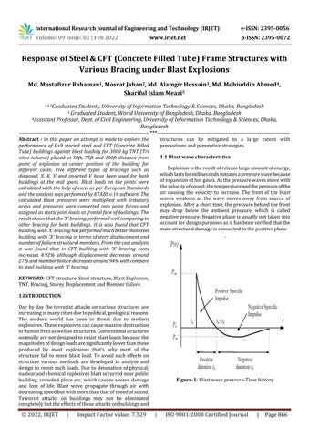
Figure Blastwavepressure Timehistory
1.1 Blast wave characteristics Explosionistheresultofreleaselargeamountofenergy, mainaccountnegativemayexplosion.wavesairtheofwhichlastsformillisecondsinitiatesapressurewavebecauseexpansionofhotgases.Asthepressurewavesmovewithvelocityofsound,thetemperatureandthepressureofthecausingthevelocitytoincrease.ThefrontoftheblastweakensasthewavemovesawayfromsourceofAfterashorttime,thepressurebehindthefrontdropbelowtheambientpressure,whichiscalledpressureNegativephaseisusuallynottakenintofordesignpurposesasithasbeenverifiedthatthestructuraldamageisconnectedtothepositivephase

International Research Journal of Engineering and Technology (IRJET) e ISSN: 2395 0056 Volume: 09 Issue: 02 | Feb 2022 www.irjet.net p ISSN: 2395 0072 © 2022, IRJET | Impact Factor value: 7.529 | ISO 9001:2008 Certified

1:
Journal | Page866
10000
1.3
inch. • Concrete area 221 Square inch (ForFilledSteelTube) • Beam size 10 inch X 18 inch (I Section), Steelarea
200 Large sizedcar 300 Pick uptruck 1400 Van 3000 Truck 5000 Truck
Squareinch • Bracing size 6 inch X 8 inch (Steel Tee), Steelarea
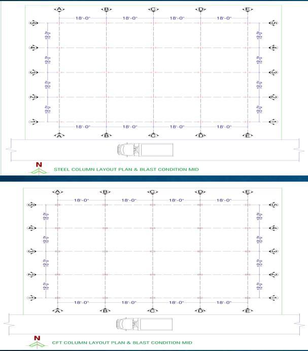
inch. Assignedload: • Liveload 40psf • Partitionwallload 45psf • Floorfinish 20psf • Lineload 400lb/ft Forblastloadingexplosiveweightkeptunchangedandthe cases.explosivewaskeptatcenterpositionofthebuildingforevery
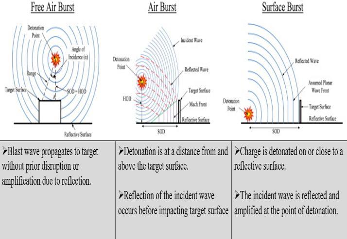
International Research Journal of Engineering and Technology (IRJET) e ISSN: 2395 0056 Volume: 09 Issue: 02 | Feb 2022 www.irjet.net p ISSN: 2395 0072 © 2022, IRJET | Impact Factor value: 7.529 | ISO 9001:2008 Certified Journal | Page867 1.2 Explosion and blast loading types Therearethreetypesofblastloadingwhichareknownas freeairburst,airburstandsurfaceburst. Figure 2:Blastwavetypes
detonationair.burningreleasedenergyisexplosivesweightexplosivesdirecteddevice.vehicleaccountTheweightofanexplosiveisusuallyestimatedbytakingintoarelevantattackscenario,whichwouldinvolveaborneorapersonnelborneimprovisedexplosiveClearly,thelargertheusedvehiclethatcouldbetowardsastructure,thelargertheweightoftheitcouldcarryleadingtohigherequivalentTNTvalues.Intable2anestimateofthequantityofthatcouldbetransportedbyvariousvehicletypespresented.Approximatelyonethirdofthetotalchemicaloftheexplosiveisreleasedbydetonation.TherestisataslowerrateasheatofcombustionthroughoftheexplosiveproductsmixwiththesurroundingTable1providesestimatesoftheproducedheatofofsomecommonexplosives.Table1:IndicativevaluesofheatofdetonationofcommonexplosivesNameofexplosiveHeatofdetonation(Mj/kg)TNT4.104.55C45.86RDX5.136.19PETN6.69PENTOLITE50/505.86NITROGLYCERIN6.3NITROMETHANE6.4NITROCELLULOSE10.6AMON.NIT.(AN)1.59
Table2:Upperlimitofchargeweightpermeansof transportation Carrier weight SizedCar withtrailer 2. Methodology In the present study ten storey steel and CFT frame structureshavebeenanalyzedforexplosiveloadof3000kg fromTNT(Trinitrotoluene)placedat50ft,75ftand100ftdistancepointofexplosion. of ft. 19.15Square 9.83 3.44Square
• Columnsize 20 inchX12inch. • Steelarea
Modeldetails: • Plandimensionof 72 ftX72ftwasmodeled inETABS. • Number
Explosive type and weight
Explosive
spans4ineachdirection,Span length18
(kg) Suitcase 10 Medium
accordingfollowingtoForcheckingthecapacityofastructureorstructuralelementwithstandtheeffectofanextraordinaryevent,thegravityloadcombinationhasbeenconsideredtoASCE710. Planofthe
(0.9 or 1.2) DL + Aĸ + 0.5LL Here, Ak = the load or load effect resulting from extraordinaryeventA(likeexplosionorblasting) Figure-2:
|
buildingmodels
Volume: 09 Issue: 02 | Feb 2022 www.irjet.net p ISSN: 2395 0072 © 2022, IRJET Impact Factor value: 7.529 | 9001:2008
Casesareasfollows:
Certified Journal | Page868
ISO
International Research Journal of Engineering and Technology (IRJET) e ISSN: 2395 0056
Case1:ResponseofSteel buildingandCFTbuildingunder blastloadwith‘Diagonal’bracinginmidspanwithstandoff distanceR=50ft,75ft&100ftrespectively.
Case3:ResponseofSteel buildingandCFTbuildingunder blastloadwith‘InvertedV’bracinginmidspanwithstandoff distanceR=50ft,75ft&100ftrespectively.
Case4:ResponseofSteel buildingandCFTbuildingunder blastloadwith‘K’bracinginmidspanwithstandoffdistance R=50ft,75ft&100ftrespectively.
Case5:ResponseofSteel buildingandCFTbuildingunder blastloadwith‘X’bracinginmidspanwithstandoffdistance R=50ft,75ft&100ftrespectively.

Case2:Response ofSteel buildingandCFTbuildingunder blastloadwith‘V’bracinginmidspanwithstandoffdistance R=50ft,75ft&100ftrespectively.
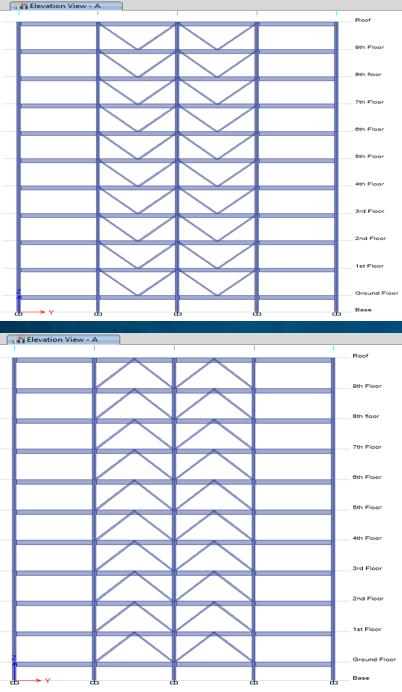
International Research Journal of Engineering and Technology (IRJET) e ISSN: 2395 0056 Volume: 09 Issue: 02 | Feb 2022 www.irjet.net p ISSN: 2395 0072 © 2022, IRJET | Impact Factor value: 7.529 | ISO 9001:2008 Certified Journal | Page869 Figure 3:Elevationofthebuildingwith‘V’bracing, ‘InvertedV’bracing,‘K’bracing,‘Diagonal’bracingand‘X’ bracing Figure 4:3Dviewofthebuildingmodelandblastload assigninthebuilding
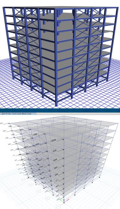
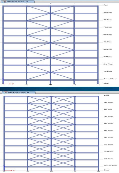
Figure 7:Displacementcomparisonforsteelbuildingsdue to50&75ftstand offdistance.
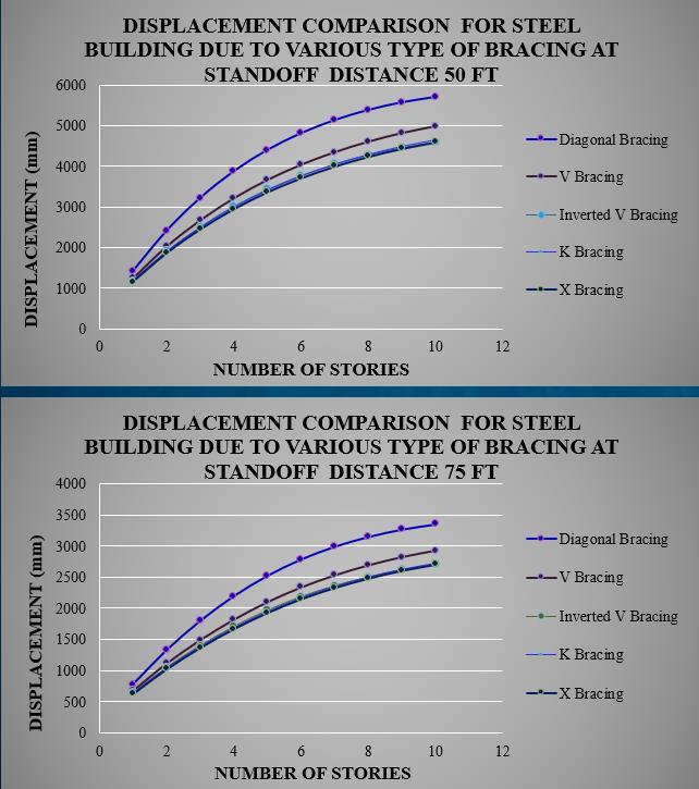

Figure 5:DisplacementcomparisonforCFTbuildingsdue to50&75ftstand offdistance. FromtheFigure 5,itcanbeseenthatatR=50ft,maximum displacementoccurswith‘Diagonal’bracinginCFTbuilding and the ‘X’ bracing performs 37% better than ‘Diagonal’ bracingandforR=75ft,maximumdisplacementoccurswith ‘Diagonal’bracingandthe‘X’bracingperforms37%better than‘Diagonal’bracing.
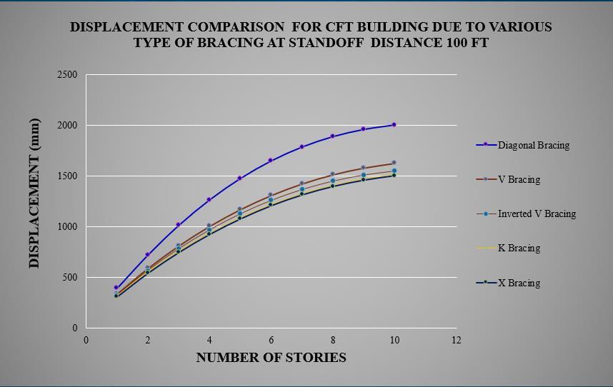
Figure-6:DisplacementcomparisonforCFTbuildingsdue to100ftstand offdistance.
International Research Journal of Engineering and Technology (IRJET) e ISSN: 2395 0056 Volume: 09 Issue: 02 | Feb 2022 www.irjet.net p ISSN: 2395 0072 © 2022, IRJET | Impact Factor value: 7.529 | ISO 9001:2008 Certified Journal | Page870 3. Analysis Result & Discussion
From Figure 7 it can be saidthat at R=50 ft, maximum displacementoccurswith‘Diagonal’bracinginSteelbuilding and the ‘X’ bracing performs 32% better than ‘Diagonal’ bracingandforR=75ft,maximumdisplacementoccurswith
Figure 6 shows that at R=100 ft, maximum displacement occurswith‘Diagonal’bracingandthe‘X’bracingperforms 37%betterthan‘Diagonal’bracing.
Figure 8showsthatforR=100ft,maximumdisplacement occurswith‘Diagonal’bracingandthe‘X’bracingperforms 31%betterthan‘Diagonal’bracing.
Figure 10:DisplacementcomparisonbetweenCFTand SteelframebuildingforXbracingatR=100ft
Figure 9:DisplacementcomparisonbetweenCFTand SteelframebuildingforXbracingatR=50ftand75ft
Figure 8:Displacementcomparisonforsteelbuildingsdue to100ftstand offdistance.
Figure 10showsthatatR=100ft,thedisplacementhas decreased35%for‘X’bracinginCFTbuildingcomparingto Steelbuilding.
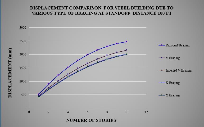
Figure 9showsthatsteelbuildinghasshownmaximum storeydisplacementcomparingtoCFTbuilding.AtR=50ft, thedisplacementhasdecreased35%for‘X’bracinginCFT buildingcomparingtoSteelbuilding.Ontheotherhand,the displacement has decreased 35% for ‘X’ bracing in CFT buildingatR=75ft,comparingtosteelbuilding.
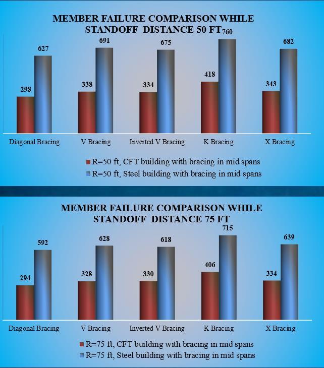
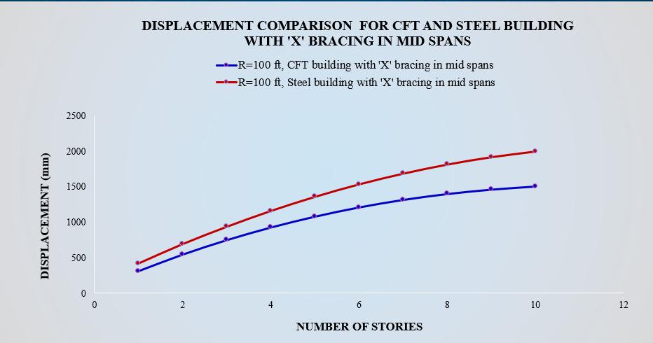
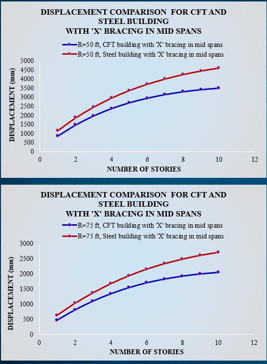
Figure 11:Structuralmembersfailurecomparison betweenCFTandSteelbuildingatR=50ftand75ft
International Research Journal of Engineering and Technology (IRJET) e ISSN: 2395 0056 Volume: 09 Issue: 02 | Feb 2022 www.irjet.net p ISSN: 2395 0072 © 2022, IRJET | Impact Factor value: 7.529 | ISO 9001:2008 Certified Journal | Page871 ‘Diagonal’bracingandthe‘X’bracingperforms31%better than‘Diagonal’bracing.
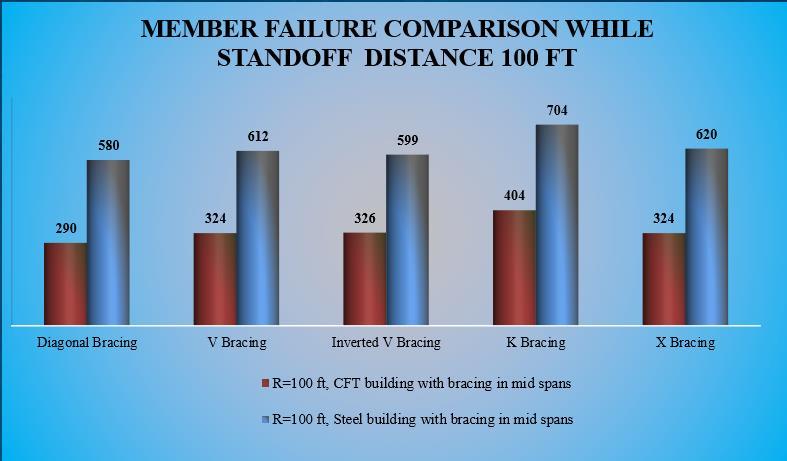
Figure 12:Structuralmembersfailurecomparison betweenCFTandSteelbuildingatR=100ft
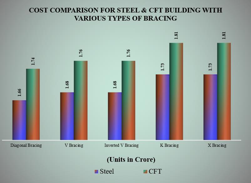
Figure 13:CostcomparisonbetweenCFTandsteel building
As the standoff distance decrease the blast load increases which results higher displacement and failure members have increased drastically in the bothsteelandcompositestructures. At 100 ft standoff distance and with ‘X’ bracing therewerelessmemberfailedduetoblastloading forCFTbuilding. The response of the buildings depends on the standoff distance and the stability of the building increasesasthestandoffdistanceincrease.
Figure 13 shows that from cost analysis it can be concluded that in CFT building with ‘X’ bracing costs increases4.92%.Wheredisplacementdecreases28%,28% &29%andmemberfailuredecreases99%,91%&91%for standoff separation 50ft, 75ft & 100ft respectively with comparetosteelbuildingwith‘X’bracing.
Magnitude of blast load increases as source of explosionclosetostructureanddecreasesassource movesaway.
From the above Figure 11 it can be seen that at 50 ft
4. CONCLUSIONS Fromtheabove results wecanconcludethatCFT building with ‘X’ bracing at mid spans has performed much better than steel buildings in termsofstoreydisplacementandnumberoffailure membersatleaststandoffseparation.
International Research Journal of Engineering and Technology (IRJET) e ISSN: 2395 0056 Volume: 09 Issue: 02 | Feb 2022 www.irjet.net p ISSN: 2395 0072 © 2022, IRJET | Impact Factor value: 7.529 | ISO 9001:2008 Certified Journal | Page872
Figure 12 shows that, the structural members of steel buildingshavefailedmorethantheCFTbuildingswhilethe buildingexplosiveinmiddlepositionat100ftexplosivedistance.CFTperform34%betterthansteelbuilding
betterinfailurperformhaveexplosivedistance,thestructuralmembersofsteelbuildingsfailedmorethantheCFTbuildings.CFTbuilding40%betterthansteelbuildinginaspectsofmembere.Also,at75ftexplosivedistancethebuildingsbehavethesamemanner.At75ftCFTbuildingperform35%thansteelbuilding.
[15] Smart bombs, dumb targeting? by William M. Arkin, Volume 56,No 03,pp.46 53,DOI:10.2968/056003011
BIOGRAPHIES Md. MostafizurRahamanwasborn in 1996 in Pabna, Bangladesh. A skilled structuralandinteriordesigner.Hehas completed his Diploma in Civil Engineering as well Bachelor in Civil Engineeringin2021.Hewasawarded from Inter University AutoCAD draft Mosratcompetitionjahan was born in 1996 in Tangail, Bangladesh. She has depth knowledge in Structural Engineering and has been involved in many government projects. She holds outstanding academic records She completedherDiplomain2015aswell as Bachelor in Civil Engineering from UniversityofInformationTechnology andSciencesin2021. Md.AlamgirHossainhascompletedhis Bachelor in Civil Engineering from World University of Bangladesh in 2018. He is currently working in Matarbari Ultra Super Critical Coal FiredPowerPlantasaSiteEngineer. Mr.Md.MohiuddinAhmed graduated in Civil Engineering in 2013. At the beginning of his career, he got experienceindesignandconstruction of earthquake resilient high rise buildings in different parts of Bangladesh. He has more than 20 Research Publications including publication in Elsevier Conference Proceeding


[13] Blasteffectsonstructures:ACriticalreview,Journalof Xi’anUniversityofArchitectureandTechnology
Considering the parameters such as storey displacement,failuremembersandcostanalysisit can be recommended that CFT frame structures withXbracingmaybecomeasolutionformaking explosionresistantstructures. Advancedcompositesasblastabsorbingmaterials can be introduced such as ceramic/composite armor, fiber composites, foams, magneto rheological (MR) fluids and porous materialsare typicalhighenergyabsorbingmaterials.
[12] Response of RC structure exposed to explosion, International Journal of Science Engineering and Technology,(Volome 04,issue 04)Dr.AbhaySharma, MuhammedHasil
5. Recommendation
International Research Journal of Engineering and Technology (IRJET) e ISSN: 2395 0056 Volume: 09 Issue: 02 | Feb 2022 www.irjet.net p ISSN: 2395 0072 © 2022, IRJET | Impact Factor value: 7.529 | ISO 9001:2008 Certified Journal | Page873
REFERENCES [1] Responseofgridslabmulti storeybuildingssubjected toblastload(2021),IRJET(volume8,issue2)Sandhya G.andDr.SrishailaJ.M. [2] Comparativestudyofblastloadondifferentbuildings (2020),IRJET(volume7,issue7)AkshayGaikwad,j.P. Patankar [3] Explosive violence monitor 2020, AOAV (Action on ArmedViolence)JenniferDathan [4] Dynamic analysis of a building for blast loading at variouslocationsinETABS(July 2019),IJITEE(Volume 8,issue 9,ISSN:2278 3075)SanjeevKumar&Simranjit Singh [5] StudyofconcretedestructiontechniquesusingTNTand C4 to optimize the power of explosives (2018), IJAER (Volume 13, No 02, ISSN: 0973 4562, pp.1101 1108) MadeJiwaAstika,NengahPutra,PutuYogiandOkolS Suharyo [6] AnalysisofblastresistantRCCstructures(November 2017),IRJET(Volume 4,issue 11,e ISSN:2395 0056,p ISSN:2395 0072)SanaN.Kazi,P.V.Muley [7] Mannersofperformingterroristattack2017,(Volume XXIII, No 01, DOI: 10.1515/kbo 2017 0004) Tomasz BAK [8] Analysis of blast loaded structures (January 2008), publication no 299537217, Lucia Figuli, Kamil Boc, VladimirKavicky&DagnarVidrikova
Retrofittingofexistingstructurescanbeasolution towithstandtheeffectsofexplosiveloads.
[9] Blast loading and blast effects on structures and overview(January2007),EJSESpecialissue:loadingon structures,T.Ngo,P.Mendis,A.GuptaandJ.Ramsay [10] Risk management series Primer for design of commercial buildings to mitigate terrorist attacks (December 2003), Federal Emergency Management Agency(FEMA) 427 [11] ASCE 07,minimumdesignloadsforbuildingsandother structures, structural engineeringinstitute,ASCE July,2002.
[14] (Volume XII, issue VI, ISSN: 1006 7930) Mirza ObaidullahBaig&RishabhJoshi
SharifulIslamwasbornin1996infeni, Bnagladesh. He is skilled at construction management and structural design He has completed hisDiplomainArchitecture&Interior Design Engineering in 2016 and Bachelor in Civil Engineering from UniversityofInformationTechnology andSciencesin2021.Hewasawarded from GPH Ispat & Prothom Alo StructuralEngineeringCompetition

Certified Journal | Page874
|
International Research Journal of Engineering and Technology (IRJET) e ISSN: 2395 0056 Volume: 09 Issue: 02 | Feb 2022 www.irjet.net p ISSN: 2395 0072 2022, IRJET Impact Factor value: 7.529 ISO 9001:2008
©
|