International Research Journal of Engineering and Technology (IRJET)
e-ISSN: 2395-0056
Volume: 09 Issue: 02 | Feb 2022
p-ISSN: 2395-0072
www.irjet.net
A Review of Tank Type for Bus Reactor [Bell Vs Conventional(T-Type)] Pritam Jash1, Rahul Dube2 1Assistant.General
Manger (Elec. Design and Engineering), Larsen & Tourbo- Sargent & Lundy Ltd, AT: Vadodara Gujarat. 2Sr.Manager (Electrical), C.Eng.(I), Larsen & Toubro Ltd, AT: Vadodara, Member of IEI ---------------------------------------------------------------------***---------------------------------------------------------------------Abstract -In this study, a comprehensive review on selection of tank type for Bus reactor and its possible aspects which influence the design criticality.
2.1 Conventional tank
Key Words: Bus reactor, Transformer, tank,Bell
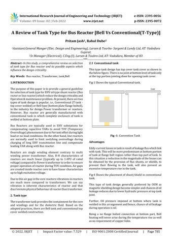
This type tank design has top cover tank cover as shown in the below figure. There is no joint at bottom level of tank only at the top portion jointing done for opening tank cover.
1.INTRODUCTION
Fig:1 Shows the typical Conventional tank.
The purpose of this paper is to provide a general guideline for selection of tank type for EHV oil type shunt reactor (Bus rector or line reactor) which reduce the design criticality and Operation & maintenance problem. At present, there are two types of tank design is popular, i.e., Conventional (T tank top cover welded) or Bell type (bottom plate flange bolted), in the industry for design Power transformer or reactors. However, Bus reactor are generally manufactured with conventional tank in which complete enclosure of tank is welded at bottom plate. Bus Reactors are typically used in EHV substations for compensating capacitive VARs to avoid TOV (Temporary Overvoltage) phenomenon due to Ferranti effect during light load or no-load conditions. On the other hand, line reactors are normally used to limit switching overvoltage during charging of long EHV transmission line and compensate leading VAR along with Bus reactor.
Fig -1: Convention Tank Advantages Eddy-current losses in tank is result of leakage flux which link with tank. This will be more predominant at bottom portion of tank at flange bolt region rather than top part of tank. In this situation a reduction in the magnitude of the losses can be obtained by the provision of flux shunts, or shields, to prevent their flowing in the tank, will also prevent an excessive temperature rise in the tank.
Reactors are single winding element contrary to multi winding power transformer. Also, B-H characteristics of reactors are much linear (typically up to 1.4PU of rated voltage) compared to Power transformer to order to ensure proper operation of reactor during TOV condition. Air gaps are created inside reactor core to have linear characterizes up to high excitation voltage.
Fig:4 Shows the placement of shunt/shield in conventional tank.
Due to this air gap in the core reactors vibrations in reactors are much more compared to transformers. We can say vibration is inherent characteristics of reactor and that discriminate physical behaviour of reactor than transformer.
This type of tank design generally preferred by OEM as magnetic shielding design become simpler and chances of oil leakage reduces due to lower hydraulic pressure at top tank joint.
2. Tank type
Further, Oil pressure imposed at bottom where tank is welded in this arraignment and hence, chance of oil leakage during operation is nil.
The transformer tank provides the containment for the core and windings and for the dielectric fluid. Based on the adopted practices, there are Bell tank and conventional top cover welded construction.
© 2022, IRJET
|
Impact Factor value: 7.529
Being a no flange bolted connection at bottom part, Bolt heating will never arise during the temperature rise as well as no requirement of copper links.
|
ISO 9001:2008 Certified Journal
|
Page 785