Sachin Kumar Sharma1, Dr. Anupam Bhatnagar2
International Research Journal of Engineering and Technology (IRJET) e ISSN: 2395 0056 Volume: 09 Issue: 02 | Feb 2022 www.irjet.net p ISSN: 2395 0072 © 2022, IRJET | Impact Factor value: 7.529 | ISO 9001:2008
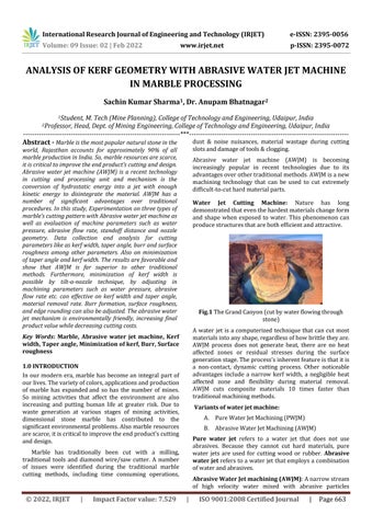
Fig.1
A water jet is a computerized technique that can cut most materialsintoanyshape,regardlessofhowbrittletheyare.
A. PureWaterJetMachining(PWJM)
B. AbrasiveWaterJetMachining(AWJM)
Pure water jet refers to a water jet that does not use abrasives. Because they cannot cut hard materials, pure water jets are used for cutting wood or rubber. Abrasive water jet referstoawaterjetthatemploysacombination ofwaterandabrasives.
Water Jet Cutting Machine: Nature has long demonstratedthateventhehardestmaterialschangeform and shape when exposed to water. This phenomenon can producestructuresthatarebothefficientandattractive.
ANALYSIS OF KERF GEOMETRY WITH ABRASIVE WATER JET MACHINE IN MARBLE PROCESSING
In our modern era, marble has become an integral part of ourlives.Thevarietyofcolors,applicationsandproduction of marble has expandedand so has the number of mines. So mining activities that affect the environment are also increasing and putting human life at greater risk. Due to waste generation at various stages of mining activities, dimensional stone marble has contributed to the significantenvironmentalproblems.Alsomarbleresources arescarce,itiscriticaltoimprovetheendproduct'scutting andMarbledesign. has traditionally been cut with a milling, traditional tools and diamond wire/saw cutter. A number of issues were identified during the traditional marble cutting methods, including time consuming operations, dust & noise nuisances, material wastage during cutting slotsanddamageoftools&clogging.
1Student, M. Tech (Mine Planning), College of Technology and Engineering, Udaipur, India
Certified Journal | Page663
2Professor, Head, Dept. of Mining Engineering, College of Technology and Engineering, Udaipur, India ***
TheGrandCanyon(cutbywaterflowingthrough stone)
Abrasive water jet machine (AWJM) is becoming increasingly popular in recent technologies due to its advantagesoverothertraditionalmethods.AWJMisanew machining technology that can be used to cut extremely difficult to cuthardmaterialparts.
Variants of water jet machine:
Abrasive Water Jet machining (AWJM):Anarrowstream of high velocity water mixed with abrasive particles
AWJM process does not generate heat, there are no heat affected zones or residual stresses during the surface generationstage.Theprocess'sinherentfeatureisthatitis a non contact, dynamic cutting process. Other noticeable advantages include a narrow kerf width, a negligible heat affected zone and flexibility during material removal.
Key Words: Marble, Abrasive water jet machine, Kerf width, Taper angle, Minimization of kerf, Burr, Surface 1.roughness0INTRODUCTION
AWJM cuts composite materials 10 times faster than traditionalmachiningmethods.
Abstract Marble isthe mostpopular naturalstone inthe world, Rajasthan accounts for approximately 90% of all marble production inIndia. So, marble resources are scarce, it is critical to improve the end product’s cutting and design. Abrasive water jet machine (AWJM) is a recent technology in cutting and processing unit and mechanism is the conversion of hydrostatic energy into a jet with enough kinetic energy to disintegrate the material. AWJM has a number of significant advantages over traditional procedures. In this study, Experimentation on three types of marble’s cutting pattern with Abrasive water jet machine as well as evaluation of machine parameters such as water pressure, abrasive flow rate, standoff distance and nozzle geometry. Data collection and analysis for cutting parameters like as kerf width, taper angle, burr and surface roughness among other parameters. Also on minimization of taper angle and kerf width. The results are favorable and show that AWJM is far superior to other traditional methods Furthermore, minimization of kerf width is possible by tilt a nozzle technique, by adjusting in machining parameters such as water pressure, abrasive flow rate etc. can effective on kerf width and taper angle, material removal rate. Burr formation, surface roughness, and edge rounding canalso be adjusted. The abrasive water jet mechanism is environmentally friendly, increasing final productvaluewhiledecreasingcuttingcosts.

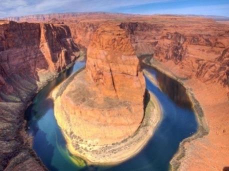
Table 2.3 Specificationofflowmach2waterjetmachine Cuttingtable 5000x3000mm Power 3850Bars Weight 8500kg Workedhours 2500hours MaxOperatingPressure 60,000PSI AbrasiveHopperCapacity 500Lbs. Pump Intensifier pump (60,000 psi) Nozzle tungsten carbidematerial Abrasiveflowsystem Gravityfeedtypewithgas propulsionsystem
The materials used for present study are (a) Makrana generic white Marble (b) Rajnagar marble (c) Keshariyaji green marble. The marble is a brittle material and has the various applications as a building/construction material. The dimensions of these marbles were 300mm × 77mm × 22.5 mm. The Chemical composition, Mechanical and physical properties of all rock are shown in Table 3.1 and 3.2. Table 2.1 ChemicalCompositionMarblerocktypetested Table 2.2 Mechanicalandphysicalpropertiesoftested marble
There are number of influencing cutting parameters who affect kerf width, taper angle, depth of cut and material removal rate but large no. of cuttings runs are not viable and costly procedure. So, we take 10 cutting runs with variation of parameters like Water pressure and abrasive flowrateonthreemarbletypes.
Intotal,10cuttingrunswereperformed,9withparameter changes and one for surface roughness for each marble type. The output response parameter kerf top width, kerf bottom width and kerf taper angle has been studied in order to optimize the process parameter cutting for three marble types. Input parameters were collected using the AWJM'sPCcontroldevice,whileoutputparameterssuchas kerfwidthandtaperangle,aswellasmaterialdimensions,
Elements Weight % MarblewhitegenericMakrana marbleRajnagar greenKeshariyajimarble Silica(SiO2) 20 25% 16 25% 28 32% Lime(CaO) 38 42% 30 33% 16 30% Loss IgnitionOn(LOI) 30 32% 36 44% 20 30% OtherOxides likeNa.Mg 1.5to2.5% 1 7.5% 20 25% Alumina(Al2O3) 2 4% 2 4% 1 2% Property Value MarblegenericMakranawhite marbleRajnagar marblegreenKeshariyaji Hardness 3to4onMoh's Scale 3to4 Moh'sonScale 3to4 Moh'sonScale Density 2.5to Kg/m³2.65 2.80to2.90 Kg/cm2 2.66 2.70Kg/cmto2 AbsorptionWater Less 1%(0.04)than Less 1%(0.06)than Less 1%(0.07)than StrengthCompressive 1800to2100 Kg/cm² 1000to Kg/cm15002 1900to3000 Kg/cm2 color White Whitewith bands Whitewith bands Porosity Quitelow Quitelow Quitelow
produces a low cost, environmentally friendly product withahighmaterialremovalrate.AWJMtypicallyemploys a variety of abrasives such as garnet, olivine, aluminum oxide (Al2O3), silicon carbide (SiC) and others. The water actsasanacceleratorfortheabrasiveparticles,strikingthe material at an impact speed of 800 m/s and removing it precisely.
International Research Journal of Engineering and Technology (IRJET) e ISSN: 2395 0056 Volume: 09 Issue: 02 | Feb 2022 www.irjet.net p ISSN: 2395 0072 © 2022, IRJET | Impact Factor value: 7.529 | ISO 9001:2008 Certified Journal | Page664
2.1Experimentation on marble cutting for kerf width and taper angle
Table 2.4 Constantparametersforexperiment Abrasivematerial Garnet Abrasivemeshsize #80 Orificediameter 0.4mm Nozzlediameter 0.8mm Nozzlelength 101.6mm Jetimpingementangle 90° Stand offdistance 5mm Cuttinglengtheachrun 42mm Mixingtube 1.0160mm
2.1.1 Equipment: Cutting equipment was utilized to cut the sample flow mach 2 abrasive water jet and machine’s dimension 5000 × 4800 × 3000mm with single head. Machine can control either manual or automatic after given cutting command. Water jet machine attached with all other necessary systems like Pump, gas propulsion system, abrasive storage, abrasive feed system, electricity system,computercontrolsystemandcatcher.
Fig. 2.1 Flowmach2waterjetcuttingmachine
2.0 EXPERIMENTAL WORK
weremeasuredusinga"digitalverniercaliper".Equation1 is used to calculate the kerf taper angle the taper angle is obtainedusingtheformulabelow.
B. Standoff distance: Thestandoffdistanceissetto 5 cm as a constant; increasing the standoff distance will increase the kerf widths. The nozzle's X and Y axes are aligned to the sample, whereasthez axisisperpendiculartothenozzle.
C. Abrasive parameters: By experimenting with a range of abrasive flow rates, the required abrasive flow rate was determined. Because the qualityoftheabrasiveshasanimpactonthekerf width,weusehigh gradeGarnet#80meshsize.
2.3 Tilting the cutting head
2.4 Experiment for surface roughness
By computer control, command is instructed to tilt the nozzleslightlytothescrapingsidetoreducekerfwidth.
2.6 Experimentation for wear nozzle
θ = tan 1 ( ) ….Eq.1 Where:θ = kerf taper angle (TE/KA), t = thickness of sample tan 1=archtan Wt/Tkw =topkerfwidth, Wb/Bkw =bottomkerfwidth
Burrswerenotedonthejetexitside(bottomkerf)onsome of the cuts due to material deformation. Burr is often developed near the kerf's bottom border. For the purpose of the experiment, take note of the burr after each cutting ofthesample.
To determine the nozzle wear rate, simply compare the weight of the nozzle before and after the experiment, as well as the nozzle weight loss rate, also known as the nozzlelifeindicator.
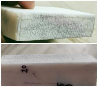
For surface roughness, we cut the sample into two parts, photograph the surface roughnessand compare it to the surfaceroughnessscale(seefigure3.7). 45000psi(WP)andhighAFR
3.0 RESULTS
3.1 Quantitative Results of Minimization of Taper Angle and Kerf Width: As we all know, kerf width and taperangleareinextricablylinked;therefore,weprecisely measuredusingdigitalverniercalliperanddiscoveredthe result.
2.5 Experimentation for burr
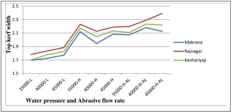
3.1.1 Kerf width as a function of water pressure and abrasive flow rate: As shown in the graphs, the top kerf width increases as water pressure increases while the abrasive flow rate remains constant as low or high. no.Run WP(psi) (g/min)AFR Kerf width(mm) for rock sample (a) Kerfwidth(mm)forrocksample(b) Kerfwidth(mm)forrocksample(c) Tkw/Wt Bkw/Wb TE(°) Tkw/Wt Bkw/Wb TE(°) Tkw/Wt Bkw/Wb TE(°) 1. 35000 Low 1.695 NC 1.783 NC 1.702 NC 2. 40000 Low 1.726 1.291 0.553 1.836 1.392 0.561 1.780 1.311 0.595 3. 45000 Low 1.773 1.522 0.319 1.885 1.689 0.253 1.825 1.579 0.309 4. 35000 High 2.121 1.806 0.401 2.229 1.969 0.331 2.173 1.869 0.383 5. 40000 High 1.946 1.606 0.432 2.126 1.801 0.412 2.046 1.713 0.423 6. 45000 High 2.083 1.453 0.802 2.188 1.623 0.716 2.131 1.578 0.698 7. 35000(Al) High 2.073 1.291 0.995 2.197 1.445 0.957 2.108 1.504 0.768 8. 40000(Al) High 2.181 1.451 0.929 2.288 1.624 0.842 2.233 1.536 0.859 9. 45000(Al) High 2.126 1.036 1.387 2.391 1.167 1.387 2.218 1.093 1.432
Table 2.5 Datasummaryfortopandbottomkerfwidthandtaperangleforthreerocks
A. Speed/Water pressure: Wecanfindtheoptimal speed for minimum kerf widths by gradually increasing the speed. It began with a water jet pressureof35000to45000psi.
Fig. 2.2 Surfaceroughness
International Research Journal of Engineering and Technology (IRJET) e ISSN: 2395 0056 Volume: 09 Issue: 02 | Feb 2022 www.irjet.net p ISSN: 2395 0072 © 2022, IRJET | Impact Factor value: 7.529 | ISO 9001:2008 Certified Journal | Page665
D. Thickness and hardness of material: Both factors have an impact on kerf widths. Kerf widthsriseasthicknessandhardnessincrease.
Weexperimentedwiththefollowingstrategiestominimize bothtopandbottomkerfwidths: 2.2.1 Controlling input parameters of water jet
2.2 Method for minimizing kerf width
3.1.2 Taper angle function with water pressure and abrasive flow rate
Through experimentations and knowledge gained during experiments, we discovered some of the techniques for minimizingkerfwidthandtaperangle.Theseare:
e) Quality of abrasive used: By combining an abrasive with a supersonic water stream, water jetscut.Atthesamecuttingspeed,ahigher quality
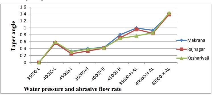
Fig.3.3 Waterpressuresandabrasiveflowratevs.taper angle 3.2 Minimization of kerf width and taper angle
a) Speed of water jet cutting: Speed of water jet directly affect kerf width and taper angle. By controlling the speed of the water jet, we can minimizeboththekerfwidthandthetaperangle. High speeds are used to cut thin materials, whereas low speeds are used to cut thick materials. Thin materials may taper more than thickermaterials.Tapercanbeeliminatedonlyby slowing down the cut speed if a water jet with taper compensation is not provided. V shaped taperisproducedbyhighercutspeeds,whileless taper is produced by lower cut rates. Cut speeds thataretooslowcancausereversetaper.
Page666
International Research Journal of Engineering and Technology (IRJET) e ISSN: 2395 0056 Volume: 09 Issue: 02 | Feb 2022 www.irjet.net p ISSN: 2395 0072 © 2022, IRJET | Impact Factor value: 7.529 | ISO 9001:2008 Certified |
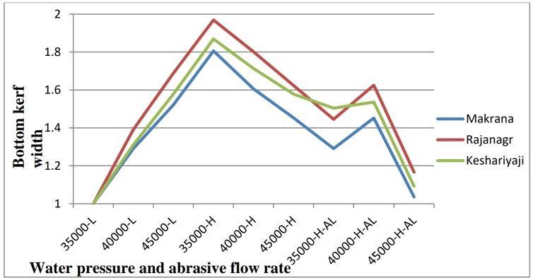
Fig 3.1 Waterpressureandabrasiveflowratevs.topkerf width Fig.3.2 Waterpressureandabrasiveflowratevs.bottom kerfwidths
The taper angle is defined as the difference between the top kerf width (Tkw) and the bottom kerf width (Bkw) and theirarctangentoverhalfofthethickness,soitisentirely dependentonkerfwidth.Asshowninthegraph,aswater pressure rises, the taper angle rises as well, reaching a maximum of nearly 1.2 degree. As well as abrasive flow rateincreasestaperanglealsoincreases.
d) Quality of cutting stream: Lesstaperisproduced by nozzles that are more focused. The cutting stream loses its symmetry and coherence if the orificeandnozzlearewornorbroken.
c) InboththeXandY axisdirections,makesurethe Z axisisperpendiculartothematerial.
Journal
The graph showsthe relationship between kerf widthand abrasive flow rate. As the abrasive flow rate increases, so does the kerf width due to the increased imping rate of particals.
b) Amount of nozzle standoff: The jet stream can spread if the nozzle is too far away from the material,resultingintaperedcutfacesandsevere erosion on the cut's top edge. The less taper you have, the lower you can get the nozzle to the substance.Inmostcases,anozzlestandoffof5cm issufficient.
However, the bottom kerf width initially increases and then decreases while the water pressure continues to increasebecausethewaterpressurerisesto45000psi,the depth of cut and material removal rate increase, resulting inadecreaseinbottomkerfwidth.Becausewaterpressure andabrasiveparticleshavemoretimeandareatoimpinge on the work sample, the top kerf width increases in comparison to the bottom kerf width. Between the three marbletypes tested(a)Makrana generic whitemarble(b) Rajnagarmarble(c)Keshariyajigreenmarble,marbletype (a) has less kerf width in all experiments because the hardness of marble (a) is lower than the hardness of both other marble types. Similarly, marble type (c) has a lower hardnessthanmarbletype(b)asshowningraphs(fig.3.1).
f) Thickness and hardness of material: The thicknessandhardnessofthesamplehaveadirect effect on the kerf width/taper angle; as the thicknessandhardnessoftheworkpieceincrease, sodoesthetaperangle/kerfwidth.
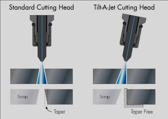
Tilt A JetCuttingHead
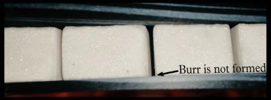
Asresults,ifaburrisproducedinmarblestone,itiseither not formed if it is generated and erased by water and It's alsoimpossibletomeasure(photogrammetricresult).
The following conclusions were reached based on the results:1)
Fig.3.4
g) Tilting the cutting head: Taper angle/kerf width can also be minimized by using an articulated tilting nozzle to tilt the cutting head in the opposite direction of the cutting. Using a predictivemodel todeterminetaperinthekerfat eachsegmentofa cuttingpath,thesystemdirects the nozzle head to tilt in line with the component edge, resulting in taper on the scrap side of the material and square, taper free edges on your product.
4. CONCLUSIONS
Surface roughness increases when water pressure rises, although abrasive flow rate has only a minor impact. Surface roughness or surface striation is influenced by traverse speed. The surface roughness of the sample as determined by the quality factor (Zeng and Kim, 1993) is Q2 (though cut fine). Cutting results for three types of marble are optimized when water pressure is 40000 45000 Psi and the abrasive flow rate is high, resulting in highsurfaceroughness.
3) Experimentresultshowsthatminimizationofkerf width/taper angle are possible by controlling inputparametersandusetilt a nozzletechnique.
4) Experiment result shows that by adjusting machining parameters such as water pressure, stand offdistance,traverserateandabrasiveflow
PARAMETERS pressureWater ↑ distanceStandoff ↑ rateflowAbrasive ↑ Kerf width ↑ ↑ ↑ Taper angle ↓ ↑ # roughnessSurface ↑ ↑ ↓ Materialrateremoval ↑ ↓ ↑ Depth of cut ↑ ↓ ↑
Nozzle life is approximately 12 13 hours and we can increase nozzle life through wear prevention. The approach of using porous lubricated nozzles was developedasasolutiontopreventthenozzlefromwearing out. Toextendnozzlelifeandreducewear,a novelnozzle madeoftungstencarbide basedmaterialhasbeencreated.
3.4 Analysis for Burr
International Research Journal of Engineering and Technology (IRJET) e ISSN: 2395 0056
3 3 Analysis for Surface Roughness
Volume: 09 Issue: 02 | Feb 2022 www.irjet.net p ISSN: 2395 0072 © 2022, IRJET | Impact Factor value: 7.529 | ISO 9001:2008 Certified Journal | Page667
Table 3.1 Comprehensiveresultsofexperiments Where↑=increasing, ↓=decreasing, #=notsignificant
Abrasivewaterjetmachine(AWJM)isfarsuperior to other traditional methods due to numerous advantages and processes such as no dust generated, no heat affect zone (HAZ), no material distortion, easy process and water availability. And flow mach 2 machineused and having better configuration.
Asaresult,nozzleweightsare Weightbeforeexperiment=50gram Weightafterexperiment=49.98gram
Fig.3.5 Burr
3.5 Analysis for Wear of Nozzle
Wear can also be decreased by using soft abrasive materialsorhardmaterialnozzles.
2) In the mining industry, marble is widely used in every industry and (a) Makrana generic white marble (b) Rajnagar marble (c) Keshariyaji green marble as their physicochemical properties are studied and tested all are respectively different featuresandidentity.
abrasive such as crushed garnet cuts more aggressively, resulting in better cut quality and lesstaper.
Special thanks to Siri Maharaja Granites (P) Ltd., Mr. Hari Mohan Sharma, for authorizing and mentoring me in his laboratory to conduct research on an Abrasive water jetmachine.
ACKNOWLEDGEMENT
Ramulu, M., Hashish, M., Kunaporn, S. and Posinasetti, P., 2002. "Abrasive waterjet machiningofaerospace materials",International SAMPE Technical Conference, Vol. 33,, pp. 1340 1354.
International Research Journal of Engineering and Technology (IRJET) e ISSN: 2395 0056 Volume: 09 Issue: 02 | Feb 2022 www.irjet.net p ISSN: 2395 0072 © 2022, IRJET | Impact Factor value: 7.529 | ISO 9001:2008 Certified Journal | Page668
5) The results show that cutting three types of marbleathighwaterpressurewithahighabrasive flowrateproducesbetterresultsintermsofdepth of cut, material removal rate but as well as increases kerf width and surface roughness. Burr and edge rounding is very mi nute or negligible. Thewearofnozzleproblemisseriousconcern.
rate, we can optimize cutting parameters such as depthofcut,materialremovalrate,kerfwidthand surfaceroughness.
Azmir M.A. and Ahsan A.K. 2009. A study of abrasive water jet machining process on glass/epoxy composite laminate, In: journal of materials processing technology 209: pp. 6168 6173.
ÖjmertzC.1994.Aguideto:waterjettechnology. In: department of production engineering universityoftechnology,Gothenburg. Rozario J., Jegaraj J. and Ramesh Babu N. 2007. A soft computing approach for controlling the quality of cut with abrasive water jet cutting system experiencing orifice and focusing tube wear, In: Journal of Materials Processing Technology,185(1 3):pp.217 227. Shanmugam D.K. and Masood S. H. 2009. An investigation on kerf characteristics in abrasive waterjetcuttingoflayered composite,In: journal ofmaterialsprocessingtechnology209:pp.3887 3893. Zeng J. and Kim T.J. 1993. Parameter prediction and cost analysis in abrasive water jet cutting operations. In: 7th American Water Jet Conf., SeattleWashington:pp.175 189. Zeng J., Heines R., and Kim T.J. 1991. Characterization of energy dissipation phenomenon in abrasive waterjet cutting. In: Proceedings of the 6th American Waterjet Conference, Houston, Texas, USA, August, 1999, pp163 177. Kolb M. 2006 “Material processing with high pressure water jet” SV corporate media GmbH, Munich. Chen L. F., Wang J., Lemma E. and Siores E. 2003. Striation formation mechanism on the jet cutting surface, In: Journal of Process Technology, 141: pp.213 218. ShawM.C.1996.Principlesofabrasiveprocessing. In:OxfordUniversitypressinc.Newyork,USA
REFERENCES
Sachin Kumar Sharma Student, M. Tech (Mine Planning), College of Technology and Engineering, Maharana Pratap University of Agriculture and Technology, Udaipur, Rajasthan, India.
BIOGRAPHIES
Dr. Anupam Bhatnagar Professor, Head, Dept. of Mining Engineering, College of Technology and Engineering, Maharana Pratap University of Agriculture and Technology,Udaipur,Rajasthan,India.