6.Structuraldetailingformembers.
. “G+25”
Seismic design for high rise buildings has grown increasingly essential in recent years. For structures of small height subjected to low intensity earthquakes, traditionalmethodsbasedonthefundamentalmodeofthe structure and the distribution of earthquake forces as staticforcesatvariousstoriesmaybesufficient,butasthe numberofstoriesincreases,seismicdesignbecomesmore for a R.C.C building with a G+25 storey frame is being considered. The design is done with structural analysis design software (staad pro). The structure was subjected to vertical as well as horizontal loads. The dead load of structural components such as beams, columns, andslabs,aswellaslivingloads,makeuptheverticalload. The seismic forces make up the horizontal load, hence buildings are constructed for dead load, live load, and seismicload,accordingtoIS1893 2016.Thestructureis constructed as a two dimensional vertical frame that is trial and error assessed for maximum and minimum bending moments and shear forces in accordance with IS 456 2000. The assistance is provided via software availableattheinstitute,whichallowsforthecomputation ofloads,moments,andshearforces.
ABSTRACT
1. Vikrant Trivedi.et.el; (2018): This research compares wind loads in order to determine the design loads of a G+11 structure. The purpose of this investigation is to determine the design loads for a structurethat is exposed to wind loads in a specific area. It is well knowledge that thewindloadinaspecificzonecanbeapproximatedusing a zone factor. The wind load of that zone can then be calculated using the fundamental wind speed and other elements unique to that region. The wind velocity, on the otherhand,isstochasticandtimedependent.Amultistory
This research was carried out with an objective to determine the design loads of a G+25 Multistoried building structure which is an earthquake resistant structure. The purpose of this investigation is to determine the design loads for a structure that will be subjected to seismic loads in a specific area. It is well knowledge that seismic loads can be estimated in a certain zone using a zone factor. The seismic load of that zone can then be calculated depending on the magnitude of the earthquake and other characteristics unique to that region. cost.acceptablestrength,totalstructuraldemandThHowever,Earthquakeloadisstochasticandtimedependent.estructureshouldbeconstructedtomeetthetargetforthedurationofitslife.Themaingoalsofdesignaretocreateastructurethatprovidesresonancewhilemaintainingsafetyintermsofstability,andstructuralintegrity,aswellasserviceabilityintermsofstiffness,longevity,and
2. Determination of criticality and vulnerability in seismic 3.performance.Researchintoseismiccodalprovisions.
LITERATURE SURVEY
ANALYSIS AND DESIGN OF MULTISTORIED EARTHQUAKE RESISTANT BUILDING
Anjum Asfi1 , Vikash Kumar Badal2 , Dr. Alok Singh3 1M.Tech Scholler, CIT Ranchi, Cambridge Institute of Technology, Ranchi. 2,3Assistant Professor, Cambridge Institute of Technology, Ranchi. ***
International Research Journal of Engineering and Technology (IRJET) e ISSN: 2395 0056 Volume: 09 Issue: 02 | Feb 2022 www.irjet.net p-ISSN: 2395-0072 © 2022, IRJET | Impact Factor value: 7.529 | ISO 9001:2008 Certified Journal | Page631
OBJECTIVES The project's major goal is to improve knowledge of multistory RCC building structural design and architectural works. This project teaches us how to examinefielddifficultiesandhowtoarriveatareasonable solution, as well as refresh our knowledge of structural member design. Workingin a real worldsetting improves theoreticalandpracticalknowledge,aswellasconfidence, which will be useful in professional activity in the near Thefuture.following are the precise objectives of the project's work:1.Identification
oftheplan'sstructuralorganization.
INTRODUCTION
Key Words Analysis and Design, Earthquake Resistant, Seismic Load, Stability, Stiffness, Staad Pro.
Arigorous.design
4. Use of Staad Pro to model the building for structural 5.analysis.Componentsaredesignedinsections.

Structural analysis is primarily concerned with determining how a structure behaves when it is subjected to some action. Using the ETABS software, a residential (G+5) multi story building is investigatedforseismicloads.Thelinearstaticanaisdone assuming that the material property is true. These linear static assessments take into account four seismic zones (zoneII,zoneIII,zoneIV,andzoneV),andthebehaviouris evaluated using Type II soil conditions. The reactions of various load combinations and zones, such as bending moment and axial forces, are investigated. The bending moment and axial force are also affected by the T seismic load.
5. Varikuppala Krishna, Chandrashekar.et.al; (2015 StructuralEngineersfacethedifficulttaskofachievingthe mostefficientandcost effectivedesignwhileensuringthat the final design of a building is functional for its intended functionduringitsdesignlife–period.Tprojectis an RCC framed structure with (parking floor +5) upper floors that was assessed and planned using ETABS to account for the lateral loading impacts of wind and earthquake (Extended Three Dimensional Analysis of Building system). ETABS is a software that includes all of the primary analysis engines, such as static, dynamic, Lin, and non & ndash:linear, and it is used to analyse and designstructures.Buildings canberepresentedasperthe arrangementoftmembersoftheprojectinpractisethanks to the features offered in this software modelling stage, and this programme treats beam columns as line members; slabs, Ramps/staircases, and walls as area members. Considering the effects of wind and seismic forces on horizontal loading; In the d of this project, I considerdynamicloadingin addition tostaticloadingand LivloadsasperIScode;andpracticallyalloftheproject's members may be ana and designed as per Indian code using this software, with the members utilising excel sheetsthatIgenerateduringthisphase.
3. Aman.et.al;(2016):
Volume: 09 Issue: 02 | Feb 2022 www.irjet.net p-ISSN: 2395-0072 © 2022, IRJET | Impact Factor value: 7.529 | ISO 9001:2008 Certified Journal | Page632
4. Ms.PriyankaSoni.et.al.;(2016):Ms.PriyankaStudiedon Shear walls are structural systems that protect structures from lateral loads such as wind and earthquakes. These structural systems are made of reinforced concrete, plywood/timber unreinforced masonry, and reinforced masonryatthelocationswherethesesystemsaremadeof reinforcedconcrete,plywoodstaggeredwalls.Thecurrent paperwaswrittenwiththegoalofstudyingandanalyzing numerous researchprojectsinvolvingtheenhancement of shearwandtheirbehaviorwhensubjectedtolateralloads. Shear walls withstand substantial lateral stresses in the lowerhalfofthebuilding,whiletheframesupportslateral loads in the higher portion, making soft storey high rise buildings ideal. In India, similar structures have been created. As in India, the lower floors are utilised for parking and garages, while the top floors are used for residences.
METHODOLOGY
International Research Journal of Engineering and Technology (IRJET) e ISSN: 2395 0056
6. K.RamaRajuetal.,2013;Fortallstructurebehaviourto be determined, site specific lateral loading due to wind or earthquakestresses,aswellasverticalgravityloads,must be taken into account. The amount of structural material required to resist lateral loads increases dramatically as a building's height increases. To securely carry gravity and lateral loads, tall building design entails a conceptual de approximate analysis, preliminary design, and optimization. Strength, serviceability, and human comfort arethedesigncriteria.The structural engineer'sgoal isto comeupwithappropriatestructuralplansthatmeetthese criteria. The limit technique of analysis and design of a 3B+G+40 story reinforced concrete high rise building under wind and seismic loads is given in this work, according to IS rules of practise. Allowable limitations for base shear, roof displacements, inter story drifts, accelerations defined in codes of practise, and other relevant references in literature on the effects of earthquake and wind loads on buildings are verified to ensurethestructure'ssafety.
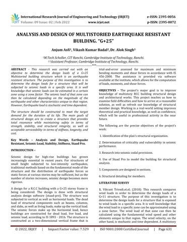
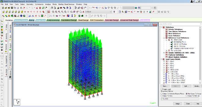
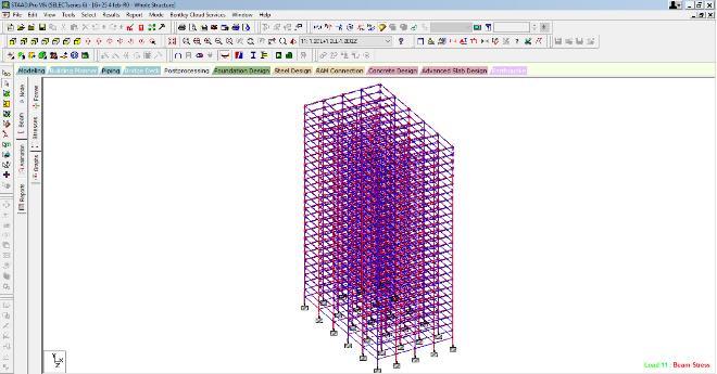
Modelling of Frame: G+25ResidentialBuilding
2. MB Vikram.et.al;(2017):
Thefundamentalgoalofastructural engineer is to build a structure for safe computer technology; structural engineers can handle much larger and more sophisticated structures that are subjected to many types of loading conditions. Previously, the loads acting on the structure were regarded static, but strictly speaking, no structure load is static, with the exception of self weight (dead load). Today, a great variety of application software is accessible in the civil engineering sector. All of these programmes are built on a foundation of superior technology. Finite element analysis, which takes into account the effects of dynamic loads like as wind,earthquakes,andothernaturaldisasters.Anattempt was made in the previous work to investigate the efficacy of particular civil engineering application software. An ongoing project has been chosen for this purpose. This initiative is part of the Gulbarga City's Unity Builders programme.Theproject'snameisBharatPride.
Thisprojectisprimarilysoftware based,anditisessential tounderstandthespecificsofthesesoftware.
building is examined for wind loads using IS code 875 in this study, and the findings are compared between with andwithoutwindload.
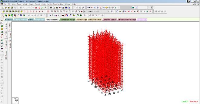
3DRenderedViewofBuilding DiagramforShearforce DiagramforBendingMoment
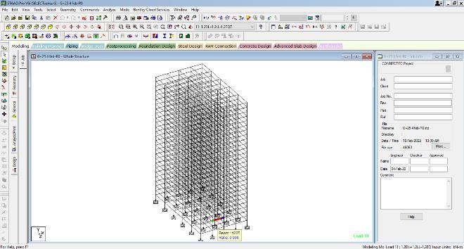
International Research Journal of Engineering and Technology (IRJET) e ISSN: 2395 0056 Volume: 09 Issue: 02 | Feb 2022 www.irjet.net p-ISSN: 2395-0072 © 2022, IRJET | Impact Factor value: 7.529 | ISO 9001:2008 Certified Journal | Page633 ModellingofFrameInStaadPro Loading in Structure: DeadLoad,LiveLoad,and SeismicLoadingLoad.AppliedonBuildingFrame Following Load Combinations are adopted i. 1.5DeadLoad+1.5LiveLoad ii. 1.2DeadLoad+1.2LiveLoad+1.2EQx iii. 1.2DeadLoad+1.2LiveLoad 1.2EQx iv. 1.2DeadLoad+1.2LiveLoad+1.2EQz v. 1.2DeadLoad+1.2LiveLoad 1.2EQz Analysis and Design: Analysis of RCC Framed structure, Analysis for Shear Force and Bending Moments has been doneusingStaadPro. STAAD PRO can determine the amount of reinforcement required for any concrete segment. The programme includes a number of parameters that are designed in accordance with IS: 456. (2000). Flexure, shear, and torsionarealldesignedintobeams.
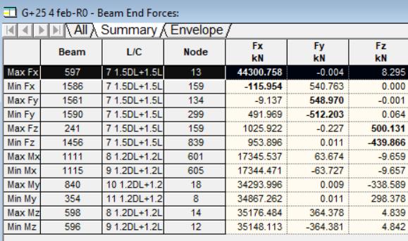
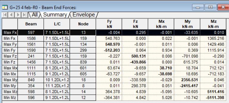
The maximum shear force at X Direction is found at column no 597 Which is located at the basement floor of the building for the combination load having value of 44300.758KN.ThemaximumshearforceatY Directionis foundatbeamno1561WhichislocatedattheNinthfloor of the building for the combination load having value of 548.970 KN. The maximum shear force at Z Direction is found at column no 241 Which is located at the Twenty Fifth floor of the building for the combination load having value of 500131 KN. The maximum bending Moment developed in X Direction is found at column no 1111 Which is located at the Fifth floor of the building for the combination load having value of 38.710 KNm. The maximum bending Moment developed in Y Direction is found at column no 840 Which is located at the basement
Results and Discussion
Future Scope: Staad Pro is used to analyse tall buildings under seismic load.Idiscoveredthatwiththissoftware,thedesignoftall and complex structures can be done with maximum accuracy,andthatwhiledesigning,weshouldaimtolimit the structure's self load by using light weight, environmentally friendly materials such as ACC Block. As highgradeofconcreteisnecessarytoacquirethestrength as well as the compaction of concrete is vital component for which Self Compacting Concrete is suggested to avoid anyformofHoneycombandblowholes.
The safe Size of the Interior and Exterior column from Eleventh Floor level to Fifteenth Floor Level is 1000mm x The750mm.safe
floorofthebuildingforthecombinationloadhavingvalue of 2536.531 KNm. The maximum bending Moment developedinZ Directionisfoundatcolumnno598Which is located at the basement floor of the building for the combinationloadhavingvalueof5111.416KNm.
TheStructuralmembersbeamsandcolumnofthe buildings are are safe in shear, flexure and deflection of horizontal members are within 20mm. The steel provided in the structure is economical andasperISCodes.
Conclusion A multi story residential building with a G+25 storeywas researched, assessed, and designed. It's a G+25 story building withparkingonthegroundfloorandapartments ontheupperlevels.Allofthestructuralcomponentswere designed and detailed using AutoCAD. The analysis and design were conducted using STAAD and conventional criteria. This is the greatest option for both static and dynamic loads. The size of the structural members are calculated, and loads such as dead, live, and seismic loads are applied. Deflection and shear tests are performed on beams, columns, and slabs. The tests turned out to be completely risk free. Both theoretical and practical work hasbeencompleted.
Thesizeofthestructural membersobtainedfrom STAADcanbeusedinconstruction.
size of the beam along X direction is 300mm x 500mm and along Z direction is 350mmx650mm at all levelsofthebuilding.Minimumpercentageofsteelis0.2% and Maximum percentage of steel is 4.0% is used in all Thebeams.safe
Sizeoftheinteriorcolumnatthefoundationlevel is1300mmx1300mm.
International Research Journal of Engineering and Technology (IRJET) e ISSN: 2395 0056 Volume: 09 Issue: 02 | Feb 2022 www.irjet.net p-ISSN: 2395-0072 © 2022, IRJET | Impact Factor value: 7.529 | ISO 9001:2008 Certified Journal | Page634
TableformaximumShearForce TableforMaximumbendingMoments. Using Concrete Grade of M30 and Reinforcement Steel
TheFe550.Safe
ThesafeSizeoftheexteriorcolumnatthefoundationlevel is1200mmx1200mm. The safe Size of the Interior and Exterior column from GroundleveltoFifthFloorLevelis1200mmx1200mm.
The safe Size of the Interior and Exterior column from SixthFloorlevel to Tenth FloorLevel is1000mmx 1000 mm.
Size of the Interior and Exterior column from SixteenthFloorleveltoTwentieth FloorLevelis1000mm x The600mm.safeSize of the Interior and Exterior column from Eleventh Floor level to Fifteenth Floor Level is 750mm x M500mm.inimum percentage of steel is 0.4% and Maximum percentageofsteelis6.0%isusedinallcolumns.
3) IS 875 (Part1, Part2, Part3): 1987, “Code of practice for design loads for building and structures”BureauofIndianStandards,NewDelhi 1989.
6) Aman, Manjunath Nalwadgi, Vishal T, Gajendra Rao, “ Analysis and Design of Multistory Building usingStaadPro”,InternationalresearchJournalOf Engineering and Technology (IRJET), Volume 03, Issue :06 e ISSn: 2395 0056, PISSN:2395 0072, June2016.
8) Ghosh K.S.,Munshi J.A. (1998), “Analyses of seismic performance of a code designed reinforced concrete building”, Engineering Structures,Vol20,No.7,pp.608 616
References:
1) IS 1893 2002 and IS 1893 2016, “Criteria for Earthquake resistant Design of structure Structures”BureauofIndianStandards,NewDelhi 2016.
7) Pauley, T. and M.J.N. Priestley, (1991) “Seismic Design of Reinforced Concrete and Masonry Buildings” . JohnWiley&Sons,Inc.455 824
International Research Journal of Engineering and Technology (IRJET) e ISSN: 2395 0056 Volume: 09 Issue: 02 | Feb 2022 www.irjet.net p-ISSN: 2395-0072 © 2022, IRJET | Impact Factor value: 7.529 | ISO 9001:2008 Certified Journal | Page635
5) Borugadda Raju, Mr R Rattaiah “ Analysis and Design of High Rise Building (G+30) Using Staad Pro” International Journal Of Research science and Advanced Engineering, Volume 2, Issue 12, PP:50 54,OCT DEC”2015.
2) IS 456:2000 “Plain and Reinforced Concrete Code of Practice” Bureau of Indian Standards, New Delhi2000.
4) Anoop.AFousiaHussain,Neerja.RRahulChandran “ Planning analysis and Design of Multistoried Building by Staad Pro”, International Journal Of Scientific & Engineering Research, Volume 7 Issue4,ISSN 2229 5518,April2016.