2. LITERATURE SURVEY
The illustration of modeling and analysis of a Sports UtilityVehicle(SUV)forthereductionofaerodynamicsdrag andliftcoefficientwhichimprovesitsvehicleperformance and fuel efficiency. Discrete velocity conditions were consideredusingReynold’saverageNavierStokesEquations (RANS) with the standard k є model [1]. Mohan et al. performed a numerical analysis for the estimation of fuel economyforabasicandamodifiedtrucktrailer,whereall thespecificationsandbasicdimensionsofthetruck trailer were recorded and reconstructed accordingly. Numerical Simulations were carried out on the streamlines and the velocityvectorsatdifferentαangleswhichresultedinlarge variationsinthevelocityofairnearthecurvesonthesurface andthevortexesatthebacksideoftherearend[2] Ageneric modelofaSedanCarwasdesignedwithawing typespoiler and performed the analysis on the designed vehicle to calculatethechangesindragandliftcoefficientactingonit, withandwithoutthespoilertoimprovethestabilityofthe
2Professor, Dept. of Mechanical Engineering, St. Vincent Pallotti College of Engineering and Technology, Maharashtra, India ***
CFD Analysis of Aerodynamic Aspects of the Generic Car Model A. Sarkar1 , A. Chittawar1* M.S. Khan2
1
B.E. Graduate, St. Vincent Pallotti College of Engineering and Technology, Maharashtra, India
Abstract Inthis researchproject,modeling,numericaland
International Research Journal of Engineering and Technology (IRJET) e ISSN: 2395 0056 Volume: 09 Issue: 01 | Jan 2022 www.irjet.net p ISSN: 2395 0072 © 2022, IRJET | Impact Factor value: 7.529 | ISO 9001:2008 Certified Journal | Page1620
1*B.E. Graduate, St. Vincent Pallotti College of Engineering and Technology, Maharashtra, India
Key Words: Reynolds AveragedNavierStokes,Computer Aided Design, Computational Fluid Dynamics, Drag Coefficient,DragForce 1. INTRODUCTION
analyzedboundarysoftware.createddimensionalproposedwasreducingaspects,geometrycomputationalanalysiswasperformedontherudimentarycarfortheestimationofallrelatedaerodynamicandthesignificanceofadditionalcomponentsinthedragvalueswasproven.Thefocusofthisstudytoinvestigatethestreamlinedairflowpatternsovercargeometry.Basedupontheinitiallyassumedframe,variouspossiblecargeometrieswereunderspecifiedconstraintsusingthedesigningTheanalysiswasperformedconsideringvariousconditionsandalltheconsideredcaseswereatacertainconstantvelocityconditionusing Reynold’s Average Navier Stokes(RANS)withthestandardk є model. The calculated values of the drag coefficient and the drag force of the baseline model (Case 1) were found to be 0.964 and 382.2 N respectively. In Case 2, the modifications include the mounting of a continuous contact wing type spoiler from the rear trunk of the car, and its drag coefficient and drag forces were calculated as 0.7747 and 311.53 N respectively. However, to improve the model specifications, even more, we experimented with other components and the finaldragvalues werefoundtobe0.6385 (Cd)and256N(Fd). The vector plots were used for the examination of the streamlined path for all the models and the drag values were also calculated numerically. It was concluded that additional components were indeed successful in improving the flow pattern of the car and reducing the drag force of the baseline model.
,
Vehiclesbeganutilizingstreamlinedbodyshapesinthe earlypieceoftheirhistory.Asenginesturnedouttobeallthe more remarkable and vehicles turned out to be faster, automobile engineers understood that air resistance essentiallyaffectedtheirspeed.Engineersusecomputational simulations and air stream explores different avenues regarding scale models and genuine vehicles to tweak the streamlined features of autos so they produce the ideal measureofdescendingpowertothefrontandbackwheels withtheleastconceivablemeasureofdrag.Thiscanbeafar less expensive process than awaiting track results later withinthedevelopment.
AerodynamicsDragisaforcewhereintheapproachingair appliestoamovingbody.Itistheoppositionofferedbythe airtothedevelopmentofthebody.Thetotaldragofferedby the vehicle is the result of the frontal region and drag coefficient.ItistheCross Sectionalareaperpendiculartothe direction of motion of the drag on the car. Cd is the drag coefficientanddependsonthingslikethewindscreenangle, airflowthroughtheradiator,turbulenceonthewheels,etc. So,reducingeitherthedragcoefficientorthefrontalareacan reducethetotaldrag. Reduction of the fuel consumption, particularly on the highvelocitiesthroughoutvehiclemotionontheroads,will beobtainedbyfurthervehiclescomingupwithtocutbackair coefficient. This paper shows all the probabilities for the determination of the air coefficient of drag and issues concerningairflowsaroundthevehiclemodel.Thisproject also deals with one vehicle model with certain magnitude relation and with the procedure to determine the air coefficientofdrag.Thevaluesoftheaircoefficientofdragof thecarmodelarederivedthroughthewindtunnelandvalues of air drag forces for various airspeeds. Analysis of the construction/wind tunnel data started initially with investigatingthedragcoefficientinisolation.Theresultsof theaircoefficientofdragarecomparedtotheconstantreal valueoftheoriginalcar.Themodelswereanalyzedatvarious velocity conditions with significant implementation of єReynold’saverageNavierStokes(RANS)withthestandardkmodel [1].

Thedimensionsofthecararegiveninthefollowing: Length:0.353m Width: 0.185m Height:0.151m Frontal Area of the generic car:0.0279m2 Density of the Medium:1.225kg/m3
vehicle.Avirtualwindtunnelwascreatedaroundthecarto investigate the behavior of the streamlined flow of air velocity at the rear end of the vehicle [3]. Parab et al. performed an analysis to calculate the lift and drag force acting on a vehicle at three different angles of the infused diffuser. Increasing the diffuser angle leads to a greater reductionintheliftcoefficientbutontheotherhand,thedrag coefficientvaluewasalittlehigherthanexpected[4].Singhet al.focusedonredesigningtheouterbodyofMaruti 800to attainalowdragcoefficientvalue.Thesecondaryaimwasto investigatetheaerodynamicallylinkedcharacteristicsofthe vehicle turbulencespoiler,outcomesplacedimpactsimulationsexperimentalsimulationimpactefficienttheairwingspecificationspredictionsairflowforcespoilerrun.backofresultswhereNavierjustifiesfordrawnofnumericalMohebbiresultingcalculationdevices.flowAnaffectconcludedwithoutusinganyaerodynamicdevices.ObservationsthattheshapeoftheobjectandincreasingvelocitytheDragCoefficientandDragforcerespectively[5]effectivenumericalmodelwasproposedtoobtainthestructurearoundapassengercarwithdifferentaddonTestingandsimulationwereperformedfortheofthedragcoefficientforpassengervehiclesinreducingthedragandliftcoefficientvalue[6]etal.proposedtheresearchthatdealswiththeanalysisoftheunsteadyaerodynamicperformancearegionaltrainforcrosswindstability.TheconclusionfromthestudyshowedthatmassivelyseparatedflowthehigheryawanglesontheleewardsideofthetraintheuseofthreedimensionalReynoldsaveragedStokesequations(RANS)andturbulencemodel,thenumericalresultsshowgoodagreementwithtest[7]AstudywascarriedouttodemonstratetheeffectthespoileronthepressuredifferencebetweenfrontandofpassengercarswhichaffectsitsmotioninthelongMoreover,theinvestigationwasfurtherextendedtotheeffectonaerodynamicstreamlines,vectors,anddrag[8]Ruiaetal.proposedanumericalsimulationofaroundacar,focusingontheconsideredliftanddragforthevehicleouterbodyshapeinstandardandwithanairdamwithfrontsplitterandrearattachedfirstindividuallyandthenincombination.Thedamwiththefrontsplitterworkingincombinationwithrearwingwasfoundtobethemostaerodynamicallyconfiguration[9]Rainaetal.focusedonfindingtheofaerodynamicforcelikebluffbodiesoncarswithwiththehelpofdifferentturbulence.Differentobservationswiththecombinationofhelpedtoestimatetheflowbehavior[10]TheoftherearspoilerontheSedanandthefrontspoilerabovethefrontwindshieldofahatchbackmodel.ThewerecomparedbetweenbothwithandwithoutandtheanalysiswascarriedoutusingthreemodelsofK є,RNGk є,andk Ø.Itwasobserved thatotherdevicescanalsobeusedsuchassplitters,canards, andreardiffusers,butspoilerscanbeveryeffectiveathigh speeds by increasing the downforce [11].Sudin et al. concentratedontheeffectofactiveandpassiveflowcontrol onthecar’sdragreduction.Passiveandactivemethodswere usedtocoupletheflowcontrolmethodsthatimprovedtheir aerodynamic design. The percentage values of drag coefficient reduction were calculated by the various flow controlmethods.Thiswasillustratedbytheimplementation of both active and passive methods to improve vehicle performance[12]
3. DESIGN ARCHITECTURE
Thedraftingprocessisthefundamentalstagewhichhas varioussegmentswhichmustbefollowedsystematicallyto induce the planning which is practical to use. Design and draftingprovideastep by stepapproachbysupportingthe wantsforbuildingprojects. Inthisdissertation,weconsideredthreecasestoprove thesignificanceofsomeadditionalcomponentsinimproving the aerodynamic efficiency of the car. These additional components(spoilers)aremountedontheexistingbodyof theThecar.outlinechosenforthecarisasimplegeometrythat willhelptoindicateitsprobableoutcomesincomplexbody typesituationstoo.Modelingofvariouscaseswascarriedout usingthesoftwarenameCATIAV5R20.Allthemodelswere reduced to the scale of 1:30 to simplify the further calculations.
Certified Journal | Page1621
© 2022, IRJET | Impact Factor value: 7.529 | ISO 9001:2008
International Research Journal of Engineering and Technology (IRJET) e ISSN: 2395 0056 Volume: 09 Issue: 01 | Jan 2022 www.irjet.net p ISSN: 2395 0072
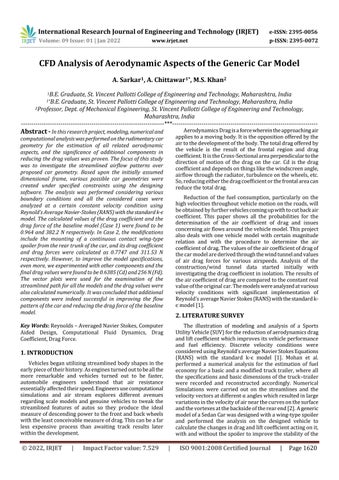
Fig. 1 2D draft of the Generic car geometry
3.1 Case 1: Inthefirstcase,thecargeometryisquitesimplewithall sharply inclined faces throughout its surface. This surface modelwaslatergivenathicknessof0.0025moneachface and converted to a solid part model. Based on the observations obtained on the above model, the modified versions of the existing geometry would be drafted and importedforfurtheranalysis. The chosen geometry is so simple that it is versatile enoughtobeworkeduponandhundredsofmodificationsare possible in its geometry; added to this, various additional components can be mounted on the cars. So, taking advantage of the same, it was decided that two of the modification ideas should be adopted in the existing geometryasexplainedinalaterstudy.

A2Doutlineofthissimplegeometrywasdraftedusing standarddimensionsandextrudedtoasignificantthickness usingthedesigningsoftware. Thisformofthemodelwasthenfittobeimportedinthe analysisprogrammingforrequiredtaskcomputations.
Fig.3 modified car geometry with Rooftop & Ducktail spoiler
4. COMPUTATIONAL ANALYSIS
In the second case, the original car is modified by mountingacontinuouscontactwing typespoilerattherear endofthecar. Wing typeSpoilerscreatevitaldownforceandtherefore give dependability decreasing lift. Particularly in the rear, there is stream partition because of which vortices are createdandtheycauseapressuredropintheaftregion.The spoilerusedforthiscaseisabitunconventionalinnatureas it is not open to airflow beneath the upper surface as we usuallysee.Thisstepwastakentojustifytherigidityofthe spoilerathigherspeeds.
Thedimensionsofthecararegiveninthefollowing: Length:0.36133m Width: 0.185m Height:0.152m Frontal Area of the car:0.0282m2 Density of the Medium:1.225kg/m3
ρisthedensityofthemediumcreatedinwhichtheobjectis subjectedtobeinmotion.Inourstudy,toknowthedensity
International Research Journal of Engineering and Technology (IRJET) e ISSN: 2395 0056 Volume: 09 Issue: 01 | Jan 2022 www.irjet.net p ISSN: 2395 0072
3.3 Case 3: In the second case, the original car was modified by mountingacontinuouscontactwing typespoilerattherear endofthecar.Weobservedsomechangesintheflowpattern overthesurfaceofthecar.Itwasalsoobservedthatthedrag coefficientandtheforceofdragwerealsoimprovedafterthe modification.Inall,thecar’saerodynamicstabilityimproved. Buttherewerestillsomelimitationslinkedtothemodified modelusedinthesecondcase.
Agenericmodelofacarwasconsideredwithandwithout a spoiler and it was used for determining its optimum aerodynamic structure. The analysis was performed for discretemodelsatsamevelocitiesandthedragcoefficient and drag force was determined. The main variables in the analysiswerethefrontalareaofthecar,thedragcoefficient and our prime objective was to reduce the drag force by draftingamodelhavingaspoiler.Toobtainthestreamlineair flowstructurearoundthecarbodywithandwithouttherear spoiler, this study was carried out on a numerical model using the fundamentals of Computational Fluid Dynamics (CFD).Boundary conditions were considered as an essential component of a mathematical model. They directed the motion of the streamlined air flow which led to a unique solution.Theformulausedforthecalculationofdragforce valueisshownbelow: ...(1) Intheaboveequation,densityofthemediumandvelocity ofairflowwouldbeconsideredasconstantentitieswhereas thefrontalareaandthecoefficientofdragvaluewouldbea variableentitywhiledeterminingthedragforceforallthe cases.Therearesomecertainassumptionsthataretobemade and certain values that are need to be calculated from the simulationsoftwareinordertocomputethedragforce.
© 2022, IRJET | Impact Factor value: 7.529 | ISO 9001:2008 Certified Journal | Page1622
3.2 Case 2:
Fig. 2 modeled car geometry having wing type spoiler Thedimensionsofthecararegiveninthefollowing: Length:0.345m Width: 0.185m Height:0.153m Frontal Area of the car :0.0283m2 Density of the Medium:1.225kg/m3
So,consideringthenotedlimitations,itwasdecidedthat thebaselinemodelshouldbeimprovedbythemountingroof andducktailspoilersthistime. This may reduce drag in specific cases and generally increasehigh speedstabilityduetothereducedrearlift.This model was imported for analysis and underwent aerodynamicanalysisandtherequiredoutputdealingwith theaerodynamicaspectsofthecarwasdrawnusingsuitable boundaryconditions.


V,thevelocityoftheairflowinthemediumagainstthecar isassumedtobe100km/hri.e.,27.77m/s.
Cd,isthecoefficientofdragofthecaranditisavariablefor allthecases.
Now,whenwesubstitutethevaluesinourmainequation (1),forceofdragvaluewasfoundouttobe, Fdrag= ×(1.225)×(27.7)2×(0.964)×(0.0279)=12.74N Asmentionedearlier,inordertosimplifythecalculations, theactualdimensionswerereducedtothescaleof1:30. ActualForceofDrag=12.74×30=382.2N 5.2 Case 2: Thedragcoefficientwasfoundtobe0.774.Forthisvalue ofCd,theforceofdragwascalculated.
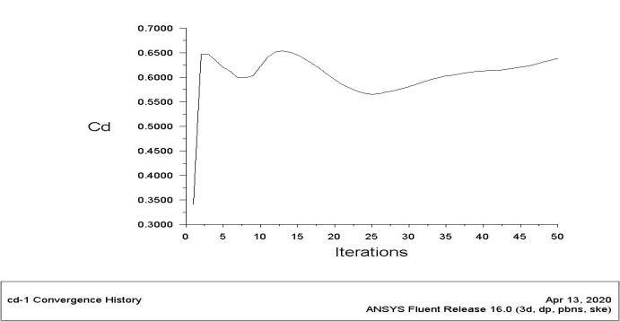
Thecomputationalandnumericalanalysisresultsforthe threecasesmentionedaboveareasfollows: 5.1 Case 1: The(Cd)valueiscalculatedusingtheanalyzingsoftware in which the drag coefficient value is determined by performing 50iterations. The graph between theCd value andtheno.ofiterationsperformedisshownbelow.Inthey axisweareconsideringtheCdvalueandinthex axisweare consideringtheno.ofiterationsperformed.Therefore,Inthis case,thedragcoefficientisfoundtobe0.964.Forthisvalue ofCd,theforceofdragiscalculated.
Fig. 7 Cd vs. no. of iterations performed for Case 2
of air, weneed the temperature of the medium, which is assumed to be at 288.16 K. Referring the Engineering Toolboxtable,1.225kg/m3isagoodapproximationforthe densityofairatthistemperature.
Fig. 4 Cd vs. no. of iterations performed for Case 1 Thedragforcevaluevarieswiththedragcoefficientand thefrontalareaofthecar.Asthesevalueschangewiththe boundaryconditions,theforceofdragalsochanges.Whereas inthiscase,thedragforcecalculatedintheanalysisofthe genericmodelofthecarisgivenbelow: Fig. 5 Net drag force acting on the body for Case 1
© 2022, IRJET | Impact Factor value: 7.529 | ISO 9001:2008 Certified Journal | Page1623
5. RESULTS
A,isconsideredasthefrontalareaofthecar.
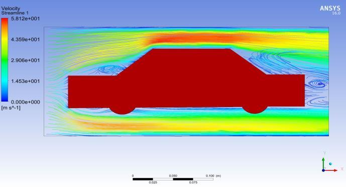
Thedragforcecalculatedintheanalysisofthiscarmodel havingwingtypespoileratitsrearendisgivenbelow: Fig. 8 Net drag force acting on the body for Case 2 Thedragforceobtainedbytheanalysisisequalto10.38N fordragcoefficientof0.774at100km/hrairvelocity.
It was nearly impossible to calculate the force of drag numericallyateveryinstantofthevaryingvelocityofthecar. So,forourstudy,wecalculatedthedragforceofthecarata certainfixedvelocitywiththefollowingobservations
International Research Journal of Engineering and Technology (IRJET) e ISSN: 2395 0056 Volume: 09 Issue: 01 | Jan 2022 www.irjet.net p ISSN: 2395 0072
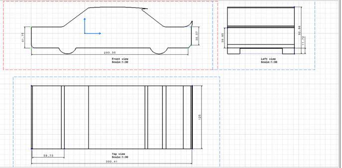
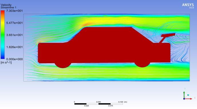
Inthiscase,theforceofdragcalculatedbythesoftware analysisisequalto12.74Nforadragcoefficientof0.964at 100km/hr(27.77m/s)velocityoftheairflow.Theairflow motionsareshowninthefollowingsubsections. Fig. 6 Streamline airflow of the isosurface plane for Case 1


International Research Journal of Engineering and Technology (IRJET) e ISSN: 2395 0056 Volume: 09 Issue: 01 | Jan 2022 www.irjet.net p ISSN: 2395 0072
© 2022, IRJET | Impact Factor value: 7.529 | ISO 9001:2008 Certified Journal | Page1624
Theforceofdragobtainedbythecomputationalanalysis wasequalto8.53Nfordragcoefficientof0.638at100km/hr (27.77m/s)airvelocity.Theairflowmotionsareshownin thefollowingsubsections.
Fig. 9 Streamline airflow of the isosurface plane for Case 2 As we have calculated the value of drag force for the baselinemodel,weareattemptingtoreduceitbyaddinga rearspoilertothecarandchangingtheflowpatternsofthe airnodes.Whileanalyzingtheflowpatternofthemodified car, it was observed that the flow patterns changed significantly and the drag coefficient value decreased providedothervaluesoftheequationremainedremarkably unchanged.Substituting all the values in the equation (1), the new dragforcewasfoundtobe, Fdrag= ×(1.225)×(27.7)2×(0.774)×(0.0283)=10.38N Toconvertthevaluesinaccordancewiththerealdimensions, ActualForceofDrag=10.38×30=311.53N Itwasobservedthatthespoilerweemployedimproved theaerodynamicaspectsofthevehiclebyreducingdragforce by2.5N.However,theoverallstructureofthisspoilerstill had some limitations and there was a visible scope of improvingtheresultsevenmoreifaratherbettermodelwas takenintoconsideration 5.3 Case 3: Thedragcoefficientisfoundtobe0.63853696,forwhich thedragforcewascalculated,forthecarhavingwingtype spoileratitsrearendisgivenbelow: Fig. 10 Cd vs. no. of iterations performed for Case 3
Fig. 12 Streamline airflow of the isosurface plane for Case 3
Wecalculatedthedragforceforthebaselinemodelwitha wingtypespoilermountedonthereartrunkofthecar,the results were satisfactory, but our main aim still lies with reducingthedragforceofthesamecarevenmorebygetting rid of the limitations possessed by the wing that we employed.So,thewingtypespoilerwasnowreplacedbythe roof spoiler added with a ducktail spoiler mounted on the reartrunkofthecartoacquirethebelowobservations.While analyzing the flow pattern of the modified car, it was observedthattheflowpatternschangedremarkablyandthe dragcoefficientvaluedecreasedprovidedwithuseoftherear wing. But when roof and ducktail spoilers were used as a replacement for the rear wing, following results were obtained.Substitutingallthevaluesintheequation(1),thedesired dragforcewasfoundtobe, Fdrag= ×(1.225)×(27.7)2×(0.638)×(0.0282)=8.53N
Toconvertthevaluesinaccordancewiththerealdimensions, ActualForceofDrag=8.53×30=256.00N
6. CONCLUSION Onperformingtheanalysiswiththegenericmodelofthe automobile body using three different cases at a given constantspeedof 27.77m/s,thedragcoefficientsactingonit weredeterminedbyperforming50iterationsforeachcase. Forthefirstcase,weconsideredthegenericmodelofthecar geometryinwhich,thedragcoefficientanddragforcewas foundtobe0.964and382.2Nrespectively.Forthesecond case, the car geometry was further improved with the
Fig. 11 Net drag force acting on the body for Case 2


[4] A. Parab, A. Sakarwala, B. Paste, V. Patil and A. Mangrulkar,“AerodynamicAnalysisofaCarModelusing Fluent Ansys 14.5,” International Journal of Recent TechnologiesinMechanicalandElectricalEngineering (IJRMEE),vol.1,2014,issue4,pp.007 013.
1 Genericcar 100 0.0279 0.964 382.2 2 Car with wing type spoiler 100 0.0283 0.774 311.53 3 Car with spoilerrooftop and ducktail 100 0.0282 0.638 256.00
International Research Journal of Engineering and Technology (IRJET) e ISSN: 2395 0056 Volume: 09 Issue: 01 | Jan 2022 www.irjet.net p ISSN: 2395 0072
[6] R. Bansal and R. B. Sharma, “Drag Reduction of Passenger Car Using Add On Devices,” Journal of Aerodynamics, vol. 2014, no. 678518, pp. 1 13, doi: 10.1155/2014/678518.
additionofanextracomponentsi.e.,awingspoilermounted onthereartrunkofthecar.Forthiscase,dragforceanddrag coefficient calculated was equal to 311.53 N and 0.774 respectively.Itwasevident
Thefollowingtableshowsalltheanalysisresultsobtainedin thisstudy: Table -1: Analysis of Drag Force values Drag coefficient values for all the 3 Cases
Cd Fd
REFERENCES
[5] S. P. Singh and A. Singh, “Design and Simulate an AerodynamicCarBodyforTheMarutiSuzuki800With LessCoefficientofDrag,”InternationalResearchJournal of Engineering and Technology (IRJET), vol. 03, 2016, issue06,pp.299 303.
[2] J. K. M. Mohan and B. Venkateshwarlu, “Numerical investigationontheaerodynamicsandfuelconsumption of a truck trailer,” International Journal of Applied Engineering Research(IJAER), vol. 9, 2014, no. 24, pp. 28957 28969
[9] S. Ruia and A. Dixit, “CFD Study of Aerodynamic performance of a popular Vehicle’s outer body Shape and Analysis of the effect of Aerodynamic Aids,” International Journal of Mechanical Engineering and Technology(IJMET),vol.6,2015,issue10,pp.171 193.
[8] A. B. Mohamed, M. S. Khatab and I. M. Ibrahim, “Computational Investigation of Spoiler Effect on the Aerodynamic Performance of Passenger Cars,” International Undergraduate Research Conference (IUGRC),2018.
Case Car type (m/s)v A (m2
[3] D. Patel, J. Jangid, Y. Devani, S. Goswami and M. Vachhani, “CFD Analysis on Aerodynamics of an Automobile Body,” International Journal of Scientific Research in Science, Engineering and Technology (IJSRSET),vol.4,2018,issue4,pp.778 783
[7] M.MohebbiandM.A.R.Baboli,“NumericalAnalysisof AerodynamicPerformanceofRegionalPassengerTrain underCrosswindConditions,”InternationalJournalof VehiclesStructures&Systems(IJVSS),vol.5,2013,no.2, pp.68 74,doi:10.4273/ijvss.5.2.05.
[12] M.N.Sudin,M.A.Abdullah,S.A.Shamsuddin,F.R.Ramli, M. M. Tahir,, “Review of Research on Vehicles Aerodynamic Drag Reduction Methods”, International Journal of Mechanical & Mechatronics Engineering (IJMME),Vol.14,2014,No.2,pp.35 47. ) (N)
From the study, it was concluded that the additional componentsmountedonthebasemodelofthecarimproved theaerodynamicstabilityofthecaratauniformspeed.They weresuccessfulinimprovingtheflowpatternofthecarand reducingthedragforceofthebaselinemodel.
© 2022, IRJET | Impact Factor value: 7.529 | ISO 9001:2008 Certified Journal | Page1625
[10] A.RainaandA.Khajuria,“AssessmentofFlowControl using Passive Devices around Bluff Bodies,” International Journal of Research in Applied Sciences andBiotechnology(IJRASB),vol.6,2018,issue1,pp.1 5. [11] V. Yakkundi and S. Mantha, “Effect of Spoilers of Aerodynamicspropertiesofacar,”InternationalJournal of Science Research and Review (IJSRR), vol. 7, 2018, issue3,pp.271 280.
that the results surpassed after the modificationsimplementedonthebaselinegeometrymodel. But, to improve the aerodynamic stability even more, the wing type modification was replaced by roof and ducktail spoilersandtheresultsobtainedwere256.00Nofdragforce andthedragcoefficientwasequalto0.638.
[1] G. S. Samy, S. T. Kumaran, M. Uthayakumar, M. SivasubramanianandK.B.Sankar,“Numericalanalysis of drag and lift coefficient of a Sport Utility Vehicle (SUV),”InternationalConferenceonRecentAdvancesin FluidandThermalSciences(ICRAFTS),vol.10,2019,no. 1088,pp.1 8,doi:10.1088/1742 6596/1276/1/012013