2. STATIC SYNCHRONOUS COMPENSATOR (STATCOM)
AtpresentStaticcompensators(STATCOM)are playingmajorroleinthemaintainingthevoltagestabilityof thetransmissionlines.Toreducetheripplecontentinthe output waveform of the STATCOM multilevel inverter topologiesareused.Themajorrequirementofthereactive powerdemandforinductivetypeofloadistomitigatedby STATCOM to reduce the burden along with the reactive power,realpowerisalsorequiredtobeprovidedtoreduce theeffectofvoltagedropbeingcausedbytheresistanceof the Transmission lines. STATCOM is a power electronics withmultilevelratingtransmissionpower.multilevelSTATCOMcompensationbebasedshuntconnectedcompensatingdevicewhichprovestoveryusefultoprovidereactiveandrealpowerinthedistributionline.Inthispaper,usingwiththeintegrationofDiodeclampedthreelevelinverterisusedtosupplybothrealandreactiveTheresultsareverifiedMATLAB/SIMULINKalineof25KVsisusedandwithSTATCOMof+/1MVAisused.Theresultsshowsthattheinvertermaintainsvoltagestabilityoftheloadlessharmoniccontentinvoltagewaveforms
1Professor, Department of Electrical and Electronics Engineering, UCEK, JNTU Kakinada, India
INTRODUCTION
The basic structure of the STATCOM is converter that producesasynchronoussinusoidalvoltage.Voltagesource Inverter(VSI)aremostlyusedintheapplicationof the
2M.Tech, Department of Electrical and Electronics Engineering, UCEK, JNTU Kakinada, India ***
continuouspowerflowcontrolandpowersystemstability improvement [1]. The interaction between the ACsystem voltage and the inverter composed voltage provides the control of the STATCOM var output. When these two simultaneousshowsovertwoBridge(CHB).clippedsourcegatheringsForwhichmethodsMultilevelstaggeredTheoptionanmediumhascanDCforwhileuppowerfulrequirehighNumerousoutputapplicationsTheoneandvariousactivevoltagesaresynchronizedandhavethesameamplitude,theandreactivepoweroutputsarezero.Thereareconverterconfigurationsavailableforbothsinglethreephaseapplications:Thesinglephasehalfbridgeisalegconvertorconsistingoftwoswitchingelements.HbridgeVSCismostpopularforsinglephasebecausewiththesameDCinputvoltagetheofthefullbridgeistwicethatofthehalfbridgemechanicalapplicationshavestartedtorequirepowerasoflateSomemachinesintheventuresanywaymediumorhighpowerfortheiractivity.Utilizingahotspotforeverysinglemechanicalloadmayendbeingvaluabletoafewenginesrequiringhighpoweritmightharmalternateburdens.Invertersareutilizedsomeapplications,asincircumstanceswherelowvoltagesourcesmustbechangedoverwiththegoalthatgadgetskeeprunningoffofACcontrol.Thestaggeredinverterbeenpresentedsince1975asoptioninhighpowerandvoltagesituationsthestaggeredinverterresemblesinverteranditisutilizedformodernapplicationsasaninhighpowerandmediumvoltagecircumstances.staggeredinvertercomprisesofafewswitches.Intheinverterthegameplanswitchesedgesarecriticalinvertergoesuptohighexchangingvoltagebyforaprogressionofvoltagesteps,everyoneofisrelyupontheratingofintensitygadgetsseparately.staggeredinverter,afewtopologiesareorderedintworelyinguponthequantityofautonomousdcThemostwellknownworkingtopologiesarediode(NPC),flyingcapacitor(FC)andCascadedHANPCinverterisfundamentallymadeoutofordinarytwolevelvoltagesourceinverterstackedaretheotherwithsomeminoradjustments.Thispapertheregulationofvoltageacrosstheloadwithbothcontrolofrealandreactivepowercontrol[2].
Real and Reactive Power Compensation by using Diode Clamped Multilevel Inverter based STATCOM Dr. T. Murali Mohan1, G. Manohar Brahmam2
International Research Journal of Engineering and Technology (IRJET) e ISSN: 2395 0056 p ISSN: 2395 0072Volume: 09 Issue: 01 | Jan 2022 www.irjet.net © 2021, IRJET | Impact Factor value: 7.529 | ISO 9001:2008 Certified Journal | Page1599
Key Words: Power quality, voltage sag, Voltage swell, STATCOM, Multilevel inverter, Diode clamped multilevel inverter,Simulink 1. Theexponentialgrowthintheelectricalenergyusage daybyday,combinedwithdemandforlowcostenergy,has gradually led to the development of generation sites remotely located from the load centre. The usage of lineincreasereactivethesource.compensatorcompetitivethyristor(STATCOM),requirement.withstabiliseplaces.istransmissionlinestoconnectgeneratingsitestoloadcentresrequiredforthegenerationofbulkelectricityatremoteActiveregulationofreactivepowerisrequiredtothepowersystemandsustainthesupplyvoltagelongdistanceacpowertransmissionandloadpowerThestaticsynchronouscompensatorwhichusesvoltagesourceinvertersinsteadofcontrolledreactors,hasbeenapprovedasaalternativetothetraditionalstaticvar(SVC).STATCOMactsasasynchronousvoltageItcanprovidereactivepowercompensationwithoutdependenceontheacsystemvoltage.Bycontrollingthepower,aSTATCOMcanstabilizethepowersystem,themaximumactivepowerflowandregulatethevoltages.FasterresponsemakesSTATCOMsuitablefor
Abstract -

Themosteconomicalandpracticalconfiguration thatispresentlyutilizedandsuggested. High power utility applications are multiphase converters. Therealpowersuppliedbythedclinkcapacitoriszero,thusit suppliesonlytherequiredreactivepowerdependuponthe control phase and magnitude of the gating pulses of the statcomsincereactivepoweratzerofrequencyi.e.Capacitor waveformsystem.thecurrentisthetotheimportantcreatedNonetheless,ofphasespowerinvoltageisbydefinitionzero,thedccapacitorhasnoinfluencetheresponsivepowerage.Inotherwords,thereactivegenerationisduetotheinterconnectionoftheACbytheconverterinsuchawaythatthereactivepowertheACsystemcanflowfreelyfromtheACphases.despitethefactthatreactivepowerisinsidebytheactivityofsolidstateswitches,itisasyettohavesomesomewhatlittledccapacitoracrossterminalsoftheconverter[3].Therequirementforthedccapacitorisprincipallyneededfulfilthebalancebetweentheinputandoutputpowersofconverter.Theresultvoltagewaveformoftheconverternotanidealsinewave,smoothwavenearlytoosinusoidalisachievedthroughtheuseofmultileveltopologiesinstatcomthroughthetiereactanceofthetransmissionAsaresultofreducedripplecontentintheoutputthenetthreephasepowerhaslessripples.
2. 1. Basic operation of STATCOM
(Vc 2 -VcVs*cosα)/X (3)
voltage X
Certified Journal | Page1600
| ISO
From Fig. 1 shows that STATCOM consists of a power powertransmissionsystemvoltagethetheinaloneandtheythepowerthethroughsourcesprinciplethesynchronizedphasereactivewhichwhichinverter)theelectronicdevicewhichconvertstheD.CtotheA.Cknownasinvertergenerallythreephaseinverter(generallyaPWMusingSCRs,MOSFETsorIGBTs,adccapacitorprovidesthedcvoltagefortheinverter,atransformeractsasaleakageinductancewhichplaysmajorroleinpowerflow.Fromthedcsidecapacitor,athreevoltageisgeneratedbytheinverter.Thisiswiththeacsupply.TheleakageinductorlinksinverterD.Cvoltagetotheacsupplyside.ThebasicofoperationofSTATCOMisthat,fortwoacwhichhavethesamefrequencyandareconnectedaseriesinductance,theactivepowerflowsfromleadingsourcetothelaggingsourceandthereactiveflowsfromthehighervoltagemagnitudesourcetolowervoltage[2].InconventionalconverterswhichistwolevelinverterdonothavethecapabilityofvoltagemagnitudecontrolonlythephaseangleoftheACoutputwaveformcanbecontrolledbythegatingpulsesofthestatcom.ButmultilevelinverterthereisacapabilityofcontrollingbothmagnitudeoftheACoutputwaveformandphaseangleofoutputACvoltagewaveformVoltage(Vs)istheACgeneratedfromthestatcomandthetransmissionvoltage(Vt).IfVslagsVt,realpowerflowsfromsystemtodcside.SimilarlyifVsleadsVt,realflowsfromthedcsidetothetransmissionsystem.
voltage Vs is theAC
/x
© 2021, IRJET | Impact
International Research Journal of Engineering and Technology (IRJET) e ISSN: 2395 0056 p ISSN: 2395 0072Volume: 09 Issue: 01 | Jan 2022 www.irjet.net statcoms.
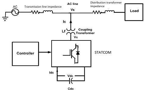
Fig 1: BlockdiagramofSTATCOM 2.2. Power flow equations of STATCOM Diode clamped MLI based STATCOM is connected to the linethroughcouplingtransformer.TheVSCandacapacitor connectedatDCside.HereathreeleveldiodeclampedMLIis equationusedasstatcomasshowninfig2.Thecurrentflowingfromthestatcomisderivedfromthebelowas,Ic=(VcVs) (1) followsActivepowerfromthestatcomisgivenbytheequationasP=(Vc*Vs/x) (2) Reactivepowerfromthestatcomisgivenbytheequation asfollowsQ= Where Vc istheinverteroutputAC bus istheleakagereactanceofcouplingtransformer α isthephaseanglebetween Vs and Vc Ic is powersystem.themagnitudeofSTATCOMcurrentinjectingintotheFromtheaboveequations(1),(2),(3)itrepresentstheflowequationsfromthestatcom. Factor value: 7.529 9001:2008
*sinα
Thereforetherealpowerexchangeisafunctionofphase displacement(Δα).
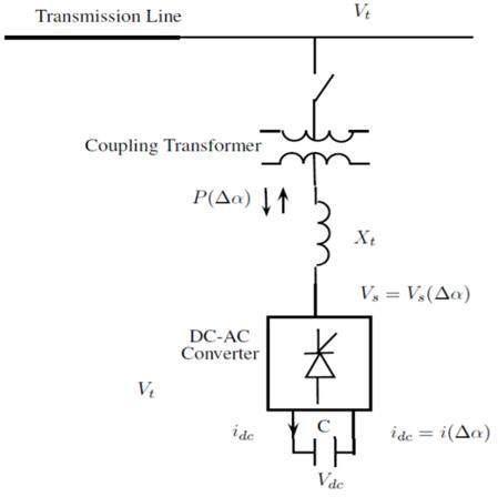
Table 1: SwitchingstatesofDC MLI SwitchState State PoleVoltage
© 2021, IRJET | Impact Factor value: 7.529 | ISO 9001:2008 Certified Journal
International Research Journal of Engineering and Technology (IRJET) e ISSN: 2395 0056 p ISSN: 2395 0072Volume: 09 Issue: 01 | Jan 2022 www.irjet.net
3. Multilevel inverter topologies
T3=ON,T4T1=OFF,T2=ON=OFF S=0 Vao=0
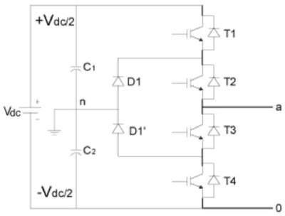
Fig 3: SinglelegofthreelevelDiodeclampedmultilevelinverter
| Page1601
T1=OFF,T2=OFF, T3=ON,T4=ON S= VE Vao= Vdc/2
At any time a set of two switches is on for a three level inverter.Table.1showstheswitchingstatesinonepartofthe three leveldiodeclampedmultilevel inverter.Inathreelevel diode clamped inverter, there are three altered achievable switching states which are allowed to obtain the stepped waveformnearertosinewaveonoutputvoltagerelatingtoDC linkcapacitorvoltagevalue.
There are mainly three different multilevel converter structuresarewidelyusedinindustrialapplications. Theyare i. Diodeclampedinverter ii. Flyingcapacitormultilevelinverter iii. Cascaded H bridge converter with separate dc sources. The circuit design is more complex, as the presenceof large number of switches in the circuit, the control of the inverter.andvoltagevoltageasinverter,neutralchangeobtainedofswitchesincircuitiscomplicatedtoobtaintheoutputvoltagedifferentlevelswithsmootheroutputwaveforms.Thewaveformhasdecreasedharmonicdistortionsandinvoltagepersecondacrosseachswitchisreduced.Diodeclampedinverterwhichisalsocommonlycalledasfedinverterismostcommonlyusedmultileveltoachievestepsinoutputvoltagethediodeisusedclampingdevicewhichishelpfultoclampthedcbusbustogetdifferentlevels.Thus,diodeisusedtolimitthestress.InthistopologytherearetwopairsofswitchestwodiodeareconsistsinathreeleveldiodeclampedThevoltageacrosseachcapacitorandeachswitchis
Fig 2:
Vdc. The quality of the output voltage is improved by increasing the number of voltage levels and the voltage waveform becomes closer to sinusoidal waveform. The diodes used to provide access to mid point voltage and all switch pairs work in complimentary mode. The DC bus voltage is divided into three voltage levels with the help of twoseriesconnections ofDCcapacitors,C1andC2.Withthe assistance of the clamped diodes the voltage stress across each power electronic switch is inclined toward Vdc. It is assumed that the absolute dc link voltage is Vdc and mid point is synchronized at half of the dc interface voltage, the voltage across every capacitor is Vdc/2 (Vc1=Vc2=Vdc/2). In a diode clamped three level inverter, there are three unique possibleswitchingstates.Onlytwoswitchesisonforathree levelinverteratanyinstantoftime[6].
gridstatcomnegativversamagnitudeflowstatcomstatcomstatcomflowFromSchematicdiagramofSTATCOMwithpowersystemtheequation(2)itshowsthat,theactivepowerfromthestatcomispositivewhengridvoltageleadsthevoltageviceversatheactivepowerflowfromtheismadenegativebymakinggridvoltagelagsthevoltageie..,statcomsuppliesrealpowertothegrid.Fromtheequation(3)itshowsthat,thereactivepowerfromthestatcomismadepositivewhengridvoltageislargerthanthestatcomvoltagemagnitude,vicethereactivepowerflowfromthestatcomismadeebymakinggridvoltagemagnitudelessthanthevoltageie..,statcomsuppliesreactivepowertothe[3].
T3=OFF,T4=OFFT1=ON,T2=ON S=+VE Vao=Vdc/2
V (n)isgivenas: V (n)= V ∗(n) V (n 1) (4) Theoutputofthe
International Research Journal of Engineering and Technology (IRJET) e ISSN: 2395 0056 p ISSN: 2395 0072Volume: 09 Issue: 01 | Jan 2022 www.irjet.net
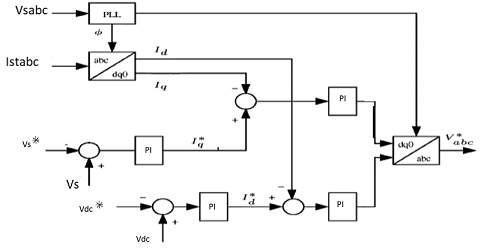
Figure 4 shows the internal view of Synchronous Reference Frame Theory (SRF) control strategy for STATCOM.InthiscontrolstrategytheSRF basedSTATCOM control technique is used to generate gate pulses for controlling ofSTATCOM.Herefromthecontrol strategy is designedwithabcframetod qframeconversionblock,PLL block,HPF,PIcontroller,DQtoABCconversionblock.The abc frametod qframeconversionblockconverts 3Øload current parameters (Iabc) todq0 parameters frame byusing parks transformation. The phase locked loop generates Sinwt and coswt signals for transformation block. Initially, the current components from block in α β co ordinates are generated. Iabc of statcom current phases can then be transformedintoα βcoordinates.HPFishighpassfilteris used to block low frequency components coming from conversion block then given to inverse transformation block and then the output of inverse transformation block is STATCOM reference current which will generate gate pulses forswitches[4]. 3.3. Design of PI controller Inthispaper,simulationisdonebyusingproportional integral(PI)controller.TheDCreferencevoltageandDClink voltage are compared and the error is generated and controlledbyPIcontrollerwhichgenerates thedirectaxis componentofthereferencegridcurrent.Thegridreactive powpowerandreferencereactivepower(referencegridreactiveer, Qref = zero) are compared and controlled by PI controller which generates quadrature axis component of referencegridcurrentasshowninFigure4.ThecontrollerusedisdiscretePIcontroller that takes thevaluereferencevalueandactualvalueandgeneratesthemaximumofreferencecurrent,whichdependsontheerrorsinreferencevalueandactualvalue.Thevoltageerror PIcontroller
Fig -4: D Qcontrolstrategy
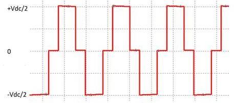
Fig -3: Outputwaveformvoltageforasinglephase 3.2. PI controller The block diagram of a proposed control technique is showninfig.4.Therefore,thePLLprovidestheangleφtothe abcto dq0 (and dq0 to abc) transformation. There are also fourproportional integral(PI)regulators.
atthenthinstantis: I (n)= I (n 1)+ Kp * [V (n) V (n 1)]+ Ki V (n) (5) referenceTheequationsofdirectandquadratureaxiscomponentofgridcurrentare,I d= ( Kp+Ki/s) *( Vref * V) (6) Id= ( Kp+Ki/s) *( Vdc * Vdc) (7) Where Kp proportionalgain Ki integralgain Vdc * referenceDClinkvoltage Vdc measuredDClink voltage Vref * reference loadvoltage V measured loadvoltage © 2021, IRJET | Impact Factor value: 7.529 | ISO 9001:2008 Certified Journal | Page1602
3.1. Switching configuration of Diode Multilevel inverter topologies belowcircuitconfigurationproducingswitcheslessT2,belowsignaloff,thansignalproducingswitchesthanreferencefrequencyDuringthetriangularcarrierwavecomparisontwohightriangularwavesareusedtocomparewiththesinewave,ifthereferencephasesignalisgreaterthetwotriangularcarrierwavesthentheT1,T2areturnedonandT3,T4switchesareturnedoffontheoutputvoltageasVdc/2.IfthereferencephaseisnotgreaterthanabovetriangularwaveandgreaterbelowtriangularwavethenT1,T4switchesareturnedT2,T3switchesareturnedon.IfthereferencephaseisnotlessthanabovetriangularwaveandnotlessthantriangularwavethenT1,T4switchesareturnedoff,T3switchesareturnedon.IfthereferencephasesignalisthanboththetriangularcarrierwavesthenT1,T2areturnedoffandT3,T4switchesareturnedonoutputvoltageasVdc/2[6].Theoutputvoltageobtainedbytheaboveswitchingisobtainedasshowninbelowfigure.Thediagramrepresentingaboveswitchingisshowninfigure.
4. 1 When under RL Load RLloadof100MVAconsistingof70MWofresistive increaseconditionsload.loadand52.5MVARofinductiveloadisconsideredtobeasaTheSTATCOMoperationatloadsidefordifferentsuchasdecreaseinvoltageie..,voltagesagandinthevoltageie..,voltageswellaretobetested.
4. 1. 1 Voltage Sag there will be variations in the voltage of the
International Research Journal of Engineering and Technology (IRJET) e ISSN: 2395 0056 p ISSN: 2395 0072Volume: 09 Issue: 01 | Jan 2022 www.irjet.net 4. MODELING THE STATCOM USING THE SIMULINK’S POWER SYSTEM BLOCKSET networkcontrolASTATCOMisapowerelectronicsystemwithacomplexsystem.ModellingtheSTATCOMincludingthepoweranditscontrollerinSimulinkenvironmentrequires
A
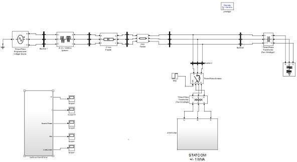
“electric blocks” from the Power System Block set and controlblocksfromSimulinklibrary.Weconsiderherea +1Mvar STATCOM connected to a 25 kV distribution network usedusedcapacitorinverterconsistingofthroughSTATCOMMVAconnected21representedSTATCOMFigure5showsaSimulinkdiagramwhichrepresentstheandthedistributionNetwork.ThefeedingnetworkisbyaTheveninequivalent(busBl)followedbyakmfeederwhichismodelledbyapiequivalentcircuittobusB2.A25kV/2500Vtransformeranda100loadareconnectedtobusB2bya2kmfeeder.Theoutputiscoupledinparallelwiththenetworkastepup2.5/25kVYYtransformer.TheprimarythistransformerisfedbyavoltagesourcePWMinverteroftwoIGBTbridges.Afilterbankisusedattheoutputtoabsorbharmonics.A6600microfaradsisusedasdcvoltagesourcefortheinverter.APWMpulsegeneratorwithacarrierfrequencyof2kHzistocontrolbothIGBTbridges.ThemodulationschemeisofLevelshiftsinusoidaltypePulsewidthmodulation andbothunderRLThesimulationisdoneundervariationtypesofloadsuchasLoad,RCLoad,andRLoad.ThebehaviorofthestatcomcorrectionoftheloadvoltageisobservedduringthecasessuchasVoltageSagwhichfrom1p.uto0.98p.uVoltageSwellwhichisfrom1p.uto1.02p.u.
.
. Table -2: Systemparametersandvalues System Parameters Values Sourcevoltage 25000volts Transmissionlinerating 25kv/100MVA Transmissionimpedanceline 0.1p.uresistance, 1p.ureactance DistributionTransformer 25kv/415volts R load 70e6MW RL Load 52.5e6MVAR RC Load 52.5e6MVAR 4. 1 SIMULATING THE STATCOM OPERATION MODELING THESTATCOMUSINGTHESIMULINK’S POWER SYSTEM BLOCKSET TheSimulinkdiagramshowninFig.5hasbeenusedto simulatethe operationof theD STATCOM under different source.simulatedbeseconds).Initiallydoneconditionstoillustrateitsperformance.Thesimulationwasusingadiscretesteptime(T=50microthestatcomisinopenstate.AstherewillvariationsinthevoltageofthetransmissionsystemitisintheSimulinkbyusingprogrammablevoltage Fig 5 SimulinkdiagramrepresentingSTATCOM
As
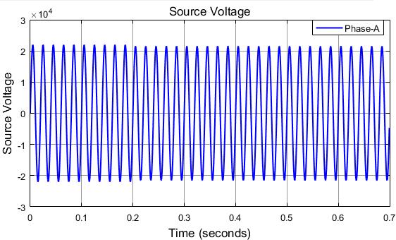
fromatSourcevoltagevoltagevoltageprogrammabletransmissionsystemitissimulatedintheSimulinkbyusingvoltagesource,whereitisprogrammedtoitfrom1p.uvoltageto0.98p.uvoltageresultsinthesagattimeof0.3seconds.ThedecreasedinthecanbeobservedfromthepowerwaveformsoftheThestatcomisconnectedtothetransmissionsystemthe0.5secondstoincreasethevoltageatloadto0.98p.uthe1p.ubytheproperactiontakenbystatcom.
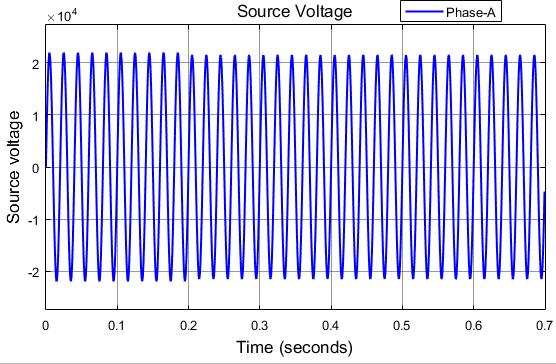
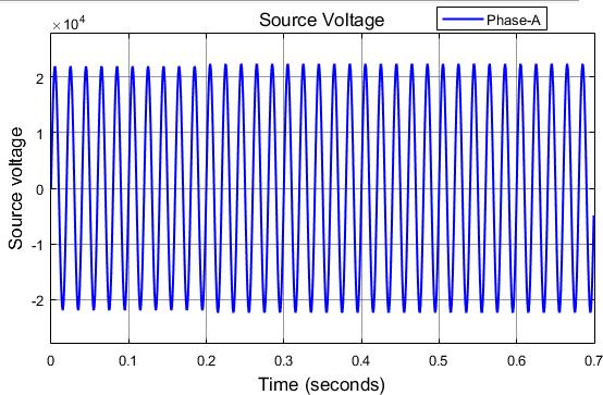
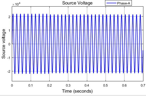
Fig 6.1.1 SourceVoltage © 2021, IRJET | Impact Factor value: 7.529 | ISO 9001:2008 Certified Journal | Page1603
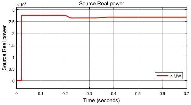
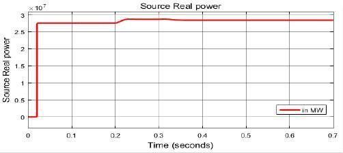
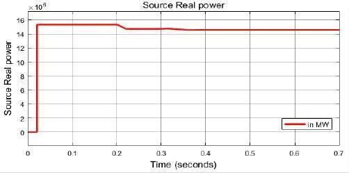
At time t=0 sec, the real power drawn from the sourceis9MWaftertheconnectionstatcomtherealpower drawnfromthesourceisreducedto8.2MW.
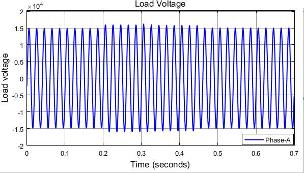
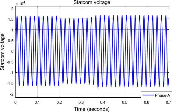
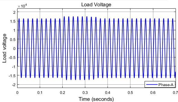
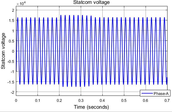
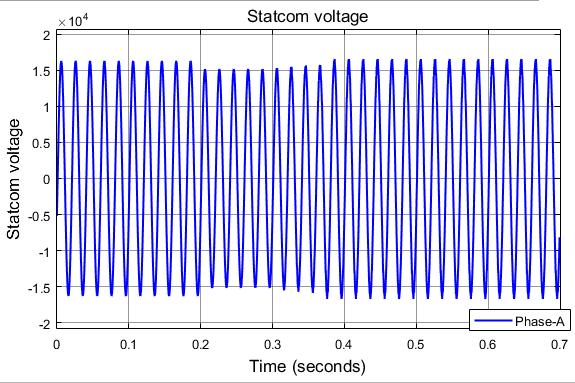
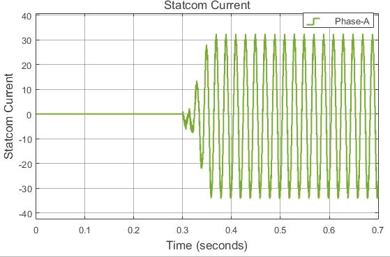
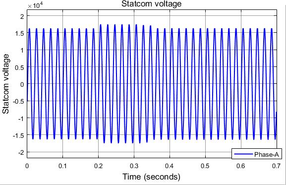
Attimet=0sec,thestatcomvoltageisatvalueof1p.u loadthe0.98Whentimereaches0.2sec,thereisdecreaseinthevoltagetop.uwiththereductionofthevoltage.Attimet=0.3sec,statcomismadetoconnectandthevoltageacrosstheismadetobringtothe1p.u.
SourceRealPower
Attimet=0sec,thevoltageofthesourceisat1p.u After 0.2sec,thevoltageisreducedfromits1p.uto0.98p.u.itcanbe observedfromtheabovewaveform.
Fig -6.2.1-StatcomVoltage
Certified Journal | Page1604
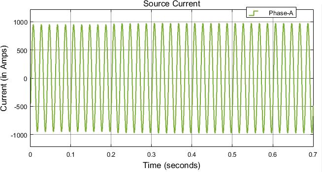
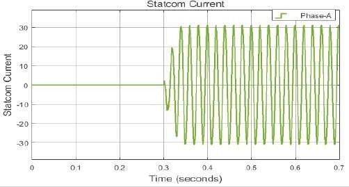
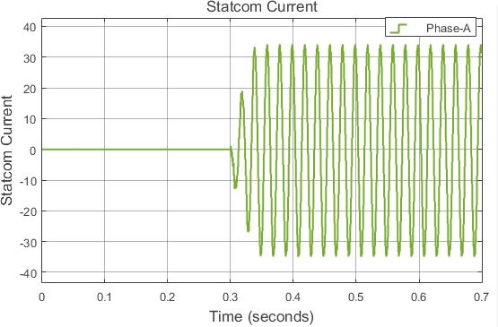
Attimet=0sec,thecurrent drawnfromsourceisat normalvalue,att=0.2secthereisdecreaseinvaluedueto decreaseinvoltage.After0.3sec,thestatcomconnectionto the system made the system to draw less current than it requires.
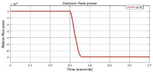
Attimet=0 sec, thepower supplied by statcomis made to zero, when there is reduction voltage at load at t=0.3secthestatcommakestheappropriatecontrolaction tosupplyrequiredamountofpowertoload.
Fig 6.1.3
©
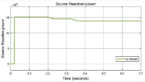
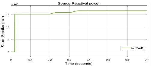
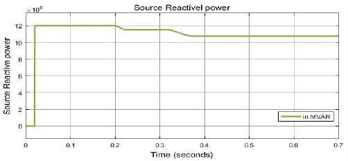
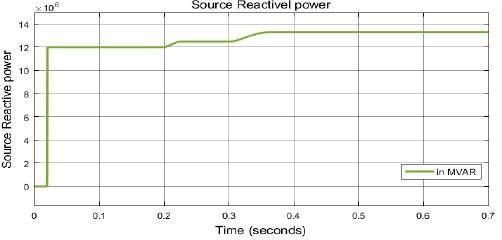
Attimet=0sec,thereactivepowerdrawnfromthesource is 15 MVAR, after connection of statcom at 0.3 sec the reactivepowerdemandbytheloadisreducedby1MVAR.
SourceReactivePower
International Research Journal of Engineering and Technology (IRJET) e ISSN: 2395 0056 p ISSN: 2395 0072Volume: 09 Issue: 01 | Jan 2022 www.irjet.net
Fig 6.1.4
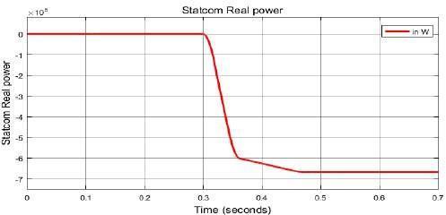
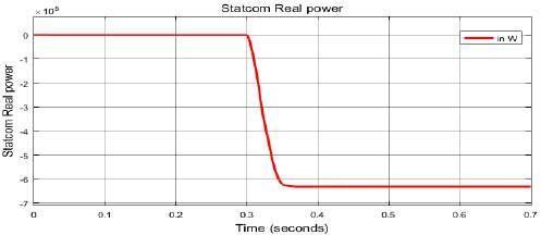
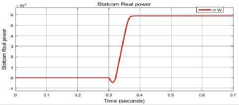
Fig 6.2.3 StatcomRealPower
Attimet=0sec,thestatcominclosedposition.Aftert=0.3sec, thestatcom is made toconnect to theloadto producethe required amount of real power demanded by the load to maintainitvaluenormalto1p.u. 2021, IRJET | Impact Factor value: 7.529 | ISO 9001:2008
Fig 6.2.2 StatcomCurrent
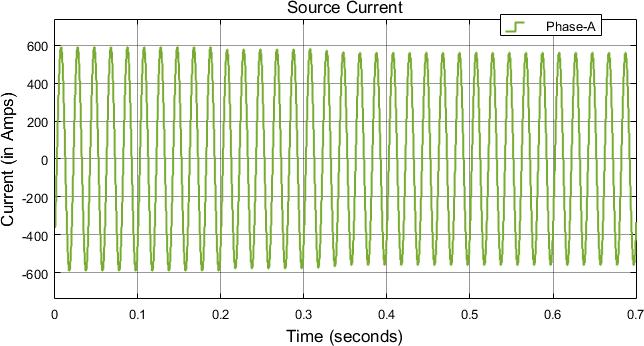
Fig 6.1.2 SourceCurrent
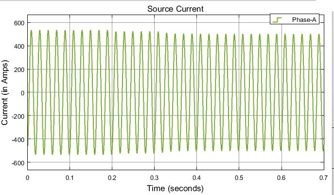
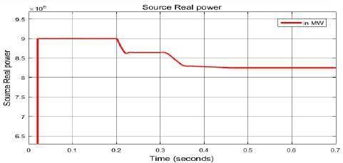
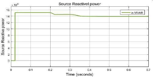
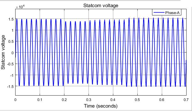
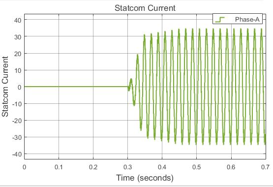
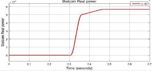
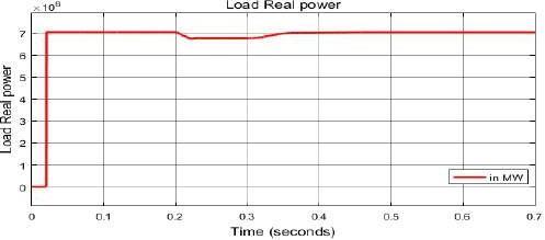
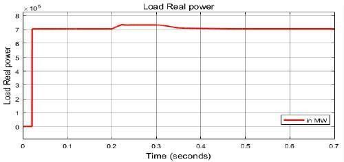
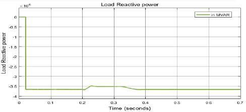
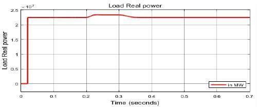
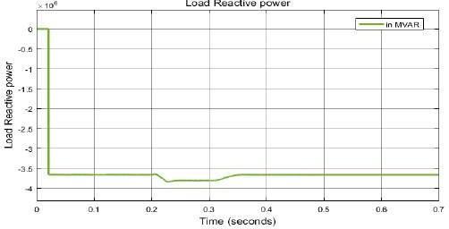
Fig 6.3.3 LoadRealPower
As there will be variations in the voltage of the fromtheSource.voltagevoltagevoltageprogrammabletransmissionsystemitissimulatedintheSimulinkbyusingvoltagesource,whereitisprogrammedtoitfrom1p.uvoltageto1.2p.uvoltageresultsintheswellattimeof0.3seconds.TheincreaseinthecanbeobservedfromthepowerwaveformsoftheThestatcomisconnectedtothetransmissionsystemat0.5secondstodecreasethevoltageatloadto1.2p.uthe1p.ubytheproperactiontakenbystatcom. 2021, IRJET | Impact Factor value: 7.529 | ISO 9001:2008
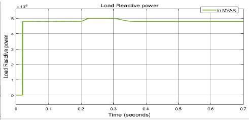
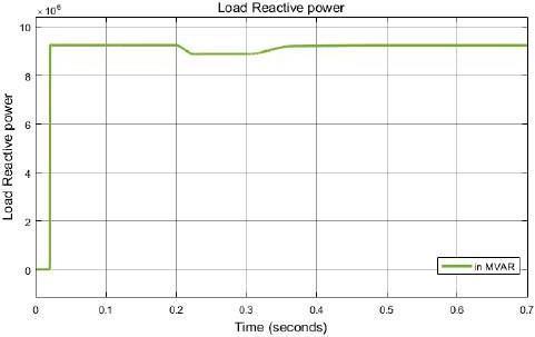
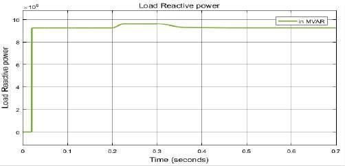
Fig -6.3.4-LoadReactivePower
©
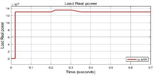
Itisobservedfromthewaveformthatatt=0sec,the load is drawing its required power. After 0.2 sec there is decreaseinpower duetodecreaseinvoltage, thestatcom power.connectedat0.3secmakestheloadtodrawthedesiredreal
Certified Journal | Page1605
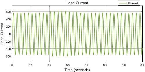
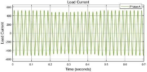
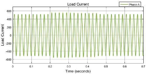
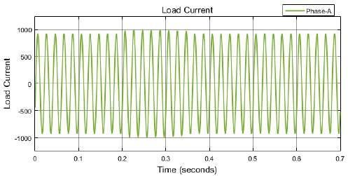
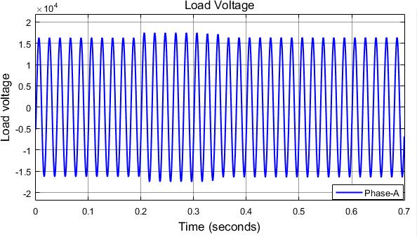
Attimet=0sec,asthevoltageacrosstheloadismade1p.u theloaddrawstherequiredamountofcurrent.Asthereis reductioninvoltageat0.2sec,thereisreductioninvalueof current.At0.3sec,thestatcomis madetoconnect toload makestheloadtodrawtherequiredamountofcurrent.
International Research Journal of Engineering and Technology (IRJET) e ISSN: 2395 0056 p ISSN: 2395 0072Volume: 09 Issue: 01 | Jan 2022 www.irjet.net
Itisobservedfromthewaveformthatatt=0sec,the load is drawing its required power. After 0.2 sec there is decreaseinpower duetodecreaseinvoltage, thestatcom connected at 0.3 sec makes the load to draw the desired Fromreactivepower.thewaveformsoftheFigure6itisobservedthatthe statcomisabletocompensateboththeactiveandreactive powerbyactingstatcomasinthecapacitivesupplyingboth activeandreactivepowerfromthesupply.
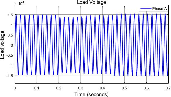
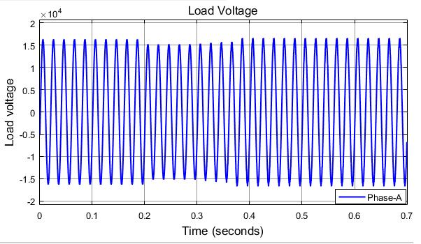
Fig -6.3.1-LoadVoltage
4. 1. 2 Voltage Swell
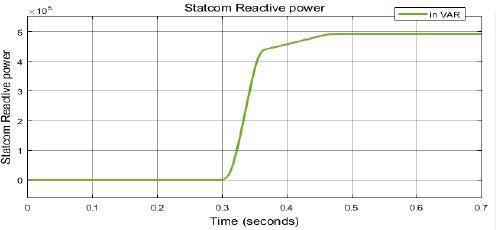
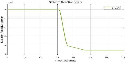
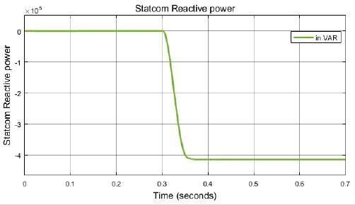
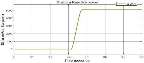
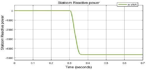
Fig 6.2.4 StatcomReactivePower
Initiallythevoltageacrosstheloadismaintainedat1p.u supply.whichThestatcomreductionvalue,after0.2secduetoreductioninsourcevoltagethereisinvoltagevaluefrom1p.uto0.98p.u.Att=0.3secisconnectedtobringbackthevoltageto0.3sec.statcomsuppliesthepowerdemandedbytheloadisreducedduetodecreaseinthevoltageofthe
Fig 6.3.2 LoadCurrent
Attimet=0sec,thestatcominclosedposition.Aftert=0.3 mairequiredsec,thestatcomismadetoconnecttotheloadtoproducetheamountofreactivepowerdemandedbytheloadtontainitvaluenormalto1p.u.
© 2021, IRJET | Impact Factor value: 7.529 | ISO 9001:2008 Certified Journal | Page1606
Fig 7.2.2 StatcomCurrent
At time t=0 sec, the current drawn from source is at normalvalue,att=0.2secthereisincreasesinvaluedueto increaseinvoltage.After0.3sec,thestatcomconnectionto the system made the system to draw more current thanit requirestoreducemoredropacrosslinestoreducevoltage acrosstheload.
Fig 7.1.1 SourceVoltage
Fig -7.1.2-SourceCurrent
Fig 7.1.3 SourceRealPower
Attimet=0sec,thevoltageofthesourceisat1p.u.After 0.2 sec,thevoltageisincreasedfromits1p.uto1.02p.u.it canbeobservedfromtheabovewaveform.
Fig -7.1.4-SourceReactivePower
International Research Journal of Engineering and Technology (IRJET) e ISSN: 2395 0056 p ISSN: 2395 0072Volume: 09 Issue: 01 | Jan 2022 www.irjet.net
power15Attimet=0sec,thereactivepowerdrawnfromthesourceisMVAR,afterconnectionofstatcomat0.3secthereactivedemandbytheloadisincreasedby2MVAR.
Fig -7.2.1-StatcomVoltage
madestatcomp.utimeAttimet=0sec,thestatcomvoltageisatvalueof1p.uWhenreaches0.2sec,thereisincreaseinthevoltageto1.02withtheincreaseinthevoltage.Attimet=0.3sec,theismadetoconnectandthevoltageacrosstheloadistobringtothe1p.u.
Attimet=0sec,therealpowerdrawnfromthesourceis9 theMWaftertheconnectionstatcom,therealpowerdrawnfromsourceisincreasedto10MW.
Attimet=0sec,thepowersuppliedbystatcomismadeto requiredthezero,whenthereisincreaseinthevoltageatloadatt=0.3secstatcommakestheappropriatecontrolactiontosupplyamountofpowertoload .
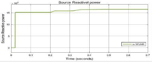
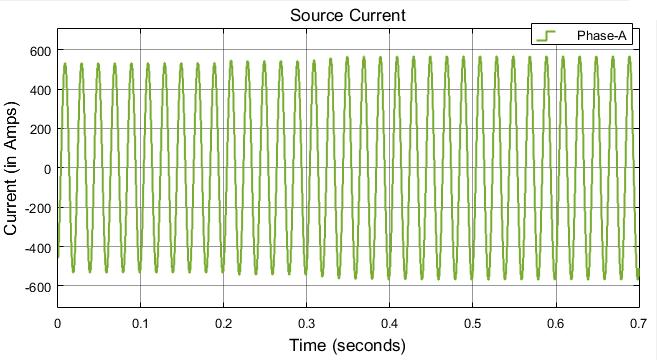
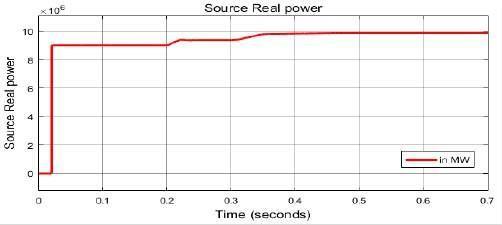
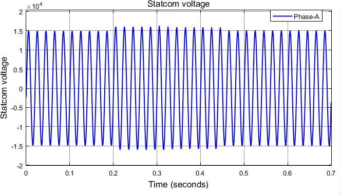
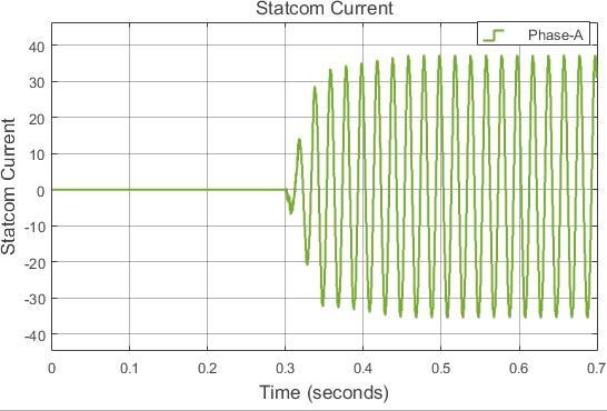
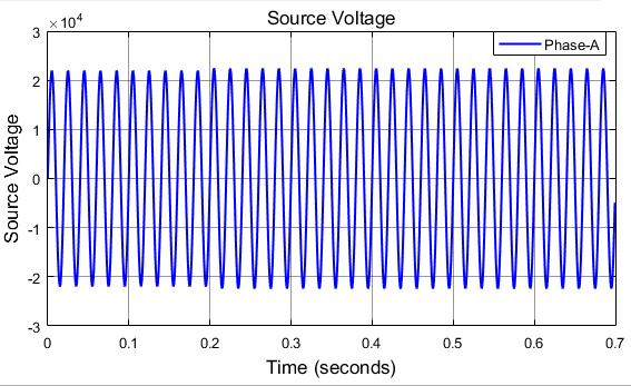
Fig 7.3.1 LoadVoltage
Page1607
Fig 7.2.3 StatcomRealPower
Fig 7.3.3 LoadRealPower
Itisobservedfromthewaveformthatatt=0sec,the load is drawing its required power. After 0.2 sec there is increaseinpowerduetoincrementinvoltage,thestatcom power.connectedat0.3secmakestheloadtodrawthedesiredreal
International Research Journal of Engineering and Technology (IRJET) e ISSN: 2395 0056 p ISSN: 2395 0072Volume: 09 Issue: 01 | Jan 2022 www.irjet.net
Fig -7.3.2-LoadCurrent
Itisobservedfromthewaveformthatatt=0sec,the load is drawing its required power. After 0.2 sec there is increment in power due to increase in voltage, the statcom connected at 0.3 sec makes the load to draw the desiredreactivepower. © 2021, IRJET | Impact Factor value: 7.529 | ISO 9001:2008 Certified |
Attimet=0sec,thestatcominclosedposition.Aftert=0.3sec, the statcom is made to connect to the load to absorb the requiredamountofrealpowernotrequiredbytheloadto maintainitvaluenormalto1p.u.
Attimet=0sec,thestatcominclosedposition.Aftert=0.3 torequiredsec,thestatcomismadetoconnecttotheloadtoabsorbtheamountofreactivepowernotrequiredbytheloadmaintainitvaluenormalto1p.u.
Attimet=0sec,asthevoltageacrosstheloadismade1p.u theloaddrawstherequiredamountofcurrent.Asthereis incrementinvoltageat0.2sec,thereisincreaseinvalueof current.At0.3sec,thestatcomismadetoconnecttoload makestheloadtodrawtherequiredamountofcurrent.
Journal
Initiallythevoltageacrosstheloadismaintainedat1p.u value,after0.2secduetoincreaseinsourcevoltagethereis statcomincrementinvoltagevaluefrom1p.uto1.02p.u.Att=0.3secisconnectedtobringbackthevoltageto0.3sec.
Fig 7.2.4 StatcomReactivePower
Fig 7.3.4 LoadReactivePower
4. 2. 1 Voltage Sag As there will be variations in the voltage of the transmissionsystemitissimulatedintheSimulinkbyusing fromtheSource.voltagevoltagevoltageprogrammablevoltagesource,whereitisprogrammedtoitfrom1p.uvoltageto0.98p.uvoltageresultsinthesagattimeof0.3seconds.ThedecreasedinthecanbeobservedfromthepowerwaveformsoftheThestatcomisconnectedtothetransmissionsystemat0.5secondstoincreasethevoltageatloadto0.98p.uthe1p.ubytheproperactiontakenbystatcom.
Fig 8.1.2
power15Attimet=0sec,thereactivepowerdrawnfromthesourceisMVAR,afterconnectionofstatcomat0.3secthereactivedemandbytheloadisreducedby2MVAR.
Fig 8.2.1 StatcomVoltage © 2021, IRJET | Impact Factor value: 7.529 | ISO 9001:2008 Certified Journal |
Fig 8.1.3
Fig 8.1.1 SourceVoltage observedsec,Attimet=0sec,thevoltageofthesourceisat1p.u.After0.2thevoltageisreducedfromits1p.uto0.98p.u.itcanbefromtheabovewaveform
SourceRealPower
Attimet=0sec,thecurrentdrawnfromsourceisatnormal value,att=0.2secthereisdecreaseinvalueduetodecrease madeinvoltage.After0.3sec,thestatcomconnectiontothesystemthesystemtodrawlesscurrentthanitrequires.
Attimet=0sec,therealpowerdrawnfromthesourceis27 theMWaftertheconnectionstatcomtherealpowerdrawnfromsourceisreducedto26MW.
Fig 8.1.4 SourceReactivePower
4. 2 When under RC Load ARCloadof100MVAconsistingof70MWofresistive loadand52.5MVARofcapacitiveloadisconsideredtobeasa load. The STATCOM operation at load side for different conditionssuchasdecreaseinvoltageie..,voltagesagand increaseinthevoltageie..,voltageswellaretobetested.
International Research Journal of Engineering and Technology (IRJET) e ISSN: 2395 0056 p ISSN: 2395 0072Volume: 09 Issue: 01 | Jan 2022 www.irjet.net
Page1608
SourceCurrent
maintainabpowerstatcomFromthewaveformsoftheFigure7itisobservedthattheisabletocompensateboththeactiveandreactivebyactingstatcomasintheinductivenaturebysorbingbothactiveandreactivepowerfromthesupplytotheconstantvoltageacrosstheload.

©
International Research Journal of Engineering and Technology (IRJET) e ISSN: 2395 0056 p ISSN: 2395 0072Volume: 09 Issue: 01 | Jan 2022 www.irjet.net
Fig -8.2.2-StatcomCurrent
Itisobservedfromthewaveformthatatt=0sec,theloadis the0.3powerdrawingitsrequiredpower.After0.2secthereisdecreaseinduetodecreaseinvoltage,thestatcomconnectedatsecmakestheloadtodrawthedesiredrealpower.Thuspowerrequiredbytheloadbringbacktoitsnormal. 2021, IRJET | Impact Factor value: 7.529 | ISO 9001:2008
madestatcomp.utimeAttimet=0sec,thestatcomvoltageisatvalueof1p.uWhenreaches0.2sec,thereisdecreaseinthevoltageto0.98withthereductionofthevoltage.Attimet=0.3sec,theismadetoconnectandthevoltageacrosstheloadistobringtothe1p.u.
Certified Journal | Page1609
Fig 8.3.2 LoadCurrent
Fig 8.2.3 StatcomRealPower
Fig 8.3.1 LoadVoltage
Fig 8.2.4 StatcomReactivePower
Fig 8.3.3 LoadRealPower
Attimet=0sec,asthevoltageacrosstheloadismade1p.u theloaddrawstherequiredamountofcurrent.Asthereis reductioninvoltageat0.2sec,thereisreductioninvalueof current.At0.3sec,thestatcomis madetoconnecttoload makestheloadtodrawtherequiredamountofcurrent.
requiredamountofpowerbyincreasingthevoltageacross thedccapacitor.
Initially the voltage across the load is maintained at 1 p.u statcomreductionvalue,after0.2secduetoreductioninsourcevoltagethereisinvoltagevaluefrom1p.uto0.98p.u.Att=0.3secisconnectedtobringbackthevoltageto0.3sec.
Attimet=0sec,thestatcominclosedposition.Aftert=0.3sec, thestatcom is madetoconnect totheloadto producethe required amount of real power demanded by the load to maintain it value normal to 1 p.u. The statcom supplies requiredamountofrealpowerbyleadingthephaseangle.
Attimet=0sec,thepowersuppliedbystatcomismadeto zero,whenthereisreductionvoltageatloadatt=0.3secthe statcom makes the appropriate control action to supply requiredamountofpowertoload.
Attimet=0sec,thestatcominclosedposition.Aftert=0.3 maintainrequiredsec,thestatcomismadetoconnecttotheloadtoproducetheamountofreactivepowerdemandedbytheloadtoitvaluenormalto1p.u.Thestatcomsuppliesthe
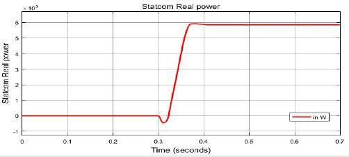
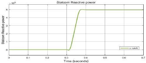
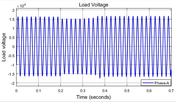
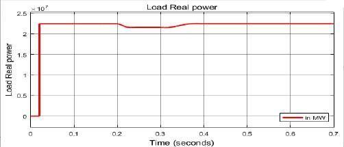
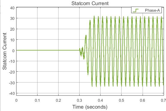
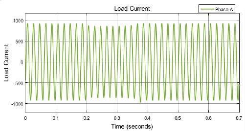
Fig 8.3.4
Attimet=0sec,therealpowerdrawnfromthesourceis27 reducingsourcetheMWaftertheconnectionstatcomtherealpowerdrawnfromsourceisreducedto29MW.Theexcesspowerfromtheafter0.3secondsisabsorbedbythestatcombyvoltageacrossthedccapacitor.
Fig 9.1.4 SourceReactivePower
Attimet=0sec,thecurrentdrawnfromsourceisatnormal reducemadevoltage.value,att=0.2secthereisincreaseinvalueduetoincreaseinAfter0.3sec,thestatcomconnectiontothesystemthesystemtodrawmorecurrentthanitrequirestothevoltageacrosstheload.
©
Certified Journal | Page1610
Fig 9.1.1 SourceVoltage
Attimet=0sec,thevoltageofthesourceisat1p.u.After 0.2 sec,thevoltageisincreasedfromits1p.uto1.02p.u.it canbeobservedfromtheabovewaveform.Thestatcomis madetoconnectatt=0.3sectoreduceexcesspowerdrawn bythesource.
Itisobservedfromthewaveformthatatt=0sec,theloadis supplyingpowerstatcomFrom0.3powerdrawingitsrequiredpower.After0.2secthereisdecreaseinduetodecreaseinvoltage,thestatcomconnectedatsecmakestheloadtodrawthedesiredreactivepower.thewaveformsoftheFigure8itisobservedthattheisabletocompensateboththeactiveandreactivebyactingstatcomasinthecapacitivenaturebothactiveandreactivepowerfromthesupply.
International Research Journal of Engineering and Technology (IRJET) e ISSN: 2395 0056 p ISSN: 2395 0072Volume: 09 Issue: 01 | Jan 2022 www.irjet.net
As there will be variations in the voltage of the transmissionsystemitissimulatedintheSimulinkby using programmablevoltagesource,whereitisprogrammedto itvoltagefrom1p.uvoltageto1.2p.uvoltageresultsinthe voltage swell at time of 0.3 seconds. The increase in the voltage can be observed fromthepowerwaveformsofthe Source. The statcom is connected to the transmission systematthe 0.5secondstodecreasethevoltageatloadto 1.2p.ufromthe1p.ubytheproperactiontakenbystatcom.
Fig 9.1.2 SourceCurrent
LoadReactivePower
byexpower15Attimet=0sec,thereactivepowerdrawnfromthesourceisMVAR,afterconnectionofstatcomat0.3secthereactivedemandbytheloadisincreasedby1MVAR.Thecesspowerfromthesourceafter0.3secondsisabsorbedthestatcombyreducingvoltageacrossthedccapacitor. 2021, IRJET | Impact Factor value: 7.529 | 9001:2008
ISO
4. 2. 2 Voltage Swell
Fig 9.1.3 SourceRealPower
madestatcomp.utimeAttimet=0sec,thestatcomvoltageisatvalueof1p.uWhenreaches0.2sec,thereisincreaseinthevoltageto1.02withtheincreaseofthevoltage.Attimet=0.3sec,theismadetoconnectandthevoltageacrosstheloadistobringtothe1p.u.
ctive power not demanded by the loadtomaintainitvaluenormalto1p.u.
Fig 9.3.2 LoadCurrent
Fig 9.2.3 StatcomRealPower
Initially the voltage across the load is maintained at 1 p.u value,after0.2secduetoincrementinsourcevoltagethereis increaseinvoltagevaluefrom1p.uto1.02p.u.Att=0.3sec statcomisconnectedtobringbackthevoltageto0.3sec.
Certified Journal | Page1611
Attimet=0sec,thestatcominclosedposition.Aftert=0.3sec, the statcom is made to connect to the load to absorb the maintainrequiredamountofrealpowernotdemandedbytheloadtoitvaluenormalto1p.u.
Fig 9.2.2 StatcomCurrent
Fig 9.2.1 StatcomVoltage
©
Attimet=0sec,asthevoltageacrosstheloadismade1p.u theloaddrawstherequiredamountofcurrent.Asthereis increase in voltage at 0.2 sec, there is increase in value of current.At0.3sec,thestatcomis madetoconnecttoload makestheloadtodrawtherequiredamountofcurrent. 2021, IRJET | Impact Factor value: 7.529 | ISO 9001:2008
International Research Journal of Engineering and Technology (IRJET) e ISSN: 2395 0056 p ISSN: 2395 0072Volume: 09 Issue: 01 | Jan 2022 www.irjet.net
Attimet=0sec,thepowersuppliedbystatcomismadeto zero,whenthereisincrementinvoltageatloadatt=0.3sec thestatcommakestheappropriatecontrolactiontoabsorb required amount of power to supply desired amount to load.
Fig 9.2.4 StatcomReactivePower
Fig 9.3.1 LoadVoltage
Attimet=0sec,thestatcominclosedposition.Aftert=0.3 requiredsec,thestatcomismadetoconnecttotheloadtoabsorbtheamountofrea
Journal | Page1612
Itisobservedfromthewaveformthatatt=0sec,theloadis indrawingitsrequiredpower.After0.2secthereisincrementpowerduetoincreaseinvoltage,thestatcomconnectedat 0.3 maintainabsorbingpowerstatcomFromsecmakestheloadtodrawthedesiredreactivepower.thewaveformsoftheFigure9itisobservedthattheisabletocompensateboththeactiveandreactivebyactingstatcomasintheinductivenaturebybothactiveandreactivepowerfromthesupplytotheconstantvoltageacrosstheload.
International Research Journal of Engineering and Technology (IRJET) e ISSN: 2395 0056 p ISSN: 2395 0072Volume: 09 Issue: 01 | Jan 2022 www.irjet.net
fromtheSource.voltagevoltagevoltageprogrammablevoltagesource,whereitisprogrammedtoitfrom1p.uvoltageto0.98p.uvoltageresultsinthesagattimeof0.3seconds.ThedecreasedinthecanbeobservedfromthepowerwaveformsoftheThestatcomisconnectedtothetransmissionsystemat0.5secondstoincreasethevoltageatloadto0.98p.uthe1p.ubytheproperactiontakenbystatcom.
4. 3. 1 Voltage Sag
Fig 10.1.2 SourceCurrent
LoadReactivePower
Fig 9.3.3
Attimet=0sec,thecurrentdrawnfromsourceisatnormal value,att=0.2secthereisdecreaseinvalueduetodecrease madeinvoltage.After0.3sec,thestatcomconnectiontothesystemthesystemtodrawlesscurrentthanitrequires.
Fig 9.3.4
4. 3 When under R Load ARCloadof100MVAconsistingof70MWofresistive areie..,loadloadisconsideredtobeasaload.TheSTATCOMoperationatsidefordifferentconditionssuchasdecreaseinvoltagevoltagesagandincreaseinthevoltageie..,voltageswelltobetested.
Fig 10.1.3 SourceRealPower
Attimet=0sec,therealpowerdrawnfromthesourceis15 seconds.bytheMWaftertheconnectionstatcomtherealpowerdrawnfromsourceisreducedto14MW.Therealpowerdemandedtheloadissuppliedbythestatcomaftertimet=0.3
LoadRealPower
Fig -10.1.1-SourceVoltage
As there will be variations in the voltage of the transmissionsystemitissimulatedintheSimulinkbyusing
Attimet=0sec,thevoltageofthesourceisat1p.u.After 0.2 sec,thevoltageisreducedfromits1p.uto0.98p.u.it canbeobservedfromtheabovewaveform.Thestatcomis madetoconnectatt=0.3seconds.
© 2021, IRJET | Impact Factor value: 7.529 | ISO 9001:2008 Certified
Itisobservedfromthewaveformthatatt=0sec,the load is drawing its required power. After 0.2 sec there is increase in power due to increase in voltage, the statcom power.connectedat0.3secmakestheloadtodrawthedesiredreal
reductionpower12Attimet=0sec,thereactivepowerdrawnfromthesourceisMVAR,afterconnectionofstatcomat0.3secthereactivedemandbytheloadisreducedby11MVAR.Thepowersupplyiscompensatedbythestatcom.
© 2021,
Fig 10.2.3 StatcomRealPower
Attimet=0sec,thestatcominclosedposition.Aftert=0.3
Attimet=0sec,thestatcominclosedposition.Aftert=0.3sec, thestatcom is made toconnect to theloadto producethe required amount of real power demanded by the load to maintainitvaluenormalto1p.u.Thestatcomdeliversreal powerbyincreasingthevoltageacrossthedccapacitorand byproducingvoltagewaveformleadingbyananglegreater thanthesupplyvoltage.
Fig 10.2.4 StatcomReactivePower
Fig -10.3.1-LoadVoltage
Fig 10.2.2 StatcomCurrent
|
Fig 10.1.4 SourceReactivePower
Fig 10.2.1 StatcomVoltage
madestatcomp.utimeAttimet=0sec,thestatcomvoltageisatvalueof1p.uWhenreaches0.2sec,thereisdecreaseinthevoltageto0.98withthereductionofthevoltage.Attimet=0.3sec,theismadetoconnectandthevoltageacrosstheloadistobringtothe1p.u.
Attimet=0sec,thepowersuppliedbystatcomismadeto zero, when there is reduction voltage at load at t=0.3 sec thestatcommakestheappropriatecontrolactiontosupply requiredamountofpowertoload.
Certified Journal | Page1613
Initially the voltage across the load is maintained at 1 p.u statcomreductionvalue,after0.2secduetoreductioninsourcevoltagethereisinvoltagevaluefrom1p.uto0.98p.u.Att=0.3secisconnectedtobringbackthevoltageto0.3sec.The it IRJET Impact Factor value: 7.529 9001:2008
capacitor.reactivemaintainrequiredsec,thestatcomismadetoconnecttotheloadtoproducetheamountofreactivepowerdemandedbytheloadtoitvaluenormalto1p.u.Thestatcomproducespowerbyincreasingthevoltageacrossthedc
| ISO
International Research Journal of Engineering and Technology (IRJET) e ISSN: 2395 0056 p ISSN: 2395 0072Volume: 09 Issue: 01 | Jan 2022 www.irjet.net
Attimet=0sec,thecurrentdrawnfromsourceisatnormal reducemadevoltage.value,att=0.2secthereisincreaseinvalueduetoincreaseinAfter0.3sec,thestatcomconnectiontothesystemthesystemtodrawmorecurrentthanitrequirestothevoltageacrosstheload.
Journal | Page1614
Attimet=0sec,asthevoltageacrosstheloadismade1p.u theloaddrawstherequiredamountofcurrent.Asthereis reductioninvoltageat0.2sec,thereisreductioninvalueof current.At0.3sec,thestatcomis madetoconnecttoload makestheloadtodrawtherequiredamountofcurrent.
Itisobservedfromthewaveformthatatt=0sec,theloadis 0.3powerdrawingitsrequiredpower.After0.2secthereisdecreaseinduetodecreaseinvoltage,thestatcomconnectedatsecmakestheloadtodrawthedesiredreactivepower.FromthewaveformsoftheFigure10itisobservedthatthestatcomisabletocompensateboththeactiveand
fromatSource.voltagevoltagevoltageprogrammablesystemAstherewillbevariationsinthevoltageofthetransmissionitissimulatedintheSimulinkbyusingvoltagesource,whereitisprogrammedtoitfrom1p.uvoltageto1.2p.uvoltageresultsintheswellattimeof0.3seconds.TheincreaseinthecanbeobservedfromthepowerwaveformsoftheThestatcomisconnectedtothetransmissionsystemthe0.5secondstodecreasethevoltageatloadto1.2p.uthe1p.ubytheproperactiontakenbystatcom.
supplyingreactivepowerbyactingstatcomasinthecapacitivenaturebothactiveandreactivepowerfromthesupply.
International Research Journal of Engineering and Technology (IRJET) e ISSN: 2395 0056 p ISSN: 2395 0072Volume: 09 Issue: 01 | Jan 2022 www.irjet.net powersupplybythestatcommadetheloadvoltagebackto initialvaluewhichis1p.u.
Attimet=0sec,thevoltageofthesourceisat1p.u.After 0.2 madecansec,thevoltageisincreasesfromits1p.uto1.02p.u.itbeobservedfromtheabovewaveform.Thestatcomistoconnecttoloadat0.3seconds.
© 2021, IRJET | Impact Factor value: 7.529 | ISO 9001:2008 Certified
Fig 11.1.1 SourceVoltage
Fig 10.3.4
LoadRealPower
4. 3. 2 Voltage Swell
Fig 10.3.3
Fig 11.1.2 SourceCurrent
Fig 11.1.3 SourceRealPower
Fig 10.3.2
Itisobservedfromthewaveformthatatt=0sec,theloadis drawingitsrequiredpower.After0.2secthereisdecreasein powerduetodecreaseinvoltage,thestatcomconnected at 0.3secmakestheloadtodrawthedesiredrealpower.
LoadCurrent
LoadReactivePower
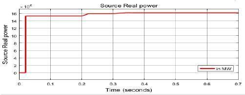
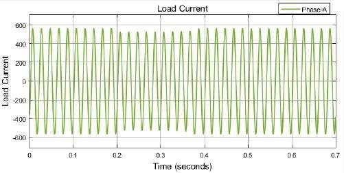
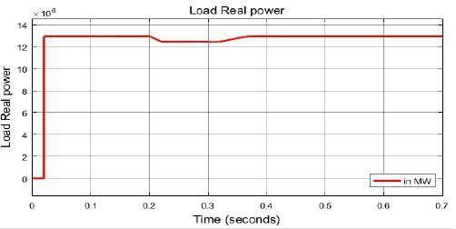
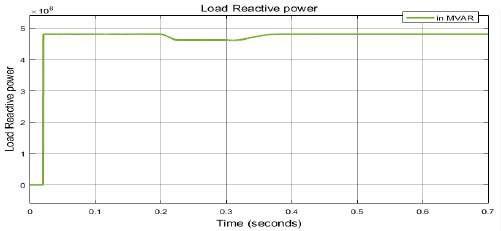
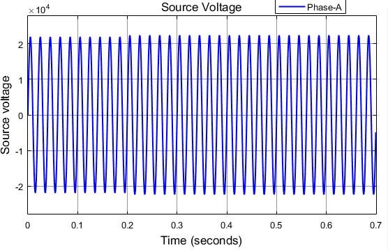
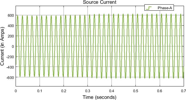
Fig 11.2.1
Attimet=0sec,thestatcomvoltageisatvalueof1p.uWhentimereaches0.2sec,thereisincreaseinthevoltageto1.02p.uwiththeincreaseofthevoltage.Attimet=0.3sec,thestatcomismadetoconnectandthevoltageacrosstheloadismadetobringtothe1p.u.
Attimet=0sec,thestatcominclosedposition.Aftert=0.3sec, the statcom is made to connect to the load to absorb the voltagemaintainrequiredamountofrealpowernotdemandedbytheloadtoitvaluenormalto1p.u.itismadebyreducingtheacrossthecapacitorvoltage.
Certified Journal | Page1615
StatcomVoltage
Initially the voltage across the load is maintained at 1 p.u theabsorbstatcomstatcomreductionvalue,after0.2secduetoreductioninsourcevoltagethereisinvoltagevaluefrom1p.uto1.02p.u.Att=0.3secisconnectedtobringbackthevoltageto0.3sec.Thereducesthevoltageacrossthedccapacitortothepowerfromthesourcecausedduetoincreaseinsourcevoltage. 2021, IRJET | Impact Factor value: 7.529 | ISO 9001:2008
Fig 11.2.2 StatcomCurrent
power15Attimet=0sec,thereactivepowerdrawnfromthesourceisMVAR,afterconnectionofstatcomat0.3secthereactivedemandbytheloadisreducedby1MVAR.
©
Fig 11.2.4 StatcomReactivePower
Attimet=0sec,therealpowerdrawnfromthesourceis15 theMWaftertheconnectionstatcomtherealpowerdrawnfromsourceisreducedto16MW.
Attimet=0sec,thepowersuppliedbystatcomismadeto zero,whenthereisreductionvoltageatloadatt=0.3secthe statcommakestheappropriatecontrolactiontoabsorbthe requiredamountofpowerfromtheload.
Fig 11.2.3 StatcomRealPower
International Research Journal of Engineering and Technology (IRJET) e ISSN: 2395 0056 p ISSN: 2395 0072Volume: 09 Issue: 01 | Jan 2022 www.irjet.net
Attimet=0sec,thestatcominclosedposition.Aftert=0.3 thetorequiredsec,thestatcomismadetoconnecttotheloadtoabsorbtheamountofreactivepowernotdemandedbytheloadmaintainitvaluenormalto1p.u.itismadebyreducingvoltageacrossthecapacitorvoltage.
Fig 11.3.1 LoadVoltage
Fig 11.1.4 SourceReactivePower
International Research Journal of Engineering and Technology (IRJET) e ISSN: 2395 0056 p ISSN: 2395 0072Volume: 09 Issue: 01 | Jan 2022 www.irjet.net
Fig 11.3.3 LoadRealPower
5. CONCLUSION Intheproposedcontrol strategytheD Qaxis controlis used to generate the gate pulses for the Diode clamped multilevel inverter. The statcom is tested for the different test conditions such as increase in the voltage ie.., voltage swell which is from 1 p.u to 1.02 p.u and decrease in the voltageie..,voltagesagwhichisfrom1p.uto0.98p.u.The results of MATLAB/SIMULINK waveforms shows the STATCOMwiththeintegrationofmultileveltopologyisableto takeappropriateactiontobringthevoltagetothenormaland to supply both real and reactive power with the less harmoniccontentintheoutputwaveforms.
[4] Mrs. Manisha patel, Divyesh S.Patel;MontyJ.Chapadiya; Kevin K. Naik; Bhavik K.Patel,” Reactive power compensation using STATCOM” Volume: 04, Issue: 04 2017,IRJET.
[8] Zhong Du; Tolbert, L.M.; Chiasson, J.N.; Ozpineci, B., "A cascade multilevel inverter using a single DC source," Applied Power Electronics Conference and Exposition, 2006. APEC '06. Twenty First Annual IEEE, vol., no., pp.5pp.,,19 23March2006.
Itisobservedfromthewaveformthatatt=0sec,theloadis 0.3powerdrawingitsrequiredpower.After0.2secthereisincreaseinduetoincreaseinvoltage,thestatcomconnectedatsecmakestheloadtodrawthedesiredreactivepower.FromthewaveformsoftheFigure11itisobservedthatthestatcomisabletocompensatebothactiveandreactivepowerinductivenaturebyabsorbingbothactiveandreactivepowerfromthesupplytomaintaintheconstantvoltageacrosstheload.
Itisobservedfromthewaveformthatatt=0sec,the load is drawing its required power. After 0.2 sec there is increaseinpowerduetoincrementinvoltage,thestatcom power.connectedat0.3secmakestheloadtodrawthedesiredreal
[2] Meenakshi Rastogi, Abdul Hamid Bhat and Aijaz Ahmad,” Simultaneous active and reactive power compensationusingSTATCOM”, Vol. 4, No. 4, 2018 [3] Mudasir Hussain Sheikh1, Navdeep Kaur Brar2,” POWER QUALITY IMPROVEMENT IN DISTRIBUTION POWER SYSTEM USING STATCOM”, Volume: 07 Issue: 02 , 2020, IRJET.
Fig -11.3.2-LoadCurrent
[7] Reference book: “FACTS CONTROLLERS IN POWER TRANSMISSION AND DISTRIBUTION”, K. R. Padiyar Department of Electrical Engineering Indian Institute of ScienceBangalore 560012India.
Fig 11.3.3 LoadReactivePower
[6] N. G. Hingorani and L. Gyugyi, “Understanding FACTS ConceptsandTechnologyofFlexibleACTransmission Systems,” 1st Indian Edition, IEEE Press, New York and StandardPublishersDistributors,Delhi,2000.
[5] Pierre Giroux, Gilbert Sybille, Hoang Le Huy, “Modeling and Simulation of a Distribution STATCOM using Sirnulink’s Power System Blockset,” IECONOl: The 27th Annual Conference of the IEEE Industrial Electronics Society
Attimet=0sec,asthevoltageacrosstheloadismade1p.u theloaddrawstherequiredamountofcurrent.Asthereis increase in voltage at 0.2 sec, there is increase in value of current.At0.3sec,thestatcomis madetoconnect toload makestheloadtodrawtherequiredamountofcurrent.
REFERENCES [1] Bindeshwar Singh, K.S. Verma, Deependra Singh, C.N. Singh, Archana Singh, Ekta Agarwal, Rahul Dixit, Baljiv Tyagi, “Introduction of FACTS controllers, a critical review”,InternationalJournalofreviewsincomputing, Vol.8,31stDecember2011
[9] Pieree giourux; Hoangle Huayn, “Modelling and simulation of a distribution STATCOM using Simulink's Power System Block set”, Conference: Industrial ElectronicsSociety,2001.IECON'01.The27thAnnual ConferenceoftheIEEE,Volume2 © 2021, IRJET | Impact Factor value: 7.529 | ISO 9001:2008 Certified Journal | Page1616