1: Descriptionsof
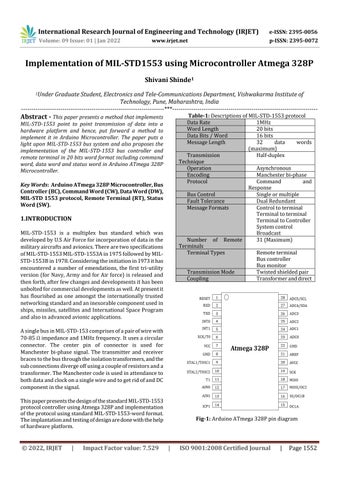
STD 1553protocol DataRate 1MHz WordLength 20bits DataBits/Word 16bits MessageLength 32 data words (maximum) TechniqueTransmission Half duplex Operation Asynchronous Encoding Manchesterbi phase Protocol Command and Response BusControl Singleormultiple FaultTolerance DualRedundant MessageFormats Controltoterminal Terminaltoterminal TerminaltoController System Broadcastcontrol Number of Remote Terminals 31(Maximum) TerminalTypes Remoteterminal Buscontroller Busmonitor TransmissionMode Twistedshieldedpair Coupling Transformeranddirect Fig 1: ArduinoATmega328Ppindiagram
1Under Graduate Student, Electronics and Tele Communications Department, Vishwakarma Institute of Technology, Pune, Maharashtra, India *** Abstract This paper presents a method that implements MIL STD 1553 point to point transmission of data into a hardware platform and hence, put forward a method to implement it in Arduino Microcontroller. The paper puts a light upon MIL STD 1553 bus system and also proposes the implementation of the MIL STD 1553 bus controller and remote terminal in 20 bits word format including command word, data word and status word in Arduino ATmega 328P Microcontroller.
Key Words: Arduino ATmega 328P Microcontroller, Bus Controller (BC), Command Word (CW), Data Word (DW), MIL STD 1553 protocol, Remote Terminal (RT), Status Word (SW).
International Research Journal of Engineering and Technology (IRJET) e ISSN: 2395 0056 Volume: 09 Issue: 01 | Jan 2022 www.irjet.net p ISSN: 2395 0072
Journal | Page1552
MIL STD 1553 is a multiplex bus standard which was developedbyU.SAirForceforincorporationofdatainthe militaryaircraftsandavionics.Therearetwospecifications ofMIL STD 1553MIL STD 1553Ain1975followedbyMIL STD 1553Bin1978.Consideringtheinitiationin1973ithas encountered a number of emendations, the first tri utility version(forNavy,ArmyandforAirforce)isreleasedand thenforth,afterfewchangesanddevelopmentsithasbeen unboltedforcommercialdevelopmentsaswell.Atpresentit has flourished as one amongst the internationally trusted networkingstandardandaninexorablecomponentusedin ships,missiles,satellitesandInternational SpaceProgram andalsoinadvancedavionicapplications. AsinglebusinMIL STD 153comprisesofapairofwirewith 70 85Ωimpedanceand1MHzfrequency.Itusesacircular connector. The center pin of connector is used for Manchester bi phase signal. The transmitter and receiver bracestothebusthroughtheisolationtransformers,andthe subconnectionsdivergeoffusingacoupleofresistorsanda transformer.TheManchestercodeisusedinattendanceto bothdataandclockonasinglewireandtogetridofandDC componentinthesignal. ThispaperpresentsthedesignofthestandardMIL STD 1553 protocolcontrollerusingAtmega328Pandimplementation oftheprotocolusingstandardMIL STD 1553 wordformat. Theimplantationandtestingofdesignaredonewiththehelp ofhardwareplatform.
1.INTRODUCTION
Implementation of MIL-STD1553 using Microcontroller Atmega 328P Shivani Shinde
Table MIL
© 2022, IRJET | Impact Factor value: 7.529 | ISO 9001:2008 Certified
1


EarlierMIL STD 1553Awastheonlymodelintroducedbut to overcome its limitations MIL STD 1553B model was introduced. The previous model did not comprise of a broadcast option but the later version had the broadcast optionwhichisrequiredforbroadcastingofmessagesnot onlyto bus controllers but alsotoother remoteterminals andthebusmonitor.
Fig 2:ManchesterIIBi PhaseLevelEncoding B. Word Formats:
SYSTEM OVERVIEW AsdiscussedintheliteraturereviewMIL STD 1553protocol has Bus controller and Remote terminal. According to the designofMIL STD 1553therecanbe31differentRemote terminalsandBusterminalswhichisusedforperforming differenttasksandforcontrollingaparticularactivity.For transferringofdataisoperatedusingdataword.
International Research Journal of Engineering and Technology (IRJET) e ISSN: 2395 0056 Volume: 09 Issue: 01 | Jan 2022 www.irjet.net p ISSN: 2395 0072
MIL STD 1553 controller comprises of bus terminal and remote controller. Based on Bus controller and Remote terminalsixtypesoftransactionsareallowed.Thismainly includesBuscontrollertoRemoteterminal,Remoteterminal toBuscontrollerandRemoteterminaltoRemoteterminal word transfer. Bus controller over the bus, it initiates messagecommunication.Remoteterminalmainlyprovides aninterfacebetweenthedatabusandthesub system,alsoit createsabridgebetweenonebustoanother.Busmonitor workslikeaserver.Itmainlymonitorsandrecordsallthe bus transactions. Atmega 328P is a very basic single chip microcontroller developed by Atmel. It has a modified HavardArchitectureand8 bitRISCprocessorcore.Themain reasonbehindchoosingthismicrocontrollerisithas23I/O pinsandcanworkat1MHzfrequencyrequiredfortheMIL STD 1553 protocol. In this paper we have mainly tried to explaintheBuscontrollertoRemoteterminalwordtransfer inAtmega328P 3.
A. Bus Protocol: MIL 1553messagesonbusaccommodatemorethan16 bit words,thatareclassifiedascommandword,datawordand the status word. Every word is always leaded up by 3μs synchronizationpulseandisalwaysaccompaniedbyanodd party bit. Since, the 3μs synchronization pulse consists of 1.5μslowandaccompaniedby1.5μshighpulseManchester bi phase signal is used for the working of this protocol. Around4μsgapisplacedbetweentoconsecutivemessages. If a particular device exceeds the time of 14μs then, it is considered that the command message is not received by thatdevice.
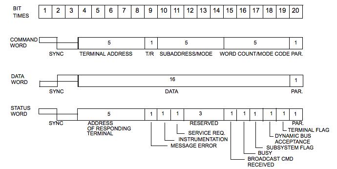
Every word comprises of a unique format within the ordinary structure. Each word is 20 bits in length who’s preceding 3 bits are synchronization bits, which basically sanctions the decoding clock for resynchronization at the startofeachword.Thenext16 bitscontainthedatatobe transmittedandthelastbitisparitybitwhichalwaysanodd parity for a single word. All encoding of bit is built upon Manchester Bi phase encoding format. It provides a self clocking waveform. The signals produced are mainly symmetricalaboutzero.Alogicof0and1ismainlybased upon transition between positiveandnegativelevels.It is logic 0 from negative to positive and 1 from positive to negative. The dedicated waveforms can be understood by thefigure.2.
© 2022, IRJET | Impact Factor value: 7.529 | ISO 9001:2008 Certified Journal | Page1553
2. LITERATURE REVIEW
Table 2:Input/outputdescriptionofEncoder S. No Parameter Input/Output Description 1 clk Input 2MHz 2 rst Input 1clockcycle 3 start Input 2clockcycles 4 cmd_data Input Cmdordatasync 5 info Input 16 bithexdata 6 man enc Output Serial encodingManchester 7 busy Output Indicatestheendof encodingManchester

Fig-3: WordFormatforMIL STD 1553
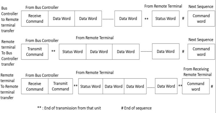
Fig 4: WordTransferMIL STD 1553
b. Data Word: Thefirst3bitusuallyaresynchronizationbitsandthenext 16 bitscontaintheactualdatatobetransmittedandthelas bitisoddparitybitasexplainedinfigure.3.
ThenextbitwhichisservicerequestbitisusedtoinformBC byterminalthatitneedstobereceived.Bits12,13and14 arereservedbitsforfutureuse.Bit16isabusybitthattells iftheterminalismovedataornottootherterminals.Bits17 and19areflagbits.Bit18definesifterminalhasreceived thewordcodeandhasacceptedbuscontrolandthelastbit isparitybitwhichisoddparityasexplainedinfigure.3.
International Research Journal of Engineering and Technology (IRJET) e ISSN: 2395 0056
4. Methodology
5. Design and Implementation
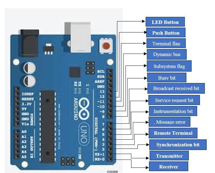
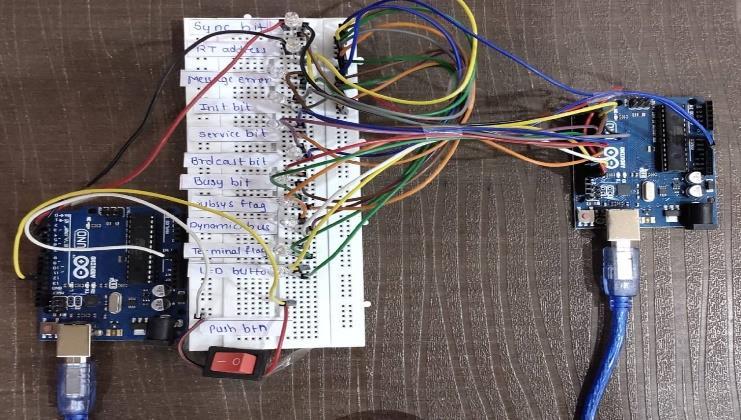
ThemessagetransferisbasedonMilStd1533protocoland communicationisobtainedusing2ArduinoATmega328P microcontroller.Herewearebasicallyconstructingalibrary forArduinoATmega328PbasedonMilStd1533protocol. ThedigitalpinsofArduinoATmega 328Pareusedtobuild thecommunication.OneoftheArduinoactsasatransmitter andtheotheractsasareceiver.sothepinconfigurationis explainedinfigure.5.Thesynchronizationpin,transmitter, receiver, remote terminal, message error, reserved, instrumentationbit,servicerequestbit,Broadcastreceived bit, busy bit, flags, dynamic bus control accept pins are definedandaddressisgeneratedusingthesepins.byusing thesynchronization,remoteterminalandotherpins20 bit commandwordisgenerated.Asthedatawordofmil1553is transmittedbyHexcodingthedatawordisconstructedby convertingastringintoahexaddressandtransmittedand thenconvertedbackintostringwhilereceiving.Whenthe datawordisreceivedthemessageerrorbit,instrumentation bit,reservedbit,servicerequestbit,broadcastbit,busybit, flags,dynamicbuscontrolacceptpinsaremadehighanda statuswordisgenerated.FirstisBCtoRTandthenextoneis RT to BC. All of these transfers happen according to the predefined format of the 1553 protocol. In this type of transfer the bus controllers sends the command word, followed by the data word and when the data word is received by terminal the terminal sends the status word backtothecontroller.Thedesignisdoneaftertakinginto considerationtheworkingandneedsofthe1553protocolas mentionedinthesystemstructure.Hardwareisdesignedas showninfigure.6.
a. Command Word: ACommandWordutilizesthefirst3 bitsassynchronization bits.Thenext5 bitsfortheaddressoftheRT.Thenextbitis transmit/receive (1 for Transmit and 0 for receive). The proceeding 5 bits specifies the sub address or mode code bits.Thenext5 bitsaredefinedas WordCount bits. They definethewordcountofthetasktobeperformedandthe lastbitisparitybitwhichalways definedasoddparity as explainedinfigure.3.
Volume: 09 Issue: 01 | Jan 2022 www.irjet.net p ISSN: 2395 0072
© 2022, IRJET | Impact Factor value: 7.529 | ISO 9001:2008 Certified Journal | Page1554
The main method which we have implemented is Bus controllertoRemoteterminaltransferofdataword.Inthis type of transfer the bus controllers sends the command word,followedbythedatawordandwhenthedatawordis received by terminal the terminal sends the status word back to the controller. In the Remote terminal to Bus controllertransfer,thecontrollersendsacommandword. TheRTaftergettingcommandwordsendsthestatusword inadditiontothedatawordspecified.Inremoteterminalto remoteterminaltransfercommandwordissendtoanother terminal.Oncethecommandwordisreceivedstatuswordis sendfollowedbythedataword.
c. Status word: The first 3 bits of the status word are also the synchronization bits. The proceeding 5 bits are Terminal address.Thenextbitdefinesthemessageerrorbit,whichis setbyterminalwhenanerrorisdetected.Messageerrorbit isproceededbyinstrumentationbitwhichisalwayssetto0.
International Research Journal of Engineering and Technology (IRJET) e ISSN: 2395 0056 Volume: 09 Issue: 01 | Jan 2022 www.irjet.net p ISSN: 2395 0072 © 2022, IRJET | Impact Factor value: 7.529 | ISO 9001:2008 Certified Journal | Page1555 Fig-5: DesignofMIL STD 1553onATmega328P Fig-6: HardwaredesignofMIL STD 1553
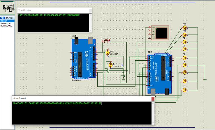
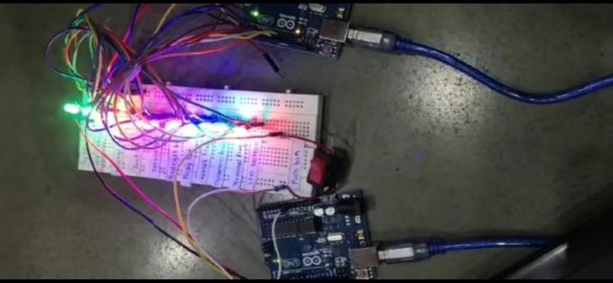
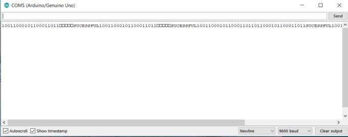
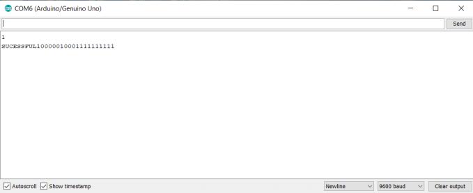
6. Result WehavetestedtheprotocolinProteusasseeninfigure.6. andalsoreceivedtheresultsbyactuallyimplementingitin hardwarethedetailedresultsareshowninfigure.7.figure.8. figure.9. and figure.10. To show which pins get in active mode while the communication we have used Led bulbs assurethattheonlyrequiredpinsareworkingandweare gettingtheoutput.
Fig 8: HardwaretestingofMIL STD 1553
7. Future Scope and Conclusion In this growing world of development in Artificial IntelligenceandotherfieldsMIL STD 1553playsavitalrole. Implementation of MIL STD 1553 in other AVR microcontrollerscanhelpinautomationandadvancementof commercial applications. Development of more advanced librariesbasedonMIL STD 1553hasbecomeanecessityas theworldismovingtowardsautomation. This paper describes a new way to design MIL STD 1553 protocolusingATmega328PMicrocontroller.Sincemostof the1553implementationsareonFieldProgrammableGate Arrays which are nothing but semiconductor devices, we havedesignedtheCommunicationchannelbetweenthetwo Arduinos that follows MIL STD 1553 Protocol. We have testeditionproteussimulatoraswellasimplementedthe hardware.So,itisclearthatMIL STD 1553willcontinueto extend its application in more integrated fields and commercialapplicationstoo.
Fig 7: ProteusSimulationofMIL STD 1553
Fig 9: SimulationterminalresultofRemoteterminal Fig 10: SimulationterminalresultofBuscontroller
© 2022, IRJET | Impact Factor value: 7.529 | ISO 9001:2008 Certified Journal | Page1556
[5] ChenXiHui,LengXue,LiWenMing,ZhengLiNa,“The RemoteTerminalDesignandImplementationof1553B Based on DSP”, Changchun Institute of Optics, Fine Mechanics and Physics, Chinese Academy of Sciences China.
[4] Department of Defense Interface Standard for Digital TimeDivisionCommand/ResponseMultiplexDataBus, MIL STD 1553B, Notice 4, 1996. Washington, DC: DepartmentofDefense,1978.
[6] Michael Hegarty, Principal Marketing Engineer Data DeviceCorporation,"MIL STD 1553GoesCommercial” June,2010 [7] Design and Verification of MIL STD 1553B Remote Terminal Modules L. Karthik, K.V. Ramana Reddy, Dr. SivaYellampalli [8] MIL STD 1553DESIGNER’SGUIDE [9] ArduinoMicrocontrollerProcessingforEveryone!Third Edition Steven F. Barrett University of Wyoming, Laramie,WY
[1] MIL STD 1553(1990)Designer’sguide,3rdedn.Data DeviceCorporation,Bohemia,NewYork
[2] MIL STD 1553 tutorial by Condor Engineering, Inc., USA [3] MIL STD 1553tutorialbyAIMGmbH
References
International Research Journal of Engineering and Technology (IRJET) e ISSN: 2395 0056 Volume: 09 Issue: 01 | Jan 2022 www.irjet.net p ISSN: 2395 0072