ABSTRACT Nigeria power network has been facing voltage, steady state and transient stability problems with increasing load demand and high population growth. The major causes of power network instability include loading of the generators or tie line, power transfer capability of transmission lines, leading power factor operation of the generator and automatic voltage regulator(AVR)gain.Theobjectivesofthisworkinclude overview analysis of the existing Nigeria 10 generators 330kV, 28 bus power network without introduction of PSS model and develop a workable power network that can provide dynamic and transient voltage control during placement of PSS model in order to enhance the totalityofpowernetworkstability.Thepaperpresentsa cost effective and satisfactory design of power system stabilizers (PSS) capable of solving problems of voltage, network oscillatory instability and damping for generator rotor oscillations. The designed PSS are incorporated into two generators, 3 bus and 10 generators, 28 bus, 330kV Nigeria power network using MATLAB/SIMULINK Power System Toolbox (PSAT) program to evaluate voltage and network instability problems. The dynamic or voltage collapse stability results obtained from PSAT load flow analysis revealed thatthemaximumloadingpoints(MLP)forthenetwork with and without PSS are 10.1501 pu and 4.5674 pu respectively.
Akwukwaegbu, Isdore Onyema1, Obichere Jude-Kennedy Chibuzo2, Raymond Okechukwu Opara3 3
1
Certified Journal | Page1512
International Research Journal of Engineering and Technology (IRJET) e-ISSN:2395-0056
Volume:09Issue:01|Jan 2022 www.irjet.net p-ISSN: 2395-0072 © 2022, IRJET | Impact Factor value: 7.529 | ISO 9001:2008
Department of Electrical and Electronic Engineering, Faculty of Engineering, Federal University of Technology, Owerri, Nigeria. ***
KEYWORDS: Power System Stabilizers (PSS), Nigeria 28 bus power network, voltage problems, steady state problems, transient stability problems, instability problems, MATLAB/SIMULINK Power system Toolbox (PSAT)program,maximumloadingpoint(MLP).
PLACEMENT OF POWER SYSTEM STABILIZER (PSS) IN NIGERIA 28 BUS POWER NETWORK FOR EFFECTIVE VOLTAGE AND DYNAMIC STABILITIES EVALUATION
1INTRODUCTION
The behavior of synchronous machines following perturbationliesattheheartofthestabilitychallengein the power system. After a change in power, machines shouldreverttotheirformerconditionifitdoesn'talter. A new operational state is required whenever a change in load, generation, or network circumstances causes an imbalancebetweensupplyanddemand.Nomatterwhat happens, if the system is stable, all linked synchronous machines should be functioning at the same pace, in parallel, and in synchronism [1,2]. Even though synchronousmachinesandtielinestendtohavestability issues, other types of power systems with large capacitances may also have instability. Arrangements must be taken to avoid damaging equipment and self excitation of machinery by avoiding high voltages under light load situations. Modern synchronous generators requirehigh performance excitationsystemsinorderto maintainsteady stateandtransientstability.Instabilities causedbypowersystemdisturbancescanleadtosystem shutdowns. In the event of disruptions, such as three phase faults, loss of generators, loss of lines, and loss of loads, stabilizing measures or controls must be implemented in the power network to optimize system performance.Theenergysupplysectorhashaditswork cutoutforitwhenitcomestostabilizingandimproving power system oscillators. 330kV Nigeria 28 bus power network electromagnetic oscillation stability issues may be addressed using an effective power system stabilizer Low(PSS).frequency power system oscillations were among thefirstissuesthataroseinpowersystems.Smallsignal stabilityinapowersystemiscompromisedbytheselow frequencyoscillations(LFOs),whichjeopardizeeffortsto maximize power transmission and secure the power system. The stability issue was put on hold for a while after the damper windings on the generator rotors and turbines were confirmed to be adequate. A poor synchronizing torque among the generators was shown to be a substantial contributor to system instability as power systems were operated closer to their stability limitations.Improvedsteady statestabilitywasachieved by the use of automatic voltage regulators (AVR). Concerns about long distance transmission lines emerged with the development of massive, interconnectedpowernetworks. Low frequency oscillations can be reduced by adding a supplemental controller to the control loop, such as the addition of power system stabilizers (PSS) to the AVRs on generator. Designed for a certain network topology and steady state circumstances, the power system stabilizers are excellent at their job. However, as the

© 2022, IRJET | Impact Factor value: 7.529 | ISO 9001:2008 Certified Journal | Page1513
I Inter area modes, in which generators located throughout a large geographic region participate. The oscillation frequencies are modest,rangingfrom0.2to0.5hertz(cyclesper second).
If the network can be reduced by retaining, only the internal buses of the generators and the losses in the reducednetworkcanbeneglected, ( ) (8) Where Xij isthe reactanceofthe elementconnectingthe generator buses i and j; Ei and Ej are the generator
system grows more crowded, its performance suffers With[3,4,5,6].the introduction of high speed exciters and continuously acting voltage regulators, the possibility to manage synchronous machine angular stability through the excitation system was discovered. Hydraulic and thermal equipment increasingly employ bus fed static exciters with thyristor controllers. Because of improvements in thyristor controllers, they have a strong initial reaction and better dependability A[7,8,9,10].powersystem analysis toolkit, MATLAB/SIMULINK, is used to model the voltage and dynamic stability of two generators, three bus and ten generators, 28 bus 330kV Nigeriapowernetworks(PSAT).
2. MATHEMATICAL ANALYSIS OF POWER SYSTEM STABILIZER (PSS)
International Research Journal of Engineering and Technology (IRJET) e-ISSN:2395-0056
Itispossibletoobtainthefollowingequation: PΔX=[A]ΔX (5) Where [ ] [ ( ) ] (6) The elements of A are functions of the operating point. Thestabilityoftheoperatingpointcanbejudgedbythe locationofthe eigenvalues ofthematrixA.Ifall thereal points of the eigenvalues are negative, the system is stable. If one or more has positive real parts, then the systemisunstable
Assuming that the classical model is used to represent thegeneratorsinamulti machinesystem,thelinearized systemequationsmaybeexpressedasfollows: [M] 2Δδ= [K]Δδ (7) Where [M] is diagonal matrix Mjj = 2Hj / ωB (Hj is the inertia constant of the jth synchronous machine). , where Pei is the power outputs of the ith machine, istherotorangleofjthmachinereferredtoa rotating reference frame (with the operating speed ω0).
Thevoltages.solutionofequation(7)isrepresentedas ∑ ( ) Where [ ] is the vector of relative angles ( , C1, … , Cm 1, d1, d2, … , dm 1 are scalars depending on the initial conditions, V1, Vm 1 are vectors. The structure of a vector Vj depicts the participationofvariousmachinesintheoscillationmode whose frequency is . For a ‘m’ machine system, there are (m 1) oscillatory modes whose frequency varies in the range of 0.2 to 3Hz. The frequencies are obtained as square rootsofthe non zeroand real eigenvaluesof the matrix[ ] [ ] The various modes of oscillation are grouped into three broadcategories[9]asfollows:
Volume:09Issue:01|Jan 2022 www.irjet.net p-ISSN: 2395-0072
Power plants can operate in intra plant modes, in which only the generators are involved. It is common for the oscillation frequencies to be ratherhigh,rangingfrom1.5to3.0Hz.
The concepts of stabilization in the power network is describedbyasetofnon lineardifferentialandalgebraic equationsasfollows[4,5]: PX=F(X,Z), P=d/dt s (1) Y=H(X,Z) (2) 0=G(Y,Z) (3) The oscillatory instability can be viewed as stability of the operating point, subjected to small, random perturbations which are always present. The analysis can be performed by linearizing the system equations aroundtheoperatingpoint(X=X0,Y=Y0,Z=Z0).Where Xarethestatevariables,Yrepresentactiveandreactive power injections (at buses), Z represent voltage magnitudesandanglesatvariousbuses.
XExpressing=X 0 +ΔX,Y=Y0 +ΔY,Z=Z0 +ΔZ (4)
Localmodes,inwhichanumberofgeneratorsin agivenregioncollaborate.Theoscillationsoccur at frequency ranging from 0.8 to 1.8 hertz (hertz).
Phase correction for the Power System Stabilizer [3] is basedonthefollowingcriteria:
b) The compensated phase lag at local mode frequency should be below 45o, preferably near 20o c) Thegainofthecompensatorathighfrequencies (this is proportional to ) should be minimized. The first requirement must be met in order to avoid instability of intra plant modes at higher frequencies in the future. Typically, the frequency range of interest is 0.1 to 2.0Hz, and the phase lead network should offer compensation throughout the whole frequency range of interest.(i)
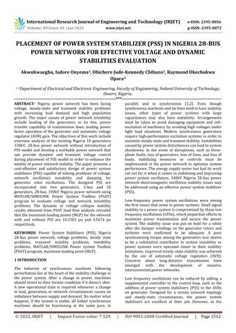
(ii) The stabilizer gain, denoted by the letter KSTAB, regulates the amount of damping thatisintroducedbythePSS.(3)Thegainis set to the value that corresponds to the greatestamountofdampening.
© 2022, IRJET | Impact Factor value: 7.529 | ISO 9001:2008 Certified
a) The compensated phase lag (phase of P(s) = GEP(s)PSS(s)) should pass through 90o at frequency around 3.5Hz. For frequency input signal,thiscanbereducedto2.0Hz.
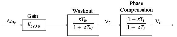
The signal washout block serves as a high pass filter, with the time constant Tw high enough to allow signals associated with oscillations in wr to pass unchanged. Washout it, steady changes in speed would modify the terminal voltage. It allows the PSS to respond only to changes in speed. The value of Tw is not crucial from the perspective of the washout function, and it can be anything between 1 and 20 seconds in duration. In particular, it must be long enough to allow stabilizing signals at the frequencies of interest to pass through intact, but not so long that it causes undesired generator voltage excursions duringsystem islandingsituations.
Fig.2:ThyristorexcitationsystemwithAVRandPSS.
Usingperturbedvalues,block4offigure2isconsidered tobemadeupoftwoblocks:
3. DESIGN AND IMPLEMENTATION OF POWER SYSTEMSTABILIZERS
Initsmostbasicform,apowersystemstabilizer(PSS)is a device that dampens the oscillations of a generator rotor by managing the excitation of the generator with supplementary stabilizing signals. A component of electricaltorqueinphasewiththerotorspeedvariations mustbeproducedbythestabilizerinorderforittooffer dampening.
The power system stability should be considered whenapplyingthePSStothepowernetwork,rather than merely the small signal stability, because the overallsystemstabilityshouldbeimproved[3].
The PSS is intended to enhance the amount of power that can be sent through a network, which is currently restricted by oscillatory instability. When the network is subjected to major disruptions such as the development of a three phase fault, the unexpected loss of a line, or the sudden application or removal of loads, the PSS must function effectively. The block diagram of the PSS design used in the power network is shown in figure1.Fig.1:Blockdiagramofpowersystemstabilizer. Power system stabilization is now presented using the thyristor excitation system, as seen in Fig 2, as a case study.TheAVRandpowersystemstabilizerareincluded in the excitation block diagram for correct modeling. In this study, small signal performance, stabilizer and exciter output limitations, and other parameters, are taken into consideration. Here's a quick rundown of the criteria that go into creating different power system stabilizersetups.
Journal | Page1514
International Research Journal of Engineering and Technology (IRJET) e-ISSN:2395-0056
Phase correction, signal washout, and gain blocks make upthepowersystemstabilizerseeninfigure2. (i) For the exciter to generator electrical (air gap) torque phase lag, the phase correction block gives the required phase lead characteristic. A singlefirst orderblockisshowninthediagram. It is possible to obtain the needed phase compensation by using two or more first order blocks. Second order blocks with complicated rootshavebeenemployedinseveralinstances.
Volume:09Issue:01|Jan 2022 www.irjet.net p-ISSN: 2395-0072
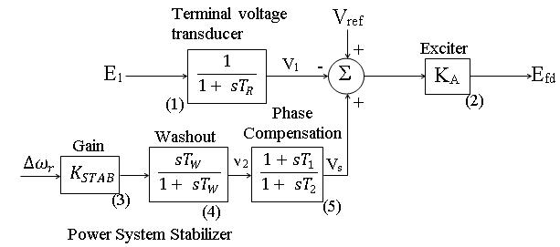
Inthiscase, becomesthestatevariable,(10)with andtheoutputΔV2 oftheblockisgivenby(11)
ThezeroofD(s)shouldlieinthelefthalfplane.Theycan be complex or real. Some of the zeros of N(s) can lie in therighthalfplanemakingitanon minimumphase.The timeconstants,T1 toT4 inequation(14)aretobechosen from the requirements of the phase compensation to achievedampingtorque. Thegainof PSSisto bechosen toprovideadequatedampingofall criticalmodesunder variousoperatingconditions. The different values of the centre frequency, fc the compensatorofequation(14)arecomputedby √ (16) Itisassumedthat (17) Theplanttransferfunction,GEP(s)iscomputedby (18) WhereVs istheoutputofthePSS
Power system stabilizer behavior is studied using the current 330kV, 28 bus, 10 generator Nigeria network. Niger's 28 node, 28 bus system has 10 generators and 18 load (PQ) buses; 16 transformers; 12,426MW grid capacityand5,988kmtransmissionlinesasseeninfig4. The lower reactance and smaller inertias between the two machines make it possible for the intra plant oscillations to have a greater frequency since they are linkedinparallel betweenthetwoproducingstationsin
To produce pure damping torque at all frequencies, the phase characteristics of the power system stabilizer (PSS) must, in the ideal case, balance the phase characteristicsofthegeneralpurposegenerator(GEP)at allfrequencies.Specifically, thephasecompensatorused inthisapplicationiscomposedoftwolead lagstatesand hasthefollowingtransferfunction. Where Ks is the gain of the PSS and the time constants, T1,toT4 arechosentoprovideaphaseleadfortheinput signal in the range of frequencies of interest (0.1 to 3.0 Hz). With static exciters, only one lead lag state may be adequate. In general, the phase compensator can be chosenwiththefollowingtransferfunction(15)
© 2022, IRJET | Impact Factor value: 7.529 | ISO 9001:2008 Certified Journal | 1515
Similarly,block5offigure2istreatedasfollows: Inthiscase, isthestatevariable,with (12) andtheoutput isgivenby ( ) (13)
Fig.3:Stabilizerwithspeedinput:systemblockdiagram.
The basis for the choice of the time constants of the phase compensator can be analysed with reference to the block diagram of the single machine system when PSSisaddedasshowninfigure3
N(s)Where:=1+a1s+a2s2 +…+apsp D(s)=1+b1s+b2s2 +…+bpsp
4. APPLICATION OF PSS TO NIGERIA POWER NETWORK
Page
Volume:09Issue:01|Jan 2022 www.irjet.net p-ISSN: 2395-0072
International Research Journal of Engineering and Technology (IRJET) e-ISSN:2395-0056
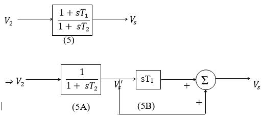
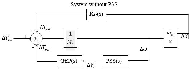
Fig.7:MATLAB/SIMULINKcircuitdesignfor investigatingvoltagestabilityof10generators28 bus NigeriapowernetworkwithPSSconnected.
5. RESULTSANDDISCUSSION
Using two generators connected in a three bus power networkwithoutapowersystemstabilizer,thetransient behavioroflinevoltage(kV),linepower(MW),angle(°), angular speed (ω), and reference voltage were demonstrated in Figures 8 and 9. The findings of the simulation for a two generator, three bus power network following the occurrence of a three phase failure revealed that the network is unstable in the absence of the use of a power system stabilizer. When the PSS design is connected to the network, the line power settles after 2.5 seconds, the angle after 4 seconds, the angular speed after 3 seconds, and the terminal voltage after 2.5 seconds, as illustrated in figures10to11,respectively.
Page1516
Figure4:Theexisting28bus330KVNigerian transmissiongrid.
Volume:09Issue:01|Jan 2022 www.irjet.net p-ISSN: 2395-0072
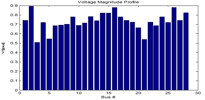
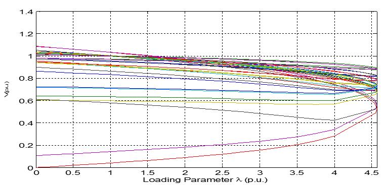
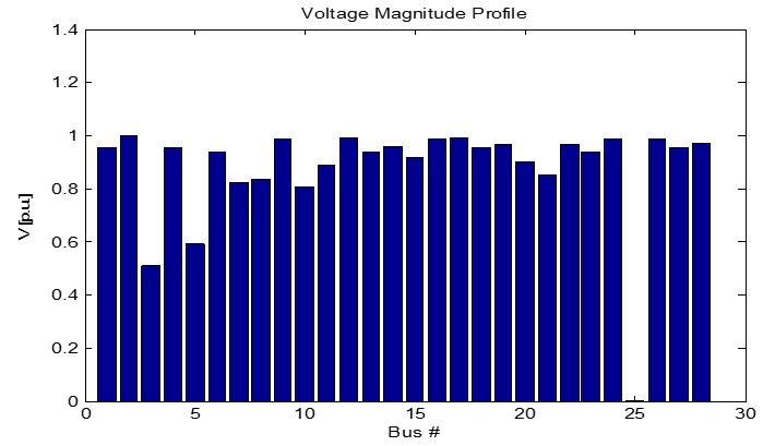
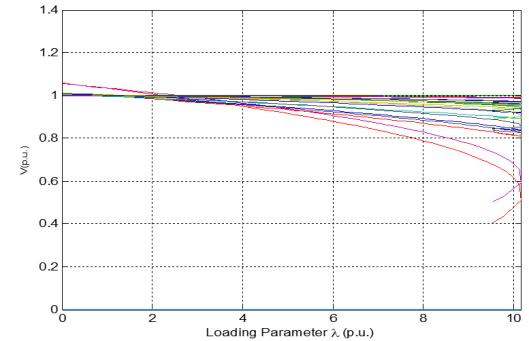
The 10 generators 28 bus power network with PSS recorded 14 low and high voltage violations with total power loading and maximum power factor values of 6.5585pu and 10.1501pu, whereas when this power network was not connected to a PSS, all buses of the network recorded voltage violations with total power loading and maximum power factor values of 2.9501pu and 4.5674pu, as shown in table 1 and figures 12 to 15, respectively.
Fig.5:Twogeneratingstations,3 buspowernetwork. The two generators located at Afam bus7 and Calabar bus 10 swing together during oscillation. A Power System Analysis Toolbox (PSAT) specialized tool in MATLAB environment is deployed for assessing the behavior of power system stabilizer of 2 generators 3 bus Nigeria power network. MATLAB/SIMULINK circuit designed using electrical blocks contained in the SIMULINK library for 2 generators 3 bus and 10 generators 28 bus Nigeria power networks connected withpowersystemstabilizersareillustratedinfigures6 and7respectively.
International Research Journal of Engineering and Technology (IRJET) e-ISSN:2395-0056
© 2022, IRJET | Impact Factor value: 7.529 | ISO 9001:2008 Certified | Nigeria's 3 bus power network. Afam and Calabar are thelocationsofthetwogenerators.AtAlaojibus23,fig5 shows the two generator buses connected to each other atAfamand Calabarbuses 7and10and thelinelinking bus bars.TherearetwogeneratorsatAfambus7andat Calabar 10, each with a producing capacity of 726 megawatts and 155 megawatts, respectively, and the transmissionlinedistancesbetweenthemandAlaojibus 23are25kilometersand38kilometers.
Fig.6:Simulinkblockrepresentationoftwogenerators, 3 buspowernetworkconnectedwithpowersystem stabilizer.
Journal
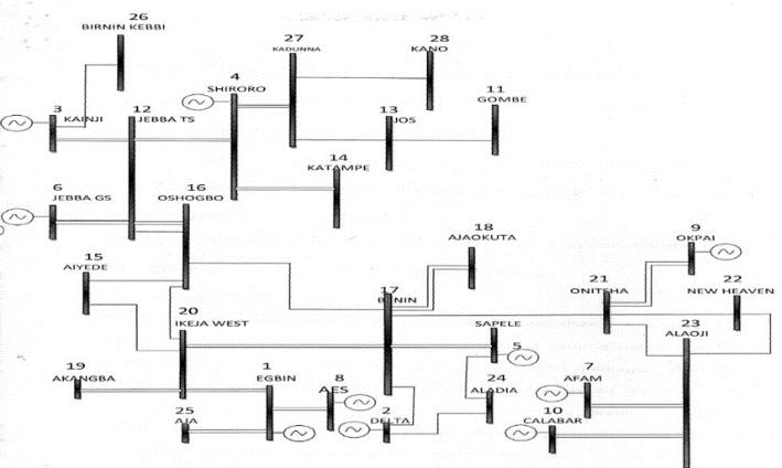
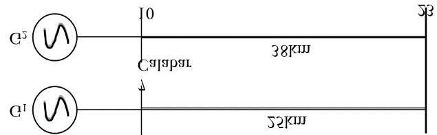
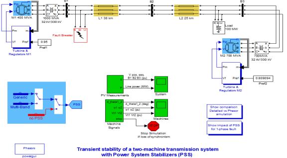
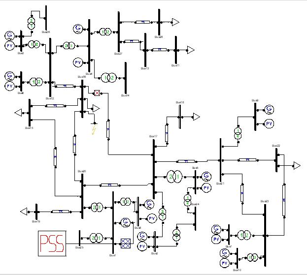
Fig.9:Angle,angularspeedandreferencevoltagefor twogenerators3 buspowernetworkwithoutpower systemstabilizer.
Table1:PSSStabilityanalysisresultforNigeria10 generators,28 buspowernetwork.
Fig.10:linepowerandVpos fortwogenerators3 bus powernetworkwithpowersystemstabilizer.
Journal | Page1517
Fig.8:linepowerandVpos fortwogenerators3 bus powernetworkwithoutpowersystemstabilizer.
schemeDesignedPSS profileVoltage point(PU)loadability/collapseMaximum loading(PU)powerTotal PSSWithout violatedbusesAll 4.5674 2.9501
Fig.11:Angle,angularspeedandreferencevoltagefor twogenerators3 buspowernetworkwithpowersystem stabilizer.
Volume:09Issue:01|Jan 2022 www.irjet.net p-ISSN: 2395-0072 2022, IRJET | Impact Factor value: 7.529 | ISO 9001:2008 Certified
International Research Journal of Engineering and Technology (IRJET) e-ISSN:2395-0056
©
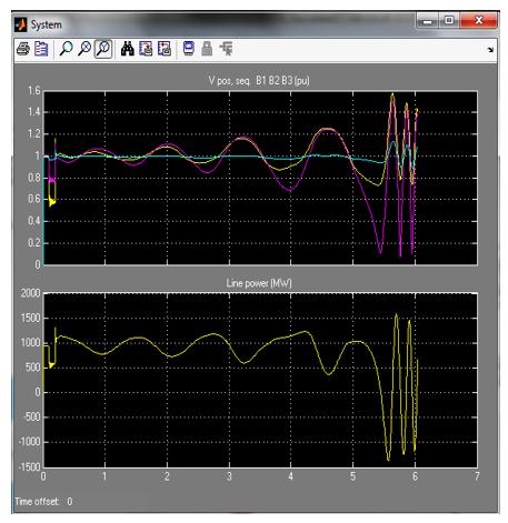
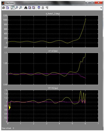
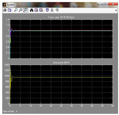
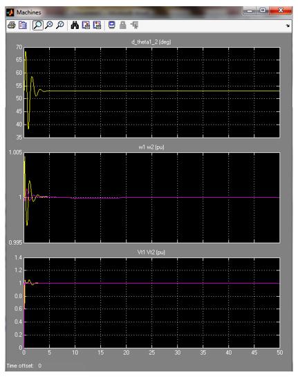
Fig.15:P Vcurvefor10generators,28 buspower networkwithPSS.
1. Anderson, P.M. and Fouad, A. A., Power System Control and Stability, 1st edition, the lowa State University Press, Ames Lowa, USA, PP.1 11, 1977.
3. Sheetekela, S., Breeder Genetic Algorithm for Power System Stabilizer Design, IEEE, 8978 1 4244 8126 2,2010.
PSSWith 14 10.1501 6.5585
Modern synchronous generators require high performance excitation systems in order to regulate the terminalvoltagequicklyandensurestableandtransient stability. Two 3 bus and 10 generators, 28 bus 330kV Nigeria power network electromagnetic damped oscillation, or swing, of the rotor instability concerns following disturbances are tackled using MATLAB/SIMULINK Power System Analysis Toolbox to create and simulate effective power system stabilizer models (PSAT). Using power system stabilizers, the 3 bus Nigeria power network with two generators and a rotorangleof4seconds,angularspeedof3seconds,and terminal voltage of 2.5 seconds all settled after 2.5 seconds. There were 14 voltage violations, 6.5585PU total power loading, and 10.1501PU maximum power factor in the 330kV Nigeria power network simulated with the power system stabilizer. Without the PSS, all buses had low and high voltage violations with total power loading points and maximum power factors of 2.9501PUand4.5674PU,respectively.
Fig.12:Voltageprofilefor10generators,28 buspower networkwithoutPSS.
Fig.13:P Vcurvefor10generators,28 buspower networkwithoutPSS.
2. Padiyar,K. R., Power System Dynamics Stability Control, 2nd edition, Indian Institute of Science, Bangalore,PP.267 268,2008.
6.CONCLUSION
International Research Journal of Engineering and Technology (IRJET) e-ISSN:2395-0056
REFERENCES
Volume:09Issue:01|Jan 2022 www.irjet.net p-ISSN: 2395-0072 © 2022, IRJET | Impact Factor value: 7.529 | ISO 9001:2008 Certified Journal | Page1518
5. Kundur, P., Klein, M., Rogers, G. J. and Zywno, M.S., Application of Power System Stabilizer for Enhancement of Overall System Stability, IEEE Transactions, Vol. PWRS 4, pp.614 626, may 1989.
6. Schleif, F. R., Hunkins, H. D., Martins, G.E. and Hattan, E. E., Excitation Control to Improve PowerLineStability,IEEEtransactions,vol.PAS 87,PP.1426 1434,1968.
7. Rogers, E.B. and Murray, E. C., Suitability of Excitation System for Power System Stabilizer Application,IEEE,0 7803 7989 6,2003.
Fig.14:Voltageprofilefor10generators,28 buspower networkwithPSS.
4. Lee, D.C. and Kundur, P., Advanced Excitation Controls for Power System Stability Enhancement, Paper 38 01, CIGRE Conference, Proc.,1986.
8. Bayne, J. P., Lee, D. C. and Watson, W. A., Power System Stabilizer for Thermal Units Based on Derivation of Accelerating Power, IEEE Transactions, Vol.96(PAS), no. 6, PP. 1777 1783,1977.
International Research Journal of Engineering and Technology (IRJET) e-ISSN:2395-0056
Certified Journal | Page1519
9. Bayne, J.P., Kundur, P. and Watson, W., Static Exciter Control to Improve Transient Stability, IEEEtransaction,vol.94(PAS),no.4,PP.1141 1146,1975.
Volume:09Issue:01|Jan 2022 www.irjet.net p-ISSN: 2395-0072 © 2022, IRJET | Impact Factor value: 7.529 | ISO 9001:2008
10. Chun Jung, C. and Tein Chi, C., Design of a Power SystemStabilizerUsinga NewRecurrent Neural Network, Proceedings of the First International Conference on Innovative Computing, Information and Control (ICICIC), 0 7695 2616 0,2006.