DEVELOPMENT
Bone regeneration represents a complicated process, of which primary biologic standards were evolutionarily conserved over a large variety of various species.Bonerepresentsoneinallfewtissueswhichcould healwithoutformingafibrousscarand,assuch,resembles acompletelyuniqueshapeoftissueregeneration.Despitea splendiddevelopmentinsurgicalstrategieswithinsidethe beyond decades, impaired bone regeneration inclusive of non unions nevertheless have an effect on a massive quantity of sufferers with fractures. As impaired bone regeneration is related to excessive socio financial implications,it'smilesancriticalscientificwanttobenefita complete know how of the pathophysiology and pick out novelremedyapproaches.
The project is mainly based on the automation of the fracture alignment process of femur bone after the fracture. It includes simple mechanical motion such as linear motion and rotational motion or twisting motion. After fractu,re the femur bone get dislocated and gets twisted too. To align the femur bone, we have to use external fixation devices. It requires constant monitoring on the patient’s movements and tedious surgeries. As per the project we are developing we are developing a mechanism which can align the femur bone on its own and the fractural gap is closed automatically. In this project we are going realign the femur bone position. After fracture the femur bone gets twisted and the twisting angle ranges from 3 33 degrees and the linear offset of the bone is 0.4 1. 5cm.The motors which are being used are stepper motors, so we can easily control the angular twist of the femur bone. And also, for the linear motion of the femur bone we are preferring stepper motor for the required linear motion with reference of time.
Femurboneisalsoknownasthighbone.Thefemurboneis thelongest,heaviestandstrongestboneinthehumanbody. Thelengthofthisboneisalmost26%oftheheightofperson. Femur bone is divided into three parts: upper extremity, bodyandlowerextremity.Theupperpartconsistsofhead, neckandthetowtrochanters.Bodyisthelongandalmost cylindricalinshape.Itisslightlyarched.Lowerextremityis biggerthanupperextremity.Itisslightlycuboidinformbut itsdiagonaldiameterisbiggerthanitsanteroposterior. 1 2. StepMETHODOLOGY1: Westartedtheworkofthisprojectwithaliterature survey. We gathered many research papers which are relevanttothistopic.Aftergoingthroughthesepapers,we learntaboutbonerupturetreatment.
Fig
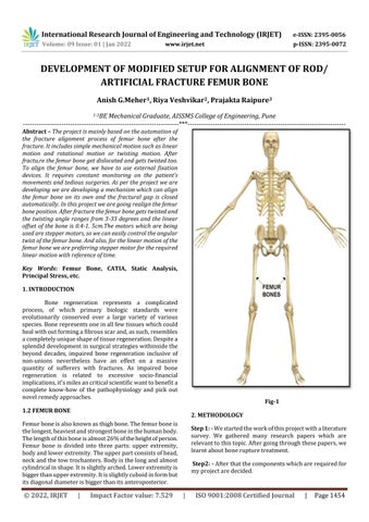
1.2 FEMUR BONE
International Research Journal of Engineering and Technology (IRJET) e ISSN: 2395 0056 Volume: 09 Issue: 01 | Jan 2022 www.irjet.net p ISSN: 2395 0072 © 2022, IRJET | Impact Factor value: 7.529 | ISO 9001:2008 Certified Journal | Page1454
Key Words: Femur Bone, CATIA, Static Analysis, Principal Stress, etc.
OF MODIFIED SETUP FOR ALIGNMENT OF ROD/ ARTIFICIAL FRACTURE FEMUR BONE
Anish G.Meher1 , Riya Veshvikar2, Prajakta Raipure3
1 3BE Mechanical Graduate, AISSMS College of Engineering, Pune ***
Abstract
1. INTRODUCTION
Step2: Afterthatthecomponentswhicharerequiredfor myprojectaredecided.

International Research Journal of Engineering and Technology (IRJET) e ISSN: 2395 0056 Volume: 09 Issue: 01 | Jan 2022 www.irjet.net p ISSN: 2395 0072 © 2022, IRJET | Impact Factor value: 7.529 | ISO 9001:2008 Certified Journal | Page1455
Bone: I.
V.
Step
Step 5: - ThestaticanalysisonANSYSwillbecarriedoutand thentheresultandconclusionwillbedrawn.
IV.
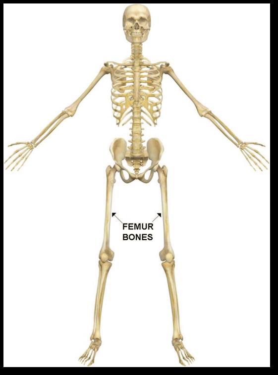
Fig 2 3.2 Femur Bone samples:Fig 1
II.
III.
Step 3: Afterdecidingthecomponents,the3DModeland draftingwillbedonewiththehelpofCATIAsoftware. 4: The components will be manufactured and then assembledtogether.
DATA 3.1MethodCOLLECTIONtofindAngular and
3. Linear Offset for broken MarkpointsonthefracturedBoneX rayP1toP10. Drawparallellinescoincidingwiththesepoints. DrawthecenterlineofbothpartsoftheBone. Theintersectionpointwherebothcenterlinesmeet, markthatpoint. MeasuretheanglenowandthuswegettheAngular Offset.
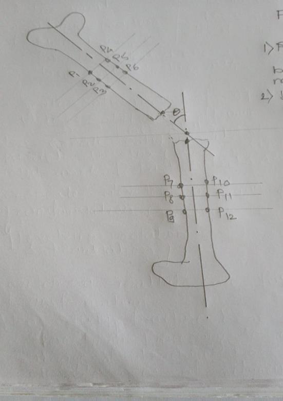
International Research Journal of Engineering and Technology (IRJET) e ISSN: 2395 0056 Volume: 09 Issue: 01 | Jan 2022 www.irjet.net p ISSN: 2395 0072 © 2022, IRJET | Impact Factor value: 7.529 | ISO 9001:2008 Certified Journal | Page1456 Angular Offset is 30 Fig 2 Angular Offset is 1)lateral-12.50 2)A.P 30
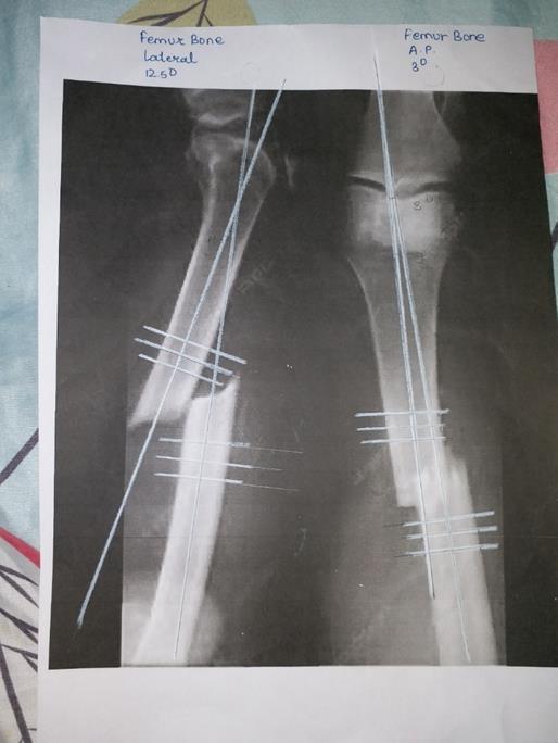
International Research Journal of Engineering and Technology (IRJET) e ISSN: 2395 0056 Volume: 09 Issue: 01 | Jan 2022 www.irjet.net p ISSN: 2395 0072 © 2022, IRJET | Impact Factor value: 7.529 | ISO 9001:2008 Certified Journal | Page1457 3.3Table for Bone Offsets X RAY NO. Bone Type Angular Offset Linear Offset View 1. Femur 14° Lateral 2. Femur 9° AnteroPosterior 3. Femur 18° Oblique 4. Femur 10° AnteroPosterior 5. Femur 9° AnteroPosterior 6. Femur 4° Lateral 7. Femur 12.5° Lateral 8. Femur 12.5° Lateral 9. Femur 3° AnteroPosterior 10. Femur 21° Lateral 11. Femur 7° AnteroPosterior 12. Femur 17° AnteroPosterior 13. Femur 15° Lateral 14. Femur 6° AnteroPosterior 15. Femur 33° AnteroPosterior
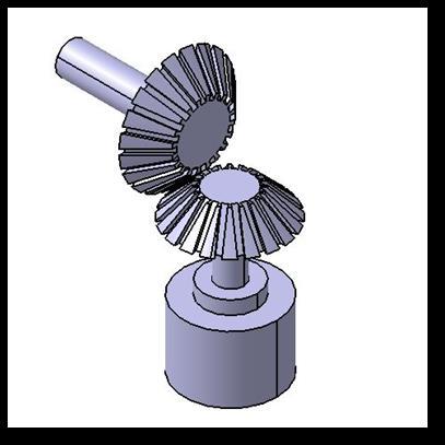
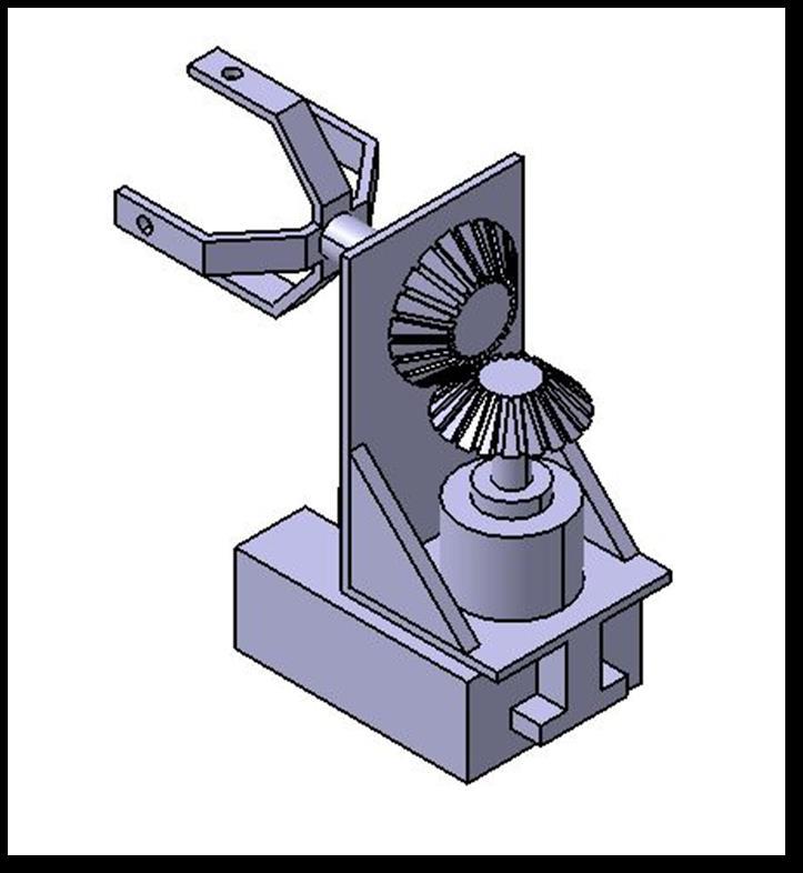
4.2Orthographic and Isometric view of the model: Fig 3 Fig 4 4.3. Components : 1) Bevel gears: Fig-5
4.1CATIA CATIA is a leading product design platform created by a companywithheadquartersinFrance.Itisagreattoolfor companiestocomeupwithdesigns,performcomprehensive analysis,and produce new products thatcan behelpful in product development. CATIA can benefit OEMs and manufacturersinvariousindustriesastheycanusethetool to ensure faster analysis, design and creation of new products. This revolutionary software integrates different approaches to product design and development, allowing different industries to use their current tools at different stagesofproductdevelopment.,makingCATIAconvenient for architects, engineers and industrial designers. CATIA provides an efficient 3D design environment that allows stakeholders and designers to work together on product prototyping and to share their product designs.
International Research Journal of Engineering and Technology (IRJET) e ISSN: 2395 0056 Volume: 09 Issue: 01 | Jan 2022 www.irjet.net p ISSN: 2395 0072 © 2022, IRJET | Impact Factor value: 7.529 | ISO 9001:2008 Certified Journal | Page1458
4. Design consideration and calculations
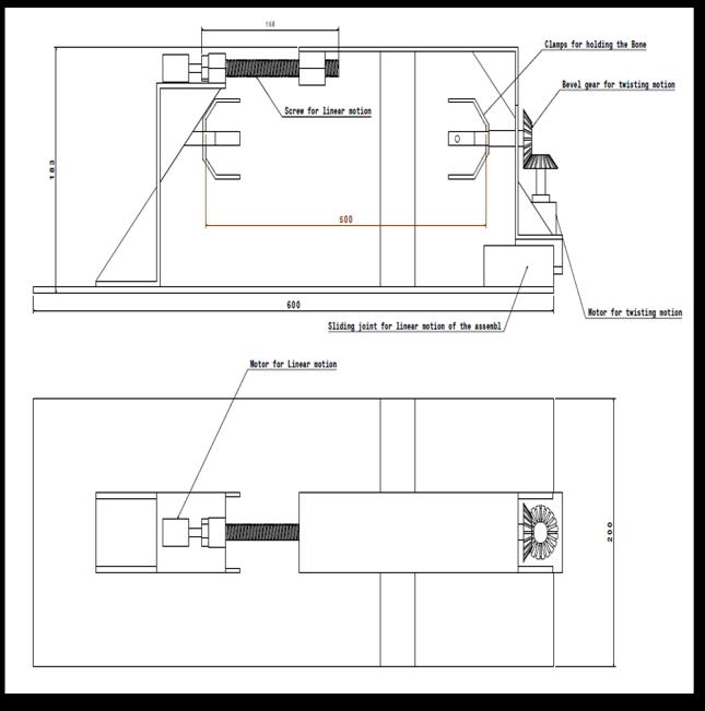
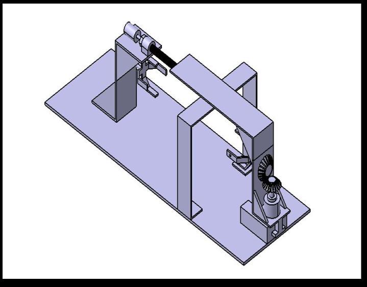
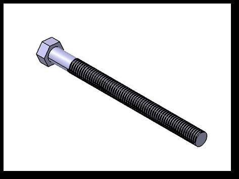
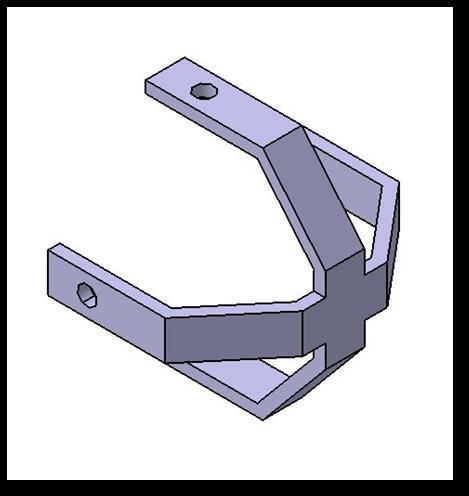
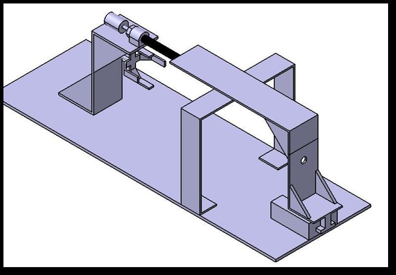
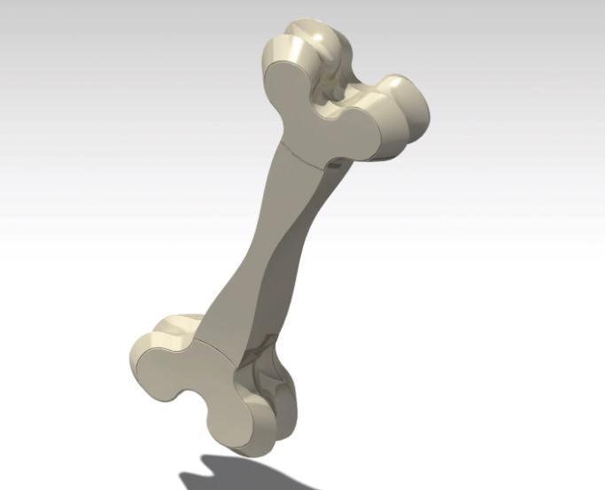
International Research Journal of Engineering and Technology (IRJET) e ISSN: 2395 0056 Volume: 09 Issue: 01 | Jan 2022 www.irjet.net p ISSN: 2395 0072 © 2022, IRJET | Impact Factor value: 7.529 | ISO 9001:2008 Certified Journal | Page1459 2) Bolt for linear motion:Fig 6 3)Clamp for holding bone:Fig 7 4) Setup for Linear motion:Fig-8 5)Setup for twisting motion:Fig 9 6) Artificial 3D bone: Fig 10
International Research Journal of Engineering and Technology (IRJET) e ISSN: 2395 0056 Volume: 09 Issue: 01 | Jan 2022 www.irjet.net p ISSN: 2395 0072 © 2022, IRJET | Impact Factor value: 7.529 | ISO 9001:2008
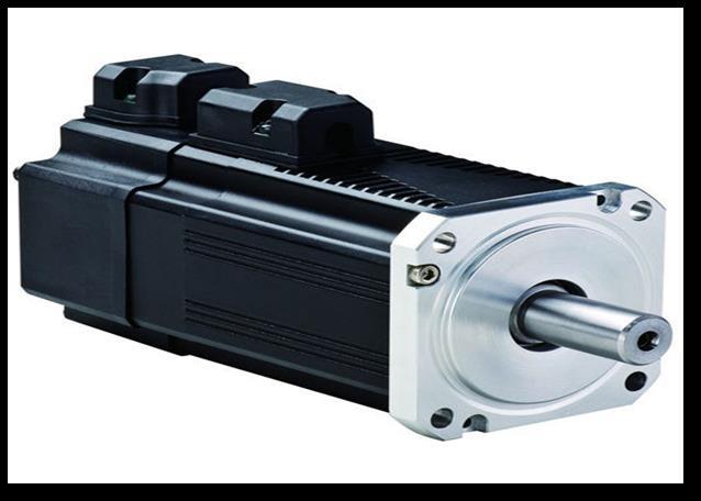
Servomotorsarenotaspecificclassofmotoralthoughthe term servomotor isoftenusedtorefertoamotorsuitablefor useinaclosed loopcontrolsystem. Servomotorsareusedinapplicationssuchasrobotics,CNC machineryorautomatedmanufacturing.
We have assumed that the bolt we are using for linear motionofthebonewouldbeM12andthegearswhichwe haveusedinthemechanismareselectedasperavailability inthemarket. Thetwistingmomentandthelinearmotionoftheboneare controlledbythemotors,whicharebeingprogrammedas per Therequirement.motorthat we are using for the motion is being calculatedasfollows: Base motor design Let,P=24watt,12volt,&2A Power(P)=2πNT/60 T=24*60/2π10 T =22.91Nm thisistheavailabletorque Consider the weight of the male femur bone = 290 grams
Fig 11 Servometer 6. Analysis :
Thefiniteelementmethod(FEM)isanumericalmethodfor solvingproblemsinengineeringandmathematicalphysics. Typicalproblemareasofinterestincludestructuralanalysis, heattransfer,fluidflow,masstransport,andelectromagnetic potential. Analytical solutions of these problems often require the solutions of limit value problems for partial differential equations. The construction of the problem accordingtothefiniteelementmethodleadstoasystemof algebraic equations. This method provides approximate valuesoftheunknownsinadiscretenumberofpointsinthe field.Tosolvetheproblem,hedividedalargeprobleminto smaller, simpler parts called finite elements. The simple equations that model these finite elements are then assembledintoalargersystemofequationsthatmodelthe whole problem. FEM then uses variable computation methods to approximate a solution by minimizing an associated error function. Studying or analyzing a phenomenonwithFEMisoftenreferredtoasFiniteElement Analysis(FEA).
4.4 Basic ASSUMPTIONScalculations:
Certified Journal | Page1460
So(approximately)theforceappliedisequalto=0.290x9.81newton. F= 2.845 N Astheweightoftheboneisappliedonthebevelgearand thebevelgearisattachedtothemotor.So,wecancalculate thetorquerequiredformotortorotatetheboneHence,the torquerequired=2.845x20mm =56.9N mm= 0.0569 N m So we have to select a motor having considerably similar torqueascalculated.
5. SERVO MOTOR: A servomotor is arotary actuatororlinear actuatorthat allows for precise control of angular or linear position, velocity and acceleration.It consists of a suitable motor coupledtoasensorforpositionfeedback.Italsorequiresa relativelysophisticatedcontroller,oftenadedicatedmodule designedspecificallyforusewithservomotors.
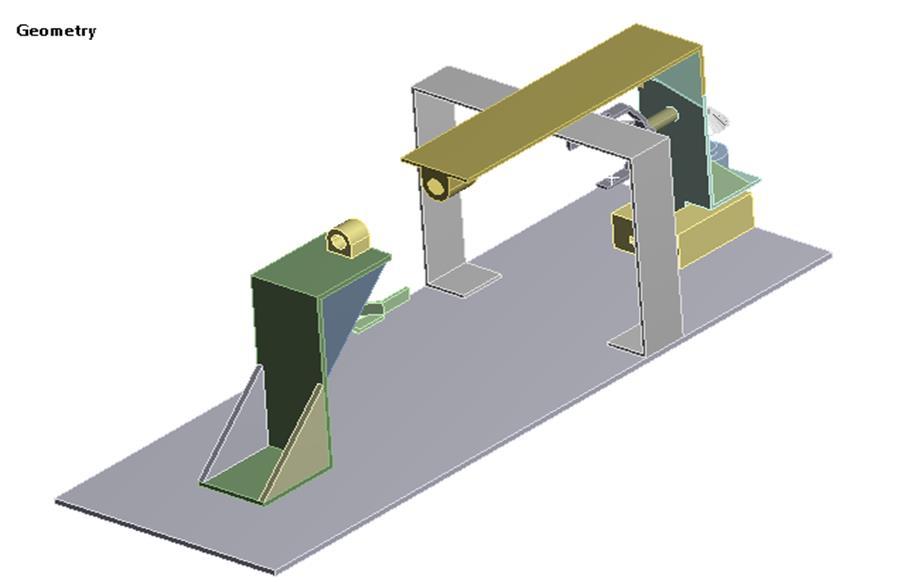
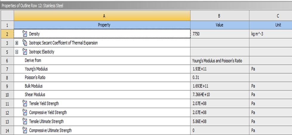
International Research Journal of Engineering and Technology (IRJET) e ISSN: 2395 0056 Volume: 09 Issue: 01 | Jan 2022 www.irjet.net p ISSN: 2395 0072 © 2022, IRJET | Impact Factor value: 7.529 | ISO 9001:2008 Certified Journal | Page1461 6.1 Geometry: Fig 12 Material used: Fig 13
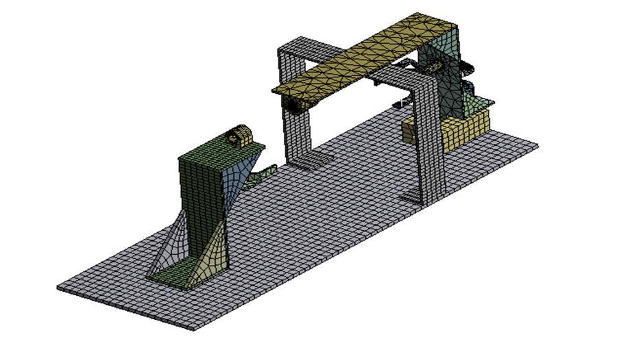
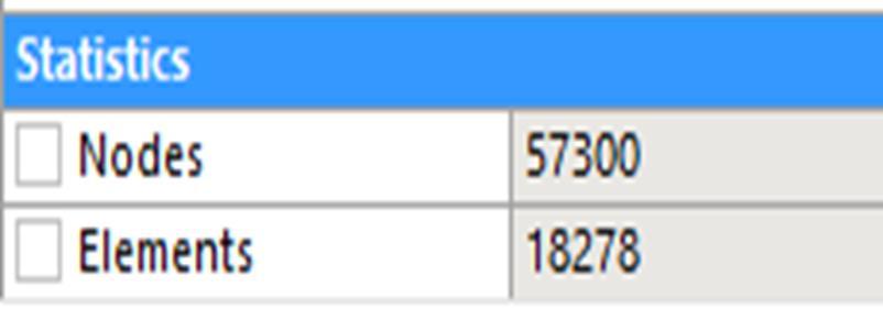
International Research Journal of Engineering and Technology (IRJET) e ISSN: 2395 0056 Volume: 09 Issue: 01 | Jan 2022 www.irjet.net p ISSN: 2395 0072 © 2022, IRJET | Impact Factor value: 7.529 | ISO 9001:2008 Certified Journal | Page1462 6.2 Meshing: Fig 14 NODES AND ELEMENTS: Fig-15
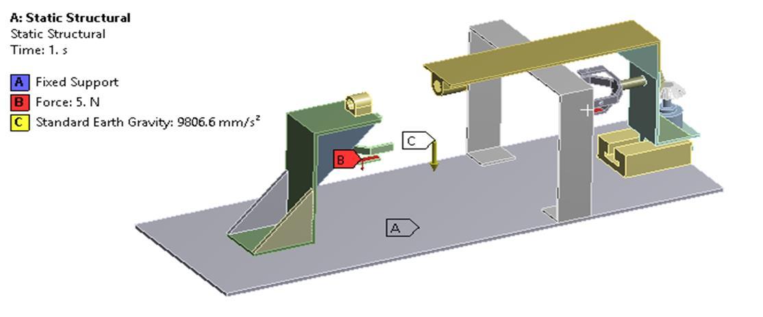
International Research Journal of Engineering and Technology (IRJET) e ISSN: 2395 0056 Volume: 09 Issue: 01 | Jan 2022 www.irjet.net p ISSN: 2395 0072 © 2022, IRJET | Impact Factor value: 7.529 | ISO 9001:2008 Certified Journal | Page1463 6.3 STATIC ANALYSIS OF FRAME BOUNDARY CONDITION:Fig 16 Astheboneisbeingclampedontheclampswhichhasweightof500gramthan5Nofforceisappliedontheclampandalsothe standardgravitationalforcewillalsoactontheframe. 6.4 RESULTS AND PLOT OF THE ANALYSIS: Fig-17
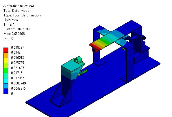
we
The
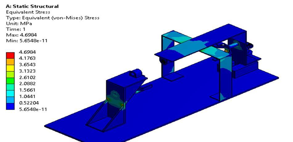
MAXIMUM wehavedonestaticstructuralanalysisoftheframe, haveplottedtheresultsoftotaldeformationordefectionofthe chassis. stressesthatarebeingdevelopedinsidethechassisandalsothemaximumprinciplestress inducedinsidechassis. theyieldstrengthofthematerialisgreaterthanthestressesdevelopedinsidechassis.Sothedesignissafe.
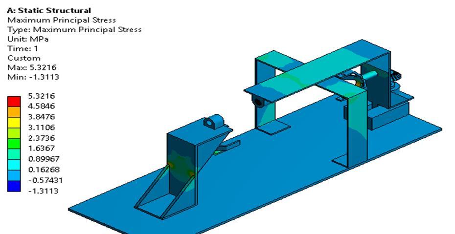
International Research Journal of Engineering and Technology (IRJET) e ISSN: 2395 0056 Volume: 09 Issue: 01 | Jan 2022 www.irjet.net p ISSN: 2395 0072 © 2022, IRJET | Impact Factor value: 7.529 | ISO 9001:2008 Certified Journal | Page1464 TOTAL DEFORMATION IS 0.0386MM 6.5 EQUIVALENT STRESS PLOT OF FRAME: Fig-18 EQUIVALENT STRESS IS OBSERVED TO BE 4.6984 MPa 6.6 MAXIMUM PRINCIPLE STRESS PLOT: Fig 19
As
PRINCIPLE STRESS IS 5.32 MPa As
8. ACKNOWLEDGEMENT
8. AmanSharma,HarishGarg ;“Utility and challenges of 3 D Printing”
REFERENCES
9. Masaaki TSUTSUBUCHI, Tomoo HIROTA, Yasuhito NIWA, Tai SHIMASAKI;“Application of Plastics CAE:Focusing on Impact Analysis”
3. R.D.Burghardt,D.Paley,S.C.Specht,J.E.Herzenberg; “The effect on mechanical axis deviation of femoral lengthening with an intramedullary telescopic nail”
10. ZhenChen;“Research on the Impactof3DPrintingon the International Supply Chain”
1. The significant targets and related work plan can be extensivelycompressedas: i.Tostudytheworkingprinciple,componentsanddetailsof theequipment.
ii.Tocreateasolidmodelofthebasicstructurewhichaligns thebones.
11. Michael Dawoud, Iman Taha, Samy J. Ebeid; “Strain sensing behavior of 3D printed carbon black filled ABS”
Raipure Graduate
AnishG. AISSMSMechanicalGraduateRiyaAISSMSMechanicalGraduateMeherStudent,Engineering,COE,Pune.VeshvikarStudent,Engineering,COE,Pune.
Prajakta AISSMSMechanicalStudent,Engineering,COE,Pune
3. Significantly reduces pain through which the patient is sufferingduringtreatmentperiod.
Thesatisfactionthataccompaniesthesuccessfulcompletion ofthispaperwouldbeincompletewithoutthementionof thepeoplewhomadeitpossible.Weconveyourregardsto ourguideProf.PankajAglaweoftheMechanicalEngineering Departmentwhohelpedusateachandeverystepinevery possibleway.
1’st 2nd Author Photo
2. M. Olliver, S. Parratte*, L.Lecoz, X. Flecher, J. N. Argenson;“Relation between lower extremity alignment and proximal femur anatomy. Parameters during total hip arthroplasty.”
7. Tiantian Li , Lifeng Wang; “Bending behavior of sandwich composite structures with tunable 3D printed core materials”
5. LifengWang,JackyLau,EdwinL.Thomas,andMaryC. Boyce ;“Co Continuous Composite Materials for Stiffness, Strength, and Energy Dissipation”
6. AubreyL.Woern,JosephR.McCaslin,AdamM.Pringle, Joshua M. Pearce; “Reparable Recycle bot: Open source 3 D printable extruder for converting plastic to 3 D printing filament”
BIOGRAPHIES
4.Treatmentwillbedoneinveryminimalcost
International Research Journal of Engineering and Technology (IRJET) e ISSN: 2395 0056 Volume: 09 Issue: 01 | Jan 2022 www.irjet.net p ISSN: 2395 0072 © 2022, IRJET | Impact Factor value: 7.529 | ISO 9001:2008 Certified Journal | Page1465
7. CONCLUSIONS:
2.It reduces (halves or more) treatment time required for completehealingandalignmentofbone.
1. Vincent V.G., Joshua Twiggs, Murilo Leie, Brett A . Fritsch; “Kinematic alignment is bone and softtissue preserving compared to mechanical alignment in total knee arthroplasty.”
4. Scott E. Sheehan, Jeffrey Y. Shyu, Michael J. Weaver, AaronD.Sodickan,BhartiKhurana;“Proximal Femoral Fractures: What the Orthopedic Surgeon Wants to Know”