Analysis, Design, and Estimation of Multi-Storied Institutional Building by using ETABS Ananda G1 , Dr.M.S. Shobha2
The design for beams, columns, and footing is derived from ETABS, which with its additional feature, outperformed its predecessors in teams of data exchange.
Our project’s major goal is to learn about many design components such as modelling, analysis, and design. We intendtoconstructamulti storybuildingwithaG+3floor. ETABSsoftwareisthemostpopulardesignprograminthe markettoday.Thisprogramisusedbyalotofdesignfirms for project design. As a result, the major focus of this article is on a comparison of the findings produced from manual and ETABS software analyses of a multi story buildingstructure
2. OBJECTIVES
•Creating structural frame like column, slab, staircase, modelbyusingETABS 2018.
•CalculatetheEstimationandCostofthestructure.
The finding of the analysis has been used to confirm the structure’s suitability for usage. For a complicated structural system, computer software is also utilized to calculate forces, bending moment, stress, strain, and deformation or deflection. The main goal of this project is to compared ETABS design and analysis of a multi story structure
Our major goal is to finish a multi story building and verify that it’s safe and cost effective under gravity loading circumstances while still performing the purpose for which it was designed. The dead and live are taken into account while designing the structure. The structure was analyzed and designed using the ETABS software tool. We used the limit state approach of analysis in this assignment. The design meets the requirement IS 456 2000
•Design and Analysis of structure by using ETABS 2018 software. •DesignofstructuremanuallyasperIScodesprovision.
2Professor, Department of Civil Engineering RYM Engineering College, Ballari, Karnataka, India ***
Abstract
Key Words: dead load, live load, ETABS, multi storeyed building, 1. INTRODUCTION
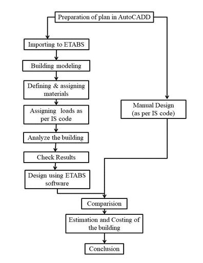
3. METHODOLOGYFig1 :Methodologyoftheproject
International Research Journal of Engineering and Technology (IRJET) e ISSN: 2395 0056 Volume: 09 Issue: 01 | Jan 2022 www.irjet.net p ISSN: 2395 0072 © 2022, IRJET | Impact Factor value: 7.529 | ISO 9001:2008 Certified Journal | Page1346
ETABS V.16.0.0 allows for any building layout, however, in most circumstances, a simple grid system characterized by horizontal floors and vertical column lines may generate building geometry with minimal effort. The building has a lot of comparable floor levels. This resemblance may be utilized to speed up modeling and design.
AutoCAD
1PG Student, Department of Civil Engineering RYM Engineering College Ballari, Karnataka, India
The majority of the structure has a simple geometry with horizontal beams and vertical columns.
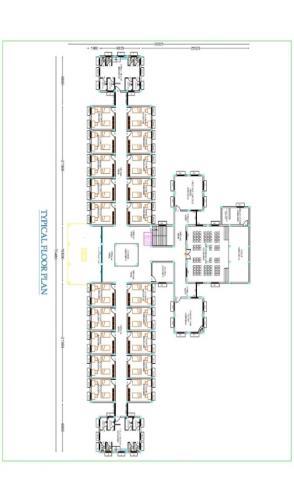
•Generatingstructuralframeofthegroundplan,floorplan, andcolumnpositiondrawing ofthePGbuildingbyusing

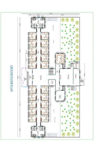
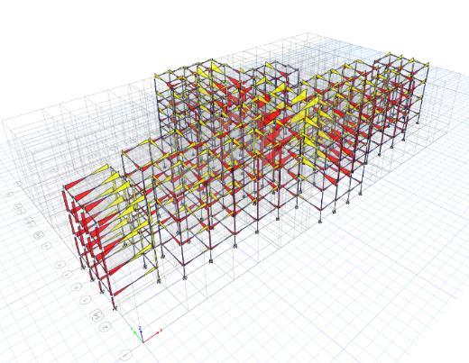
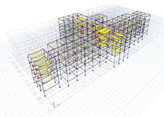
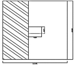
International Research Journal of Engineering and Technology (IRJET) e ISSN: 2395 0056 Volume: 09 Issue: 01 | Jan 2022 www.irjet.net p ISSN: 2395 0072 © 2022, IRJET | Impact Factor value: 7.529 | ISO 9001:2008 Certified Journal | Page1347 4. PLAN OF THE BUILDING Fig 2: Groundfloorplan;typicalfloorplan 5. ANALYSIS RESULTSFig3 :3 Dshearforcediagram Fig 4:3 DBendingmomentdiagram 6 DESIGN DETAILS 6.1. Slab design Lx =4.23m Ly =5.23m Ly/Lx =1.24<2 Becausethelongtoshortspanratiois lessthan 2, should bedesignedasatwo wayslab. Assumeslabthickness=150mm Cover =25mm
SHORT SPAN MOMENT: Atcontinuousedge: Mux =αxWulx2 =0.062X13.125X4.232 =14.56KN m Atmidspan: Mux =αxWulx2 =0.0466X13.125X4.232 =10.93KN m LONG SPAN MOMENT: Atcontinuousedge: Muy =αyWulx2 =0.062X13.125X5.232 =22.25KN m Atmidspan: Muy =αyWulx2 =0.0466X13.125X3.352 =17.50KN m CHECK FOR DEPTH: Forbalanced(Mulim )section, Mulim =0.138fck*b*d2 B =1000mm
LOAD CALCULATION: Deadload = 0.151 X 251 =3.751KN/m2 serviceload =3KN/m2 Floorfinish =1KN/m2 Partitionwall =1KN/m2 Totalload =8.75KN/m2 FactoredloadWu =1.5x =13.128.755KN/m2
ULTIMATE DESIGN MOMENT: supportcondition: Twoadjacentedgesdiscontinuous. Fromtable26ofIS456:2000bendingmomentcoefficients forlongtoshortspanratiois Coefficients Continuous edge Midspan αx 0.062 0.0466 αy 0.047 0.035
Journal | Page1348
International Research Journal of Engineering and Technology (IRJET) e ISSN: 2395 0056
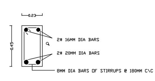
Fig -4:Reinforcementdetailsalongalongspan Fig -5:Reinforcementdetailsalongtheshorterspan 6.2. Beam Dimensionofbeam =230×450mm Maxsupportmoment =95kN m Middelspanmoment =45kN m Mulim =0.138fckbd2 =0.138×200×230×4252 =114.660kN m AT SUPPORT SECTION: Mu =95kN m <Mulim Hencedesignsinglyreinforcedbeam Mu/bD2 =(95X106/30x4506)=2.03
22.25X106 =0.138X20XbXd2 D =80.78mm<150mm Henceslabissafeindepth.
Pt =0.655 Tensilesteel;Ast =Pt(bd)/100=(0.655x230x425)/100 Ast =640.26mm2 provide16mmϕbar No.ofbars = Ast/ast = 640.26/314.16 ≈ 2 bars Provide2bars16mmϕ
Fromfig.4ofIS456:2000,for Pt=0.144;kt=1.7 (L/d)max =20X1.7=34mm (L/d) actual =423/125=33.84mm For Pt =0.144 (L/d) actual< (L/d) max Thereforslabissafeindeflection
Vu =0.5Wu Lx =0.5X13.125X4.23=27.76KN τv = V_u/(bd) =(27.76x10^3)/(1000x125) =0.222N/mm2 Pt =(100Ast)/(bd)=(100X 180)/(1000X 125)=0.144
Ast =431.43mm2 Astmin =0.12%ofthecross sectionalarea =0.0012X1000X150=180mm2 Use8mmϕbar Spacing =a_st/A_st x1000 =50.26/431.43x1000 =115.25mm Hence 8mmϕbar@110mmc/c Atmidspan: Mux =17.50KN m Mu =0.87fyA_std[1 (Ast Xfy)/(bdfck )] Ast =335.59mm2
Midspan: Muy =10.93KN m Mu =0.87fyA_std[1 (AstXfy)/(bdfck )] Ast =198.80mm2 Use8mmϕbar Spacing=50.26/198.80x1000=252.81mm Provided8mmϕbar@250mmc/c
CHECK FOR DEFLECTION: Considering the unit width of the slab in the short span directionLx (L/d) basic =20
Fromtable2ofSP16codebook
Using8mmϕbar Spacing =50.265/335.59x1000=149.76mm Hence8mmϕbar@140mmc/c
Volume: 09 Issue: 01 | Jan 2022 www.irjet.net p ISSN: 2395 0072 © 2022, IRJET | Impact Factor value: 7.529 | ISO 9001:2008 Certified
STEEL REINFORCEMENT: LONG SPAN: Atcontinuousedge: Mux =22.25KN m Mu =0.87fyAst *d[1 (AstXf_y)/(bdf_ck) 14.46X10⁶ ¬= 0.87X415XAstX150[1 (AstX415)/(1000 x150x25) ]
From table 19 of IS 456:2000, for M20 concrete and Pt = 0.144 τc = 0.28N/mm2> τv slabissafeinshearstress.
Using8mmϕbar Spacing = 50.26/227.35x1000 =221.06mm Provide8mmϕbar@220mmc/c
SHORTER SPAN: Continuesedges: Mu =14.56KN m Mu =0.87fyA_std[1 (Ast Xfy)/(bdfck )] Ast =227.35mm2
CHECK SHEAR STRESS: Consideringtheshortspanandunitwidthofslab
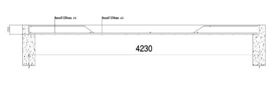
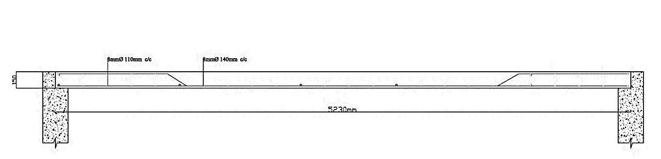
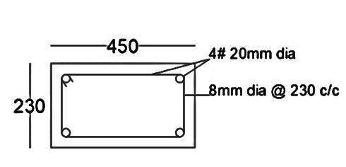
Fig 6:ReinforcementdetailsofBeam 6.3. Column Pu =600kN Mu =12.15kN m Unsupportedlength =3m Clear cover =40mm fck =20kN/m2 Column are the held in position and restrained against Lrotation. eff=0.65L =0.650x3= 1.950m Columndimension =230x450mm Leff/D =1.95/0.45=4.3<12 Leff/b =1.95/0.23=8.5<12 therefore,columnaredesignshortcolumn CHECK FOR ECCENTRICITY: emin =l/500+D/30 =3000/500+450/30 =21 emin/D =21/450 =0.044<0.05
International Research Journal of Engineering and Technology (IRJET) e ISSN: 2395 0056
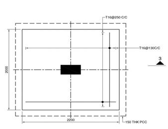
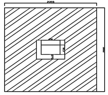
Fig 7:ReinforcementdetailsofColumn 66.4. Footing UltimateloadPu =1150KN Live loadP =767KN deadweightoffooting =10%oflive load =76.7KN overallload =843.7KN AssumeSBC =195KN/m2 Areaoffootingrequired=8371/1951=4.29m2 Providefootingofdimension=2X2.2m SOILPRESSUREFORDESIGN: qu =1150/(2X2.2) =261.36KN/m2 =0.261N/mm2
AT MID SECTION: Mu =45kN m<Mulim Hencedesign singlyreinforcedbeam Mu/bD^2 =(45×10)^6/(230×450^2)=0.966 Fromtable2ofSP16 Pt =0.28 Areaoftensilesteel Ast =Pt (bd)/100 =(0.28x230x425)/100 Ast =273.7mm2 Provide12mmϕbar No.ofbars =Ast/ast =273.7/201.06≈2bars Provide2barsof16ϕ. SHEAR REINFORCEMET: Vu =90KN b =230mm d=425mm Nominalshearstress Τv =Vu/bd =(90×1000)/(230×425) =0.869N/mm2 Pt =(100Ast)/(bd)=0.600 Fromtable19ofIS456:2000 τc =0.512N/mm2<τv therefore,providesharereinforcement provide2leged8mmϕverticalstirrups Asv =20×π/40×802=100.530mm2 Vus =Vu τc bd=(0.87 fyAsvd)/Sv 90× 103 0.512 × 230 ×425 = (0.87 × 415×100.53×425)/Sv SpacingSv =195mm Provide2Legged8mmϕverticalstirrups@190c/c.
Designshortcolumn. Designoflongitudinalreinforcement: Mu/fckbD^2 = (12.15x 10^6)/(20 x 230x450^2) =0.013 Pu/(fckbD) = 600 x 10^3/(20 x 230 x450)=d^'/D0.298 =40/450 =0.088≈0.013, SP:16(chartbook)codebook Pt/(fck ) =0.04 p=0.04x20 =0.8% ∴ Asc =0.8/100 bD =0.8/100 x230x450 Asc =828mm2 Provide4no 20mmϕsteel.
LATERAL REINFORCEMENT: diameterofthelateraltiesismustnotbelessthan ∅⁄4=8mm (b)5mm Provide8mmϕbars Minimumspacingprovidedtobe smallerlateraldimension=230mm 16x∅ =400mm 300mm Hence8mmdiameteroflateraltiesat230mc/c
Volume: 09 Issue: 01 | Jan 2022 www.irjet.net p ISSN: 2395 0072 © 2022, IRJET | Impact Factor value: 7.529 | ISO 9001:2008 Certified Journal | Page1349
_st =117.200mm2 Ast min =0.12%crosssectionalarea =0.0012*3000*6500=2340mm2 A_st<Astmin henceprovideAstmin Use16 barSpacing=(π⁄4 x16^2)/2340X1500≈130mm Provide16 bars@1300mmc/c Inshortdirection: Mu =155.45x10⁶ Mu =0.87xfy xAst xdx[1 (Astxfy)/(fckxb x Md)] u = 0.87 x 415 x Ast x 600 x [1 (Ast x 415)/(20x2000 x600)] Ast =117.25mm2 Astmin =0.12%*crosssectionalarea =0.0012X1500X650=1170mm2 Ast<Astmin henceprovideAstmin Use16diameterbar Spacing=(π⁄4 x16^2)/1170X1500≈250mm Provide 16diameterbar@250mmc/c
Nominalshear(τv) = Vu/(resisting area) = (160x 10^3)/(1.368x10^6) =00.117N/mm2 Butpermissibleshearstress=ks*τc ks=(0.50+β)<01 β1 =b/d = 230/600=0.4 ks=0.960 Take ks =1 τc=0.250√(fck)= 0.25x√200=1.110N/mm2 Permissibleshearstress=1.11N/mm2 >τv footingaresafeintwowayshear.
Punchingshearforce =38.28[3.00*1.5 0.68*0.46 =160KN
Page
DESIGN OF REINFORCEMENT: Inlongdirection: Mu =155.45x10⁶ Mu =0.87X fy XAst Xd X[1 (Ast Xfy)/(fckXbX d)]38.28X106=0.87X415xAstX600X[1(Astx415)/(20X2200X A600)]
ONE WAY SHEAR: LetsAssumept =0.15,τcforM20 concrete=0.32N/mm2 Vu =τcb 0.261d*1500(1275 d) =0.320 *1500*d d= Take572.76mmd=600mm D=650mm CHECK FORFigDEPTH:8 :Cross sectionforonewayshear Mu =qu X2000X (775^2)/8 Mu =0.255X2000X 775^2/8 Mu =38.28KN m Mulim =0.138fck bd^2 =0.138 X20X2000X600^2 =1987.2KN mlessthan Mu safeindepth
International Research Journal of Engineering and Technology (IRJET) e ISSN: 2395 0056 Volume: 09 Issue: 01 | Jan 2022 www.irjet.net p ISSN: 2395 0072 © 2022, IRJET | Impact Factor value: 7.529 | ISO 9001:2008 Certified Journal | 1350
Checkfortwo wayshare: Fig 9:Cross sectionfortwo wayshear Perimeterofresistingsection b1 =20*(680+460) =2280mm Resistingarea =perimeterxd =2280x600 =1.368x106mm2
International Research Journal of Engineering and Technology (IRJET) e ISSN: 2395 0056 Volume: 09 Issue: 01 | Jan 2022 www.irjet.net p ISSN: 2395 0072
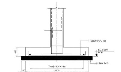
Fig 10:ReinforcementdetailsofrectangleFooting
•Wemayestimatethecostoftheentirestructurebasedon the “analysis and design “ before the construction begins.
ACKNOWLEDGEMENT Specialthanksto“Swathiinfostructures”andourguideDr. M.S.Shobha
Asaresult,the wholeexpenditureof thestructurewill be knownaheadoftime.
REFERENCES
•These structural components are tested to ensure that theymeettheserviceabilitystandards,andthedimensions ofallstructuralcomponentsaresufficient.
[1] Divya Bahraini HOD Nova College of Engineering and Technology:“OptimizedDesignofaG+20StoriedBuilding Using ETABS”. There is a gradual increase in the value of lateral forces from the bottom floor to top floor in softwareanalysisIJMET,vol 3Oct.2016(1520 1529)
© 2022, IRJET | Impact Factor value: 7.529 | ISO 9001:2008 Certified Journal | 1351
7. Conclusion •Thisprojectstudyattendedtoprovideinformationofthe component of a multi story structural drawing are reviewed,aconceptofstructuralpartsmaybeobtained.
•For all loading combinations, ETABS used employed for the analysis since it minimizes time and provides the neededaccuracy.
[2] Rohit Kumar. : Analysis and design of Multistory Structure Using ETABS (IRJET).” The analysis and design results obtained from software are safe when compared with manual calculations and design”. IRJET May 2017 3504 3509 [3]V.Varalakshmi:“Thedesignandanalysisofmultistore G+4 building at kukatpally”, Hyderabad, India. IRJET June 2016887 891. [4] IS 456 2000, Code of Practice Plain and Reinforced [5]concrete.IS875 1987 (Part 1) 1987, Code of Practice for Design Loads (other than earthquake) for buildings and [6]structures.IS875 1987 (Part 2) 1987, Code of Practice for Design Loads (other than earthquake) for buildings and structures Imposedloads. [7] IS SP 16:1980, code design aids for reinforced concrete. BIOGRAPHIES AnandaG P.G. DepartmentScholarofCivilEngineering., RYMENGINEERINGCOLLEGE BALLARI,Karnataka,India. Dr.M.S. DepartmentProfessor.ShobhaofCivilEngineering., RYMENGINEERINGCOLLEGE BALLARI,Karnataka,India.
Page