International Research Journal of Engineering and Technology (IRJET) e-ISSN: 2395-0056
Volume: 09 Issue: 12 | Dec 2022 www.irjet.net p-ISSN: 2395-0072
International Research Journal of Engineering and Technology (IRJET) e-ISSN: 2395-0056
Volume: 09 Issue: 12 | Dec 2022 www.irjet.net p-ISSN: 2395-0072
1Cumhuriyet University, Department of Energy Science and Technology Engineering, Sivas, Türkiye 2Cumhuriyet University, Renewable Energy Research Center (CUYEM), Sivas, Türkiye 3 Cumhuriyet University, Coordination of Sustainability Office, Sivas, Turkey ***
Abstract - Currentelectricalproduction,transmission,and distribution networks lack the capacity and structure necessary to sustain the rise in consumer demand, rising energy consumption rates, and compliance with regulatory standards. The technology advancements in communication networks should be applied to conventional electrical grid systems to overcome capacity and structural issues. In the near future, a new grid system structure will be required in place of the current grid system. This new system must allow remote control for the creation of more effective, convenient, and trustworthy systems. Electrical grid system control requirementsandcommunicationtopologiesaredescribedin this article. The potential application of power line communication(PLC)tothesmartgridsystemisinvestigated.
Key Words: PowerLineCommunication,SmartGrids.
In order to make traditional power grid systems more intelligent, it is crucial to decide the type of network communication technology. The current grid system is comprised of energy centrals linked by extensive transmissionlines.
Theconnectingstructurebetweentheseenergycentralscan result in blackouts. By adopting smart grid systems, the electricalpowersystem'sdependabilityandpowerquality may be enhanced, transmission time delays can be decreased,andthesystem'sresiliencetoattacksandfaults canbestrengthened.
Therearenumerousprospectivetechnologiesforapplication in the smart grid communication infrastructure [1-3], including fiber optics, wireless, and power line communication(PLC).
In this study, the potential structure and benefits of the smart grids system is outlined, then offer a model for its constructionandsimulateitusingMATLAB®.Itisconcluded bydiscussingtheresultsanddrawingaconclusion.
In general, smart grid communication techniques can be separatedintowiredandwirelesscategories.Wi-Fi,WiMAX, Cellular Communication (Satellite), Bluetooth, and ZigBee areexamplesofwirelesscommunicationtechnologiesnow
in use. Every communication technology offers distinct coveragesthatadheretovaryingcriteria.Fiberopticsand power line communication are the two wired communication technologies that employ cables for transmission(PLC).
Fiber optics technology enables high-speed power transmissionsystemcommunications.
It is impossible to steal data information due to the fiber cable communication's great privacy and security [4], despite its costly initial installation cost. Due to the permeability of fiber to electromagnetic fields, fiber cable communicationisfavouredinsmartgridapplications[5].
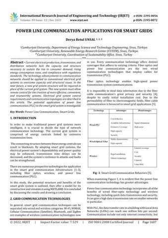
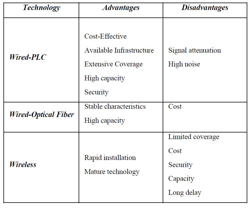
Fig -1:SmartGridCommunicationBehaviors[5].
WhenexaminingFigure1,itisevidentthatthepowerline communicationtechnologyhasgreateradvantages.
Powerlinecommunicationtechnologyincorporatesallofthe benefits of wired fiber-optic technology and wireless technology,includingquickdatatransmissionandsecurity. Itcangiveahighdatatransmissionrateonsmallernetworks inparticular.
WithPLC,thedatatransferrateinabuildingwithLocalArea Networks (LANs) can reach one million bits per second. Communicationincludenotonlyinternetconnectivity,but
2022, IRJET | Impact Factor value: 7.529 | ISO 9001:2008 Certified Journal |

International Research Journal of Engineering and Technology (IRJET) e-ISSN: 2395-0056
alsoanydevicesconnectedtothenetworkthroughpower line.
PLC can be used to manage distribution line activity and passivity. This is particularly important for substations locatedinlocationswithoutacommunicationinfrastructure [1],[5].
Typically,PLCtechnologyutilizesdatatransferonmedium andlowvoltagepowerlines[6].
PLCutilizesexisting wire, makingitsuitedforHomeArea Networks(HANs)andNeighborhoodAreaNetworks(NANs) [7],[8].
DifferentPLCtechnologiesutilizedistinctfrequencybands andsupportvariousdatatransferrates.BroadbandPower LineCommunication(BPLC)andNarrowbandPowerLine Communication (NPLC) are two PLC data communication systems(NBPLC).
PLCtechnologyistypicallyemployedforthetransferoflow and medium voltage power supplies. Establishing transmissionwithvariablevoltagelevelsisquitechallenging duetothelargenumberofsystemcharacteristics,including wiresizesandelectricalparametersathighfrequencies,that affectsystemefficiency.
Asnoiselevel,signalattenuation,impedancematching,and frequencyaretime-dependentvariables,sophisticatedsignal processing and channel coding can lessen the channel's disruptiveeffects.
In PLC applications, the communication signal must be providedwithgreatestefficiency.Otherwise,transmission datalossratescanberathersignificant.
Despite being cost-effective options for smart grid applications,PLCenvironmentsprovidesignificantproblems tothereliabilityandperformanceofcommunicationsystems duetoattenuation(transmissionorrouteloss)[1],[5].
Forthesereasons,newPLCsystemmodelingisbuiltusing Matlab Simulink and parameters of power lines, which include impedance, capacitance and inductance, were evaluatedwithinfluenceonattenuation. Fig.2depicts the PLCsystem'sgeneralinfrastructurediagram.
The attenuation is calculated with matlab design model as 20log10(Vtransmit/Vreceive)indecibels.
It has been measured by broadcasting a signal with a constantsinewaveamplitudeatasubstationwithMVandLV values[9],[10].Sinewaveisasignalthatbeginsataspecific frequency and increases (or decreases) the frequency continuouslyuntilitreachesthefinalfrequency.
Different portions of the sine wave are attenuated differentially,andthereceivedsignalprovidesameasureof thefrequencyresponseofthechannel[10-22].
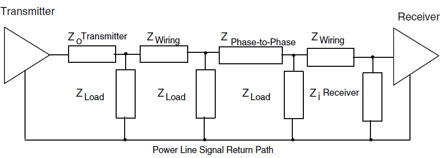
Inthisstudy,theamplitudeofthetransmittedsignalwasset to10V(into50Ohms)andtherangeofthesinewavewas tuned to the desired frequency band. Figure 3 depicts the modelforattenuationcalculation
Fig -2:PowerLineCommunicationSystemBlocks.
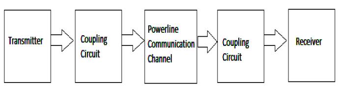
Fig -3:PLCAttenuationModel.
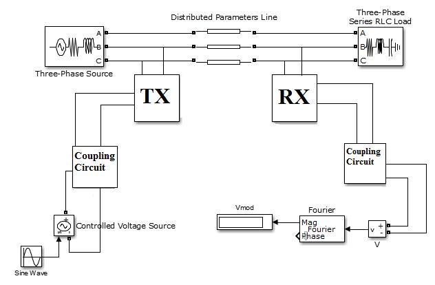
The methodologies described in [9], [20], and [21] were applied in the construction of the new power line communicationsystemmodel(showninFig.4).Ourmodel aims for minimal loss and resemblance to the actual transmissionline[1],[5].
Thecouplingfilter,TransmissionCircuit,andReceiverCircuit models make up the PLC system model. The overhead mediumvoltageandlowvoltagedistributionlinesaretested usingatransmissionlineofsetlength.
ThesimulationresultsofthePLCsystemarethenobtained for various line lengths in MV-to-LV and LV-to-MV communicationsituations.
Designingmodel'stransmissionlineparametersarederived fromIEEEandCENELECstandards[11],[17],and[22]This modelyieldssuperiortransmissionoutcomesincomparison tootherinvestigations.
AfterestablishingthemosteffectivemodelforHV-MV,MVMVandLV-LV,theoutcomesareanalyzed.
ThenaddingHV-MV,MV-LVandLV-MVpowertransformers to the distribution line, the model was modified with standards, the results were analyzed after that results are comparedfromtheauthorspaststudies[5].
Volume: 09 Issue: 12 | Dec 2022 www.irjet.net p-ISSN: 2395-0072 © 2022, IRJET | Impact Factor value: 7.529 | ISO 9001:2008 Certified Journal | Page1608
International Research Journal of Engineering and Technology (IRJET) e-ISSN: 2395-0056
Thisstudyexaminestheresultsandalsoaddedtheresultsof HighVoltage.
On this model, it is evident that the MV transmission performsgivesbestresultsthantheHVorLVtransmission.
Fig -4:PowerLineCommunicationSystemModel.
Inthefirstconfiguration,thesignalwastransmittedinHV and transmitted in MV. In this model, line parameters derivedfromIEEEandCENELECstandards[11],[17],[22], and[23]wereutilized.
HV transmitted MV received PLC transmission system attenuationvaluesresultsindicatea minimumattenuation valueof118.99dBatafrequencyof327kHz,whichisless than55dBinthefrequencyrangeof327kHz10kHz.
Inthesecondconfiguration,thesignalwastransmittedinMV and received inLV.In thismodel,line parameters derived fromIEEEandCENELECstandards[11],[17],[22],and[23] wereutilized.
MV transmitted LV received PLC transmission system attenuation values. The results indicate a minimum attenuation value of 18.89 dB at a frequency of 131 kHz, whichislessthan28dBinthefrequencyrangeof131kHz10 kHz.Theseresultsaresimilartopastresearches.
Inthethirdmodel,thesignalwastransmittedandreceived usingLVandMV,respectively.Inthismodel,lineparameters derivedfromIEEEandCENELECstandards[11],[17],[22], and[23]wereutilized.
Theresultsindicateaminimumattenuationvalueof9.53dB at a frequency of 128 kHz, which is less than 10 dB in the frequencyrangeof128kHz10kHz.
Advancedcommunicationtechnologyisa crucial necessity for the development of the smart grid. Choosing the necessary communication technology for smart grid applications is now the subject of continuous debate. This articleexaminessmartgridcommunicationtechnologiesand theirneeds,aswellasthepowerlinecommunicationsystem forthesmartgridsystem.ToanalyzethebehaviorofPLCfor smartgridapplications,anewPLCsystemmodelisbuiltand researchedtodeterminetheattenuationfactors,suchasline length or output voltage amplitude, that influence the calculations. The simulation results of the PLC system are thenobtainedforvariousfrequenciesandfixedlinelengths in MV transmitted- LV received and LV transmitted- MV receivedcommunication.Accordingtosimulationresults,the attenuation increases with frequency when a signal is transferredfromamediumvoltagetoalowvoltagenetwork, butdecreaseswithfrequencywhenasignal istransmitted from a low voltage to a medium voltage network. The attenuationvaluesofMVtransmissionlinesareoptimalfor powerlinecommunicationapplications.
[1] S. Guzelgoz, “Characterizing Wireless and Power line Communication Channels with Applications to Smart Grid Networks ” PhD Dissertation, University of South Florida, 2011
[2] A. B. M. Shawkat, "Smart Grids; Opportunities, Developments,andTrends",IEEETransactions2013-978-14471-5209-5
[3]V.K.Sood,D.Fischer,J.M.Eklund,T.Brown,“Developinga communicationinfrastructurefortheSmartGrid”,pp.1–7, ElectricalPower&EnergyConference,EPEC,IEEE,2009
[4] IEEE Std.802.16, “IEEE Standard for Local and Metropolitanareanetworks,”2009
[5]D.B.Unsal,T.Yalcinoz,“ApplicationsofNewPowerline Communication Model for Smart Grids.” International Journal ofComputerandElectrical Engineering Volume 7, Number3,June2015
[6] R. Ma, H. Chen, R. Huang, W. Meng, "Smart Grid Communication: Its Challenges and Opportunities" IEEE TransactionsonSmartGrid,vol.4,issue1,pp.36-46
[7]N.Ginot,L.IREENA,F.Nantes,M.AMannah,C.Batard,M. Machmoum,"ApplicationofPowerLineCommunicationfor DataTransmissionOverPWMNetwork",IEEETransactions SmartGrid,pp.178-185,2010
Volume: 09 Issue: 12 | Dec 2022 www.irjet.net p-ISSN: 2395-0072 © 2022, IRJET | Impact Factor value: 7.529 | ISO 9001:2008 Certified Journal | Page1609
International Research Journal of Engineering and Technology (IRJET) e-ISSN: 2395-0056 Volume: 09 Issue: 12 | Dec 2022 www.irjet.net p-ISSN: 2395-0072
[8] G.Bumiller, L. Lampe, H. Hrasnica, "Power line communication networks for large-scale control and automation systems" CommunicationsMagazine, IEEE, pp 106-113
[11] IEEE Std 1901™-2010-IEEE Standard for Broadband over Power Line Networks: Medium Access Control and PhysicalLayerSpecifications
[12]M.Korki,N.Hosseinzadeh,H.L.Vu,T.MoazzeniandC. H.Foh,"AChannelModelforPowerLineCommunicationin theSmartGrid,"PowerSystemsConferenceandExposition (PSCE),2011IEEE/PES,pp.1-7,2011.
[13] NIST framework and roadmap for Smart Grid interoperabilitystandards,Release1.0
[14]F.Aalamifar,Viabilityofpowerlinecommunicationfor smartgridrealization,Ms.Thesis,Queen’sUniversity,2012
[15]A.Cataliotti,G.Tinè"OntheModelofMVPowerLine Communication System in the case of Line to Line transmission",XIXIMEKOWorldCongressFundamentaland AppliedMetrology,,Lisbon,Portugal,September,2009
[16]EchelonCorporation,"LonWorksPLT-30A-BandPower LineTransceiverModule,User’sGuide",Version1.3.
[17]EN50065-1:1991Signallingonlow-voltageelectrical installationsinthefrequencyrange3to148.5kHz Part1: Generalrequirements,frequencybandsandelectromagnetic disturbances; Amendment A1:1992 to EN 50065-1:1991; Amendment A2:1995 to EN 50065-1:1991; Amendment A3:1996toEN50065-1:1991.
[18]P.P.Parikh,M.G.Kanabar,T.S.Sidhu."Opportunitiesand Challenges of Wireless Communication Technologies for Smart Grid Applications" IEEE Power and Energy Society GeneralMeeting,pp.1-7,July2010.
[19] A. Cataliotti, A. Daidone, G. Sanacore, G. Tinè "CharacterizationofMediumVoltagecablesforpowerlines communications", 15th IMEKO TC4-International Symposium on Advanced of Measurement Science, Iasi, Romania,September2007.
[20]M.Zimmermann,K.Dostert,"Amultipathmodelforthe powerlinechannel,"IEEETransactionsonCommunications, vol.50,no.4,pp.553-559,April2002.
[21]A.Cataliotti,D.DiCara,G.Tinè,"ModelofLinetoShield Power Line Communication System on a Medium Voltage Network", Instrumentation and Measurement Technology Conference,2010IEEE
[22] IEEE Standards 643TM IEEE Guide for Power Line CarrierApplications.8June2005
[23] RG7H1R Elektrotek Medium Voltage cables. www.elettrotekkabel.com
2022, IRJET | Impact Factor value: 7.529 | ISO 9001:2008 Certified Journal |