1Student, Bachelor of Engineering (Mechanical Engineering), Dr.J.J. Magdum College of Engineering, Jaysingpur 416 101 (Maharashtra) (India) ***
Description: Itisafootoperatedpneumaticcylinder.Afterapplyingthe force on foot pedal compressed air from compressor will applyforcetothepiston.Thiswillcauseheatingdiscmove down and apply heat and pressure on lid of plastic cover. Duetoheatandpressuretheplasticandaluminiumfoillid willgetstucktogetherandcupwillgetsealed.
1
International Research Journal of Engineering and Technology (IRJET) e ISSN: 2395 0056 Volume: 09 Issue: 01 | Jan 2022 www.irjet.net p ISSN: 2395 0072 © 2022, IRJET | Impact Factor value: 7.529 | ISO 9001:2008 Certified Journal | Page1225
1.INTRODUCTION
Key Words: Pneumatic, Cup, Seal, Production, Manufacturing,Market,Efficiency.
3. More rugged: Cylinders can be stalled indefinitelywithoutdamageResistanttoimpacts.
Mr. Shreyas Satish Vathare
PNEUMATIC CUP SEALER
Ourunitcontains:1)Pneumaticcylinder 2)FRLunit 3)Footpedal(3/2)valve 4)FCV&NRV Heatingdisc&Heatingcoil Frame 7)Controlpanel
5)
6)
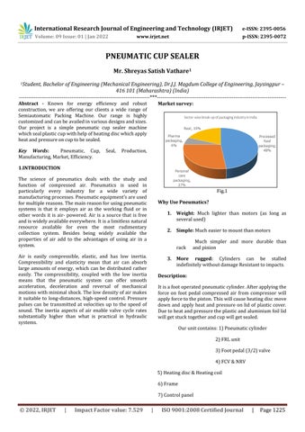
Market survey: Fig.1
Why Use Pneumatics?
1. Weight: Much lighter than motors (as long as severalused)
2. Simple: Mucheasiertomountthanmotors
Much simpler and more durable than rack andpinion
Abstract - Known for energy efficiency and robust construction, we are offering our clients a wide range of Semiautomatic Packing Machine. Our range is highly customizedandcanbeavailedinvariousdesignsandsizes. Our project is a simple pneumatic cup sealer machine whichsealplasticcupwithhelpofheatingdiscwhichapply heatandpressureoncuptobesealed.
The science of pneumatics deals with the study and function of compressed air. Pneumatics is used in particularly every industry for a wide variety of manufacturingprocesses.Pneumaticequipment’sareused formultiplereasons.Themainreasonforusingpneumatic systems is that it employs air as the working fluid or in other words it is air powered. Air is a source that is free andiswidelyavailableeverywhere.Itisalimitlessnatural resource available for even the most rudimentary collection system. Besides being widely available the properties of air add to the advantages of using air in a Airsystem.iseasily compressible, elastic, and has low inertia. Compressibility and elasticity mean that air can absorb large amounts of energy, which can be distributed rather easily. The compressibility, coupled with the low inertia means that the pneumatic system can offer smooth acceleration, deceleration and reversal of mechanical motionswithminimalshock.Thelowdensityofairmakes it suitable to long distances, high speed control. Pressure pulses can be transmitted at velocities up to the speed of sound. The inertia aspects of air enable valve cycle rates substantially higher than what is practical in hydraulic systems.

International Research Journal of Engineering and Technology (IRJET) e ISSN: 2395 0056 Volume: 09 Issue: 01 | Jan 2022 www.irjet.net p ISSN: 2395 0072 © 2022, IRJET | Impact Factor value: 7.529 | ISO 9001:2008 Certified Journal | Page1226 8)Pipesandconnectors Pneumatic Cup Sealer: These tools are durable and available in various specifications to meet the diverse requirements of these our Productclients.features: o Economical o Robust o Flexible o Portable o Lowmaintenance o Easytooperate o Easytoclean o Quickinstallation o Easytoassembleanddisassemble Part List: 1. PneumaticcylinderDA 2. FRLunit 3. Footpedal(3/2) 4. Aluminiumheatingdisc 5. Heatingcoil 6. Controlpanel 7. Hoses 8. Connectors 9. FlowControlValve 10. Checkvalve 11. Frame 12. Compressor 13. Cupandlid Part PNEUMATICDetails: CYLINDER DOUBLE ACTING: Pneumaticcylindersaremechanicaldeviceswhichusethe power of compressed gas to produce a force in a reciprocatinglinearmotion.Fig.2
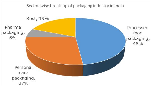
An air line filter cleans compressed air. It strains the air and traps solid particles (dust, dirt, rust) and separates liquids(water,oil)entrainedinthecompressedair.Filters are installed in the air line upstream of regulators, lubricators, directional control valves, and air driven devicessuchascylindersandairmotors. Fig.3
FRL UNIT:
Airleavingacompressorishot,dirty,andwet whichcan damage and shorten the life of downstream equipment, such as valves and cylinders. Before air can be used it needstobefiltered,regulatedandlubricated.

FOOT PEDAL (5/2): Theyareusedtoregulateairflow,wherenecessary. Foot pedal is nothing but 5/2 directional control valve operatedmechanicallybypressingitbyfoot.
●Regulateflowofairintoandoutofacylinder
● seems to regulate air flowing in both directions, butonedirectionisrestrictedalittlemore.
●Usedtocontrolspeedofapneumaticcylinder
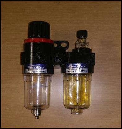
Heating disc: Heating disc is made of aluminium cast. First, we made a wooden pattern with 5mm extra for tolerance. The finisheddiscwasofsizeasfollowing Diameter:130mm Height:20mm Bossdia:30mm Bossheight:35mm Fig.4 This aluminium disc contains slots for wire, deep hole for heating coil, Allen keys to hold tight, thread in boss for attachingcylinderrodend.
Hose are career for air toward all pneumatics the Diametercomponents.ofhoseis8mm.
Frame: Frame is used to support all components and equipments used in total unit the frame supports cylinder, FRL unit, footpedalandslidingdiscinwhichcupistobeholded.
Heating disc: Controlpanelconsistofthermostat.Acompatiblerheostat isfittedinboxwithindicatingLEDandcalibratedscalefor adjustingtemperature Hoses: Hoses are nothing but pipe made o0f high strength and flexiblerubbermixedplastici.e.,polyurethane.
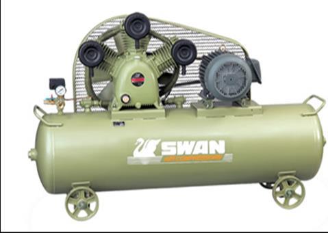
Compressor: Compressor is main powerhouse of total pneumatic system
TotalframeismadeofM.S.Fig.5
International Research Journal of Engineering and Technology (IRJET) e ISSN: 2395 0056 Volume: 09 Issue: 01 | Jan 2022 www.irjet.net p ISSN: 2395 0072 © 2022, IRJET | Impact Factor value: 7.529 | ISO 9001:2008 Certified Journal | 1227
Connectors: Connectors are small components which are used to connectpneumaticcomponentsandhosestoeachother.
Weused8mmpneumaticconnectorsforalljoints
Flow Control Valve: Flowcontrolvalvesareusedtocontrolflowofairentering or exitingthepneumaticcylinder.
● If used, attach directly to cylinder (only one end needed)
Page

Certified Journal | Page1228
5. Then we connected Pneumatic cylinder, FRL unit,5/2DCvalve,FCV,NRV,informofmeter out circuit with the help of hose and connectors and finally connected it to
3. Economical.
International Research Journal of Engineering and Technology (IRJET) e ISSN: 2395 0056
ADVANTAGES:
10. Thentherectangularplateispull.
2. Therectangularplateispulledbyusinghand.
5. Then the rectangular plate is push to the assembly.
Fig.6
Construction: 1. The total frame is erected by using angle, square pipes, strips of M.S. and weldingprocess.
1. Firststartthecompressor.
8. Atthesametimebyusingtheheatingcoilthe temperatureofthediscisincreased.
2. Kept the pneumatic cylinder at the top position. And tightened it to supporting angles by its own end threading at required position.
4. Before attaching heating disc to cylinder we placed heating coil in to the disc and tightened it with Allen key. Both connecting wiresofheatingcoilareconnectedtocontrol panel.Alsotakenearthingoutofheatingdisc.
11. Removeglassfromplate.
9. That means by using the pressure and temperature the glass cover is fitted on the glass.
● Tubing attached simply by pushing it into connectorIfyouhavealeak,trycuttingoffthelast couple centimeters of tubing; if it is damaged, it will not seal properly To detect leaks, put soapy water on suspect connections and watch for bubbling.
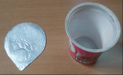
Cup and Lid:
4. After that the glass cover is placed at top of theglass.
Volume: 09 Issue: 01 | Jan 2022 www.irjet.net p ISSN: 2395 0072 © 2022, IRJET | Impact Factor value: 7.529 | ISO 9001:2008
7. The circular disc is applying the sufficient pressureontheglasscover.
Fittings:
Thencompressorarranged control panel and placed slidingdiscintoframeandtooktrial.
●PutTeflontapeonall threadstoensurea good sealdonotputtapeonfirsttwothreads,asitmay comelooseandclogupavalve
Cup is made of food grade plastic and lid is made of food gradealuminiumfoil. Fig.7
Working:
3. After that the glass which we want to pack is insertedintherectangularplate.
3. The circular heating plate is attached to piston end of the pneumatic cylinder by means of threads on piston rod and internal threads on boss of disc bye fastening and providedalocknut.
1. Minimumtimerequired 2. It’sasemiautomaticprocess.
6. Then press the foot operated valve by using foot.
CONCLUSION:
BIOGRAPHIES: Mr. Shreyas Satish Vathare. (BachelorofMechanicalEngineering, Dr.J.J.Magdumcollegeofengineering, Jaysingpur(416101),MH,India)
Location: Sangli(416416),MH,India
International Research Journal of Engineering and Technology (IRJET) e ISSN: 2395 0056 Volume: 09 Issue: 01 | Jan 2022 www.irjet.net p ISSN: 2395 0072 © 2022, IRJET | Impact Factor value: 7.529 | ISO 9001:2008 Certified Journal | Page1229 4. Notrequiredtechnicallabor. 5. Sizeofmachineissmall. 6. Nothigherelectricityrequired. 7. Small to medium sized cup or glass can be packed. 8. Variousshapedcupscanbepacked 9. Robust 10. Flexible DISADVANTAGES 1. Requirescompressor. 2. Laborrequired. 3. Newplateisrequiredfornewshapeofcup. Fig.8: Final Product
The science of pneumatics deals with the study and function of compressed air. Pneumatics is used in particularly every industry for a wide variety of manufacturingprocesses.Pneumaticequipment’sareused formultiplereasons.Themainreasonforusingpneumatic systems is that it employs air as the working fluid or in other words it is air powered. Air is a source that is free andiswidelyavailableeverywhere.Itisalimitlessnatural resource available for even the most rudimentary collection system. Besides being widely available the properties of air add to the advantages of using air in a Easysystem.andmoreEfficient.