International Research Journal of Engineering and Technology (IRJET) e ISSN: 2395 0056 Volume: 09 Issue: 01 | Jan 2022 www.irjet.net p ISSN: 2395 0072 © 2022, IRJET | Impact Factor value: 7.529 | ISO 9001:2008 Certified Journal | Page1096 Design and Development of Pneumatic Scissor Lift Ajay More1 , Vivek Koli2 , Rushiprasad Watpade3, Pratik Chaudhari4, Mr. Ravindra Ghogare5 1Student, Mechanical Engineering, MVPS’s KBT College of Engineering, Nashik, Maharashtra, India 2Student, Mechanical Engineering, MVPS’s KBT College of Engineering, Nashik, Maharashtra, India 3Student, Mechanical Engineering, MVPS’s KBT College of Engineering, Nashik, Maharashtra, India 4Student, Mechanical Engineering, MVPS’s KBT College of Engineering, Nashik, Maharashtra, India 5Assistant Professor, Mechanical Engineering, MVPS’s KBT College of Engineering, Nashik, Maharashtra, India *** Abstract - The Scissor lifts are a type of mechanism that allows for vertical displacement of some load, thorough the use of linked and folding supports in a crisscross “X” pattern, referred to as a pantograph or simply a Scissor Mechanism. Scissor lifts are widely used in industrial applications and also a staple design element in competitive robotics. Each arm of the crosses is called a ‘scissor arm’ or ‘scissor member’ The upward motion is produced by the application of force by some actuators usually Hydraulic, Pneumatic or mechanical Key Words: Low cost application1, Scissor Lift2 , Pneumatics3, Actuator4, Mechanical Advantage5 1.INTRODUCTION Lift is a very simple device or mechanism used for raising any elements or objects or load from ground level to a specific height to perform a particular task or work with maximum possible load carrying capacity and minimum effortsofaworkman.Togetthis,werequiredmaterialwith higher strength, hydraulic components such as wheels, hydraulics cylinders, etc. all the researchers attempt to optimize all these parameters according to the all requirements.Inthisprojectandresearch,wetriedtothink about lots of different research papers containing the research&analysismadeonscissorliftmechanismevaluated thedesignandanalysisoftheseScissorLift 1.1 PROBLEM STATEMENT
Many industries require periodic maintenance of some machines, overhead cranes, light system, electrical maintenance, etc. So, all of this component is not within human reach from maintenance point of view. So, use of ladder,ropesarebroughtinconsiderationformaintenance work. So, to overcome this situation we are constructing Pneumaticliftingmachine. WeareselectedtoconstructPneumaticLiftingMachine ratherthanHydraulicbecause,insomecaseswecan’tafford thehydraulicssystembecausewewanttouseitforsmaller scalework.So,it’sawasteofmoneytousehydraulicmachine for maximum 150 to 200 kg load, Pneumatics are ideally suitableforthat. control
valve (5/2 DCV) 3.Pneumatic connector 4.Pneumatic pipes and hoses 5.Structure frame 6.Roller wheels
2. LITERATURE REVIEW
Prushotam & Apsad Ali, done the work on, Design and AnalysisofHydraulicScissorLiftbyUsingANSYS,thispaper mainlytellsaboutforcefollowinguponthepressuredriven scissorliftwhenitiscontractedandexpanded.Inmostofthe caseshydraulicliftisusedtoliftheavyobjectslikevehiclein automobileindustry.InplanningamachineMaterialchoice isakeyjobandfurthermorechanges onafewfactors,for instance,unsteadyquality,qualityobstructionwhichatlong lastincreases thelifeofscissorlift.Theplanisperformedby considering pressure driven hydraulic scissor lift as a convenient,conservativeandmuchappropriateformedium andhighlevelofloadcarryingmechanisms. Plan of water powered framework scissor lift is finished utilizingCATIAV5R20withappropriatedemonstratingand importedtoANSYSV17.0forexaminationandstimulation. Asresult,thestaticobservationofthepneumaticscissorlift incorporates add up to imbalanced force, load, Equivalent pressure,weightwasperformedinANSYSandeveryfusion add up to defacement load, Equivalent pressure, force, weight was performed in ANSYS and every single reliable parameterwereanatomizedwiththeendgoaltocheckthe similarityoftheoutlines.Thecomputationalestimationsof threedifferentmaterials,forexample,auxiliarysteel,carbon fibreandAluminiumAlloyarelookedatforbestoutcomes. From all the experimental analyses performed, it can be clearlyseenthatCarbonFibrematerialhasextremelylow weight than other conventional materials being use for manufacturingofmachineslikescissorlifts.Thedesignand manufacturing of a remote work platform lifted by a hydraulic cylinder was carried out to meet the need of designstandards
1.2 COMPONENTS INVOLVED 1.Pneumatic cylinder 2.Flow

Toobtainhighstrengththeshearing toolshouldbeheattreated.
3.2. Platform Structure: If center of gravity of loads moves from the center (distributedevenly)toanyedge(eccentricallyloaded)ofthe platformthenplatformbendingmayoccur.Throughlifting of scissor lift, the rollers roll backs towards the platform hingesandcreateanoverhungandunsupportedparttothe baseplatformassembly.Highcentral loadsappliedtothis unsupportedendsoftheplatformcancausebendingofthe baseplatform.
Legdeflectionduetobendingiscausedduetostress.Asthe lengthincreasesofscissorlegitismoredifficulttobalanceit and stress concentration point also changes. To improve resistance to deflection leg strength is increased via increasing strength of leg material and also using high strengthmaterial,butcancreateapotentiallyundesirable increasedcollapsedheightofthelift.
GaffarMomin,KaranDalvi, RohanHatti,RohitDevare,Faisal Bargi,,completedtheworkon,Design Manufacturingand InspectionofHydraulicScissorLift,wherethesubsequent paperdescribesthedesign,constructionaswellasanalysis ofahydraulicscissorlift.Conventionallyascissorlift isused forliftinggainaccesstogototheundersideofthevehicle,to lift up the body to maximum height, and many other applications Also such as lifts can be used for various purposes like maintenance , cleaning and many material handling work operations . It can be built of mechanical, pneumatic or hydraulic type. The detailed overall design explained inthispaperisdevelopedkeepinginmindthat the lift can be operated by mechanical means by using pantograph so that the overall cost of the scissor lift is reduceasmuchaspossible.Inourcaseourliftwasrequired tobedesignedinsuchawaythataportableandalsowork withoutconsuminganyelectricpowersupplysowedecided to use a hydraulic hand pump to pressurized the cylinder Alsosuchdesigncanmaketheliftmorecompactandmuch suitableformediumandhighscaleoperations.Inlast,the analysisofthescissorliftwascompletedinANSYSdesigning software&allresponsibleparametersweredemonstratedin order to check the compatibility and requirement of the designvalues.
3. 3.1.CONSTRUCTIONScissorarms:
OurprojectisonPneumaticcontrolsystem.ThePneumatic piston cylinder is an actuator which converts pressure of compressed air to displacement. When their is pressure difference between both the ends of piston cylinder to neutralizethesethedisplacementofpistonrodoccurs.The speed of these motion is directly proportional to the pressuredifferencebetweenbothend.Thereisatwoportin double acting cylinder through which the supply of air is
International Research Journal of Engineering and Technology (IRJET) e ISSN: 2395 0056 Volume: 09 Issue: 01 | Jan 2022 www.irjet.net p ISSN: 2395 0072 © 2022, IRJET | Impact Factor value: 7.529 | ISO 9001:2008 Certified Journal | Page1097
industrialrequirements andtheapplicationofpneumatic scissorliftareelaborated.Various3Dsoftwareisusedfor modelling.ANSYSsoftwareisusedtocarrytheanalysisof this mechanism. Amalgamation of different material and their results are given which leads to proper material selectiontomeetthestandardsystemrequirements.
3.4. Pinned Joints: Scissorliftsareattachedorjoinedatallend points,andeach pin runsthroughclearancebetween OuterDiameterofthe pinandtheInnerDiameter ofitsclearancebushingorhole. The more scissors pairs or scissor mechanism that are assembled on top of each other, there are more pinned connections to accumulate movement or deflection, when compressing allthesedesignedclearances.
Ankita Chimote, Prof. Vinod Bhaiswar, Ass.Prof. Vishal Kshirsagar,donetheworkon,ReviewonIndustrialScissor Lift, this paper evaluated the design and analysis of industrial Scissor Lift. It gives the brief overview and description ofitsalltypes,systemrequirements,working & design methodologies. This paper examine the need of designingjacktoovercomesystemrequirementbyselecting appropriatedrivesystemaspertheapplication.Thispaper gives the design methodologies of pneumatic scissor lift. Also,
3.3. Base Frame: Basicallythebaseframeismountedtothefloorandshould notexperienceanytypeofdeflection.Becauseitsfixedtoits position for stability of whole mechanism. In such cases wherethescissorsliftismountedtoanportableframe,the baseframemustberigidlysupportedfrombelowtosupport thepointloadingcreatedbythetwoscissorlegrollerand thetwoscissorsleghinges.
Thedesign,development&manufacturingofa remoteworkplatformliftedupbyahydrauliccylinderwas carried outin properway bymeetingthe requireddesign standardsnorms.Theremoteworkplatformisoperatedby hydraulic cylinder which is operated by a hand pump ergonomics Of a workman working in the workshops or compony isaresponsibilityofanorganizations.operators comfort is also an important thing. Hence, by making this hydraulicliftweimprovedthecomfortleveloftheoperator workingonthecoldforgingmachineinhisworkplace Ourmainmotivebehinddevelopingthislifterwasproviding comfort to the operator and material handling. This was consideredasaradicalimprovementintheproductivityby thecompanyorindustry.Wecandesignscissorliftforhigh load also if a proper High capacity hydraulic cylinder is considered. The pneumtic scissor lift mechanism is very simple in operation and does not require regular maintenance. Itcanliftveryheavyandhigh loads.Themain constraintofthisdeviceisithashighinitialvalue,buthasa verylessoperatingcost.
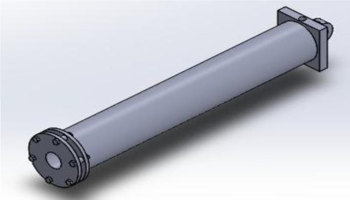
3.5. Pneumatic Cylinder
5. 5.1DESIGN.Design of Base Frame: Thebaseframeinascissorliftonlyprovidesproperbalance and stability to the structure. Considering the size constraints,thedimensionsofthebaseframeweretakenas follows. Also, it had been considered that not much of the stressesaredevelopedinthebaseframe.
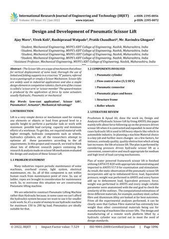
Fig 1: Pneumatic Scissor Life
reversed in direction to cause displacement in both direction.Cylindersofthoseliftarenearlyflatwithineachof thescissorslegsoncetheliftisabsolutelyloweredatbottom andshouldproduceinitialhorizontalforcesuptofivetoten foldsof theamountoftheloadonthebottombaseplatform of scissors lift because of the mechanical disadvantage of theirmachinegeometries. Inresultofthat,therearelotsof stressesandensuingdeflectionplacedonthescissorsinner legmemberormembersthataredesignedtoimpedethese cylinder forces. As already mentioned higher than any alterationincolumnlengthoftheelevating actuator,results vertical lift movement is multiply by 5 of that amount of change 3.6. Pneumatic Circuit: Alltrappedairshouldbeforthepneumaticcircuitthrough approvedâ€oebleedig―procedures–airisextremely compressible andis rarely theculpritonce a scissorslift over compresses below load and otherwise bounces throughoutoperations. Air as a fluid can compress slightly lower pressure. And because of there's assosiate nearly ten bar of operating maximumoflifttraveltocylinderstrokeformanyscissors lift designs , there is a ensuing ratio of scissors lift compression to cylinder compression. All high pressures, changeablehosingisprobablygoingtodegreeofhosebulge oncethesystempressureisexaggerated.Systempressure fellssignificantlyowingtothisexaggeratedhosevolume,and therefore the scissors table wedging under load upto the most system pressure is re established. And as with compressibility,theresultingliftmovementisfivefoldsthe modificationinoilcolumnheightwithinthehose. 3.7. 5/2 Valve DCV: Inourmachine,weusedtwo5/2valvetodirecttheflowof compressed air on the either side of piston for the reciprocatingmotionofsame.Thedirectionalcontrolvalve mustdiresttheflowfromthecompressoreithertoportAor portB.Thefluidexhaustedbythecylindermustbedirected fromtheotherporttobacktotank.Theabovegivenvalve has2positions and5ports sothat’swhyitiscalledas5/2 directionalcontrolvalve.Valvesarerequiredtocontrolthe flow rate, pressure and direction of the fluid. These pneumaticsystemsarecomparativelylowpressuresystems. Pneumatic valves are made from cheaper materials like aluminiumandpolymersandarecheapertomanufacture. TheDCVmustgivetheflowfromthecompressortoportA orB.Thevalveweusedandshownhasfiveportsandtwo positionssoitisdesignatedasa5/2DCV.Itisnotedthatthe third position in a 5/2 valve is center position. The air controlmechanismwithinthe5/2 DCV ismoved towards thecenter positioninsidetheDCVbyone internalspring valveactuatorfromtwoofthem.Thespringis locatedinside thevalveateveryendoftheinternalspool.
Fig 5.1: Base Frame
4. WORKING Aframeissupportingallpneumatics&scissormechanismof amachineasshowninfig.4.1Hereweusedacompressorfor agenerationofcompressedair.Acompressedairissupply tothedoubleactingcylinderbymeansofpneumatichose pipe&5/2Directioncontrolvalve.Thescissormechanismis provided at end of the pneumatic cylinder rod. When compressed air is supply by the DCV to double acting cylinderduetopressure&forcecreatedbycompressedair causesrisingactionoftheload.Heretheadvancementofthe scissor mechanism is carried out in the upward and the downward direction using the pneumatic double acting piston and cylinder unit arrangement with the hand lever operatedDCV(Directioncontrolvalve).Inthismachinethe highpressurecompressedairisusedastheworkingfluidfor thetransferofpower,forceandthemotiontothesystem. Wedevelopedamodelofthepneumaticscissorlift.Inthis mechanismwe usedpistoncylinder withsmaller stroke. Butifwewanttodevelopapneumaticscissorliftthatisto beusedinthefactoryfloor,wecanusethepistoncylinders with higher stroke and Bore diameter to get the extra movementsandforceofthepneumaticscissorlift.Also,for highloadliftingcapacity.
International Research Journal of Engineering and Technology (IRJET) e ISSN: 2395 0056 Volume: 09 Issue: 01 | Jan 2022 www.irjet.net p ISSN: 2395 0072 © 2022, IRJET | Impact Factor value: 7.529 | ISO 9001:2008 Certified Journal | Page1098
ThetotalloadactingonthecylinderconsistsofMasstobe putonlift=100kg=981N=1000N. Forcylinderdesignweusepressureequalto6bar i.e. 0.6N/mm²Therefore, Therefore, we selected 50 mm diametric cylinder.
1.work:Duringworkingitisfoundthatthenaturalfrequencyoflift should not be equal to the external excitation frequency hencenovibrationinthelift.
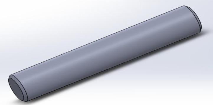
A=Crosssectionalareawhichisinshear mm² 5.3 Pneumatic Cylinder: Thepneumaticcylinderismountedininclinedposition.
2. A portable work platform pneumatic scissor lift is designedforhighloadresistance.
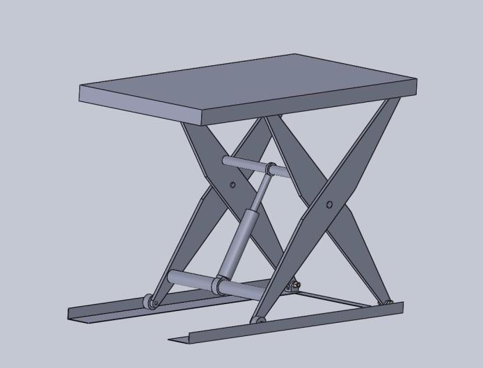
Fig 5.2: Pin Pingoesundershearstress, Therefore, we selected 5mm diametric pin. here, τ all=allowableshearstressinpin(N/mm2) =Totalforceappliedonpin(N)
ACKNOWLEDGEMENT
5.2. Design of Pin: Pinisthemostimportantfactorinscissorliftingmechanism. It connects the top and bottom frame because of that we have to use pin with some extra higher strength in it . In scissorlifter,pinunderwentthe shearstress.Shearstressis aforceperunitcrosssectionalarea.
Wewouldliketotakethisopportunitytothankourinternal guide Prof.R.M.Ghogare for giving us all the help and guidance we needed. We are really grateful to him for his kind support to us. His valuable suggestions were always veryhelpfulforus.
Thefollowingconclusionsaremadefromthiswholeproject
Fig 5.3: Pneumatic Cylinder
6. CONCLUSIONS
International Research Journal of Engineering and Technology (IRJET) e ISSN: 2395 0056 Volume: 09 Issue: 01 | Jan 2022 www.irjet.net p ISSN: 2395 0072 © 2022, IRJET | Impact Factor value: 7.529 | ISO 9001:2008 Certified Journal | Page1099
3.Thepneumaticscissorlift issimpleinuseanddoesnot requireroutinemaintenance.
P


International Research Journal of Engineering and Technology (IRJET) e ISSN: 2395 0056 Volume: 09 Issue: 01 | Jan 2022 www.irjet.net p ISSN: 2395 0072 © 2022, IRJET | Impact Factor value: 7.529 | ISO 9001:2008 Certified Journal | Page1100 REFERENCES [1] Prushotam & Apsad Ali, Design and Analysis of HydraulicScissorLiftbyUsingANSYS,ShodhSangam A RKDF University Journal of Science and Engineering, Vol. 02,No. 01,Feb 2019,Page 12 20. [2] GaffarGMomin,RohanHatti,KaranDalvi,FaisalBargi, Rohit Devare, Design, Manufacturing and Analysis of Hydraulic Scissor Lift, International Journal of Engineering Research and General Science Volume 3, Issue 2,Part 2,MarchApril,2015,pp733:740 [3] ChimoteAnkita,Prof.VinodBhaiswar,Ass.Prof.Vishal Kshirsagar, Review on Industrial Scissor Lift, International Journal For Technological Research In Engineering Volume 6, Issue 8, April 2019,pp. 5395 5396. [4] Anupam Chaturvedi, Prof. Jyoti Mishra, Prof. Parmar Vijay,AnImprovedScissorLiftworkingonLeadScrew Mechanism Aerial Scissor Lift and its Accessories, International Journal of Advance Engineering and Research Development Volume 4, Issue 2, February 2017,pp.89 95 [5] Suraj B, Dhanawade, Shubham S. Bhujbal, Rohan R. Dhane,Prof.RahulR.Narkar,Prof.SangramS.Bhosale, Design,AnalysisandDevelopmentofHydraulicScissor Lift Material loading and unloading , International Journal of Advance Engineering and Research DevelopmentVolume 4,Issue 3,March:2017,pp.214 221 [6] SabdeAbhijitManoharrao,Prof.JamgekarR.S.,Analysis &OptimizationofHydraulicScissorLift,International JournalofEngineeringDevelopmentandResearch,2016 IJEDR|Volume4,Issue4,pp.329 347.
[7] KapatelJainil,PritPatel,RanaMitul, Prof.MihirRana, Prof.JayeshPatel ProposedWorkonScissorLift,IJSRD International Journal for Scientific Research & Development|Vol.5,Issue06,2017,pp.414 416.
[8] M.KiranKumar,J.Chandrasheker,MahipalManda,Dr. VijayKumar,Designand AnalysisofHydraulicScissor Lift,InternationalResearchJournalofEngineeringand Technology,Volume:03Issue:06|June2016 pp1647: 1653. Pentamalla Srinivasulu & Mr. K. Sainath, Design And Analysis Of Scissor Lifiting Mechanism, International Research Journal of Engineering and Technology (IRJET),Volume:06Issue:06|June2019,pp.446 452. Doli Rani, Nitin Agarwal & Vineet Tirth, Design and FabricationofHydraulicScissorLift,MITInternational JournalofMechanicalEngineering,Vol.5,No.2,August 2015,pp.81 87.
[9]
[10]
[11] Mahmut Can Şenel, Cengiz Görkem Dengiz, Kemal Yıldızl,ErdemKoc.DesignandAnalysisofScissorLifting System by Using Finite Elements Method Universal JournalofMaterialsScience6(2)2018,pp.58 63. BIOGRAPHIES Mr.AjayR.More BEMechanicalEngineering MVPS’sKBTCollegeofEngineering Mr.VivekD.Koli BEMechanicalEngineering MVPS’sKBTCollegeofEngineering Mr.RushiprasadR.Watpade BEMechanicalEngineering MVPS’sKBTCollegeofEngineering Mr.PratikChaudhari BEMechanicalEngineering MVPS’sKBTCollegeofEngineering Mr.RavindraGhogare Assistant MechanicalProfessor,Engineering MVPS’sKBTCollegeofEngineering