
International Research Journal of Engineering and Technology (IRJET) e-ISSN:2395-0056

Volume: 09 Issue: 11 | Nov 2022 www.irjet.net p-ISSN:2395-0072
ZVS Circuit based – Cockcroft Walton High Voltage DC Generator
Sujit Kathole1 , Rohan Rooge2 , Ninad Bharambe3***
Abstract - The primary use of high voltage D.C. power supplies is at the industrial level and in research activities, particularly in the field of applied physics. When tested with an A.C. high voltage power frequency of sinusoidal waveform ratherthand.c. voltage, Kuffeletal.discoveredthatthepower supply draws a significant amount of current due to the comparatively large capacitive load in the proven design of high voltage cables (2000). High voltages are produced at power frequency A.C./D.C. switching surge voltages and lightningimpulsevoltagesfor dielectrictestingofhighvoltage equipment. Voltages are raised to several million volts for dielectric testing of high voltage equipment, but currents are loweredtoafewmilliampsandamaximumofoneampere for A.C./D.C. high voltage tests. D.C. high voltage is used in a variety of electrical engineering and applied physics applications,includingelectronmicroscopes,X-ray machines, electrostatic precipitators, nuclear physics particle accelerators, dielectric testing, and more. The dielectric behaviors underallconditionsthattheequipment/apparatus are expected to experience are studied using high voltage equipment. To determine the safety aspects of the working conditions and to make sure that the working margin is neither too high nor too low, tests are carried out at voltages higher than the typical working voltage.
Key Words: High voltage, Cockcroft Walton voltage multiplier, High frequency, Ripple, High voltage, Flyback Transformer
1.INTRODUCTION
Today, there are many devices and instruments requiring high voltages. Typically, a High voltage DC output is often required in various facets of research areas in the field of appliedphysicsandfortestingpurposesinindustries.High voltage is used for dielectric and insulation testing of electrical equipment at power frequency. There are many applications of High voltage DC power in electrical engineeringsuchaselectronmicroscope,x-ray,electrostatic precipitators,particleaccelerators,etc.Dielectricbehaviorof electricalequipmentcanbetestedbygivinghighvoltageDC supplyasaninputtothem,wherethesurvivingcapacityof equipmentcanbetestedatallconditions.Thevoltagegiven to the equipment should be greater than the normal DC voltagetofindouttheequipment’ssustainingcapabilityof voltage and decide the voltage margin for the particular equipment
ThesystemAcircuitthatcreatesDCpoweratahigh voltageisknownasavoltagemultiplierorCockcroftWalton generator. Heinrich Greinacher, in 1919, made a considerablyearlierdiscoveryofthiscircuit.TheBritishand IrishphysicistsJhonDouglasWaltonandEarnestThomsan Walton, who originally utilised this circuit to power their particleacceleratorin1932, are honoured by the circuit's name.Withagreaternumberofstages,CWmultipliersare alsoutilisedinlasersystems,high-voltagepowersupplies,Xray systems, LCD backlighting, traveling-wave tube amplifiers, ion pumps, electrostatic systems, air ionisers, particle accelerators, copy machines, scientific instrumentation,oscilloscopes,televisionsets,cathode-ray tubes, electroshock weapons, bug zappers, and numerous otherhigh-voltageDCapplications.TheCWhasanumberof shortcomingsinactualuse.Theelectricalresistanceofthe capacitors in the lower stages is the main cause of the voltagesoftheupperstagesstartingto"sag"asthenumber of stages is raised. Additionally, as the number of steps is increased while supplying an output current, the voltage ripple quickly grows. The output voltage's ripple content, voltage drop, and voltage regulation are the three main performanceindicatorsoftheCockcroftWaltongenerator. Boththesourcevoltage,orgeneratorinputvoltage,andthe frequency of the AC supply given to the generator's input determinetheseperformancefactors.
In this project, we've tried to increase these performancecriteria byaddingtwocomponentsthatfeed theprimaryCockcroft-Waltongeneratingcircuitwithahigh voltage,highfrequencyACsupply.Theflybacktransformer andthezero-voltageswitching(ZVS)driverarethesetwo parts.TheZVSdriverisanelectroniccircuitthatproduces highfrequency,highvoltageacoutputandissuppliedbya lowvoltageDCpowersupply.Additionally,theoutput'shigh frequencycanbecustomisedbyusingavariablecapacitorat theZVSdriver'soutput.Theflybacktransformerraiseslow voltage, high frequency ac input to high frequency, high voltage. It is a specific kind of transformer capable of handlinghighfrequencyac.
Additionally,inadditiontoenhancingperformance, thesuggestedapproachfocusesoncreatinganeconomical. Thepriceyhighvoltagecapacitorsanddiodesemployedin theCWgenerator'sladdernetworkaccountforthemajority ofthegenerator'scost.Thepriceofthegeneratorrisesasthe numberofstepsgrows.However,byusingfewerstagesto providehighvoltageoutputattheoutputside,thiscostcan be decreased. This is made possible by the addition of a flybacktransformer,whichsupplieshighvoltagetotheCW
*1,2,3Department of Electrical Engineering, University of Mumbai, Maharashtra, IndiaInternational Research Journal of Engineering and Technology (IRJET) e-ISSN:2395-0056
Volume: 09 Issue: 11 | Nov 2022 www.irjet.net p-ISSN:2395-0072
generator'sinput,allowingforthegenerationofhighvoltage DCwithfewersteps.
The proposed model is therefore cost-effective. Since the ZVS is supplied by a low voltage DC supply, this variantcanberunonasmallbattery.Thismakesthemodel easytouse,lightweight,and portable.Becauseofthis,the modelisverypracticalandhelpfulinfieldexperiments.
Advantages and Applications
Advantages of ZVS Circuit Based Cockcroft Walton Generator
Some of the key blessings of ZVS driver-based CockcroftWalton Generator areas follows-
Performance: The Performance parameter of generatordependentofinputpowerfrequencyi.e. ripplevoltageandvoltageregulationarimproved byvictimizationhighfrequencyAC.
High voltage military application (very low frequency radio communication).
2. Review of Components
2.1 ZVS DRIVER:
The ZVS (zero voltage switching) Driver circuit shown in Fig-1 is aRoyer-typepush-pull generator with a resonatedprimarythat'senforcedwithFETs It’snormally UsedfortopVoltagegenerationorInInductionHeatersto driveHighcurrentaircore.
InOurcircuittheRoleofOurZVSDriveristoneedInputas LowVoltageDCandprovidesOutputasLowVoltageACat HigherFrequency(inKHz).
The Output of this ZVS Driver is then fed to theFlybackelectricaldevicethatConvertsthisLowVoltage HighFrequencyACtoHighVoltageHighFrequencyAC.
Economical: The implementation offlybackelectricaldeviceamongthemodelmakes it attainable to feed high voltage AC input to the generatorcircuitthathelpsingettinghighvoltage DC output in less range of stages, reducing the elements(Capacitor&Diode)resultinginreduction ofvalue.
Flexibility: The high frequency output of the ZVS driver depends upon the value of output aspect electricaldevicecondenserreverberantcircuit,by variablethat,wearegoingtosimplyvarytheworth ofthehighfrequencyacoutputofZVS,thereforethe performance parameters ar usually varied as desired.
Handiness: The ZVS circuit of the planned model usedlowvoltageDCpowersupplyof12Vwhichcan be simply supercharged employing a battery, creatingthemodelhandyandsimpletohold.
Applications
The planned model ar usually used for testing of insulating cables, the quality and compactness of themodelmakesitterriblysimpletoneeditfrom one place to a different, which can be terribly advantageousininsulationcabletesting.
Fig -1:ZVSDRIVERCIRCUIT

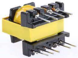
2.2 FLYBACK TRANSFORMER
A unique reasonably Electrical device may be aflybacktransformer (FBT), conjointly noted as a line outputTransformer(LOPT),asshowninFig-2 Ithadbeen ab initio meant to provide comparatively high frequency, highvoltageserrationsignals. It’swideutilizedinswitchedmode power offer for each low voltage (below 3 KV) and highvoltage(over10KV)providesinmodernapplication.
It are usually used as charging unit for Impulse generators,Particleaccelerators.
Medicalapplications(X-Ray).
International Research Journal of Engineering and Technology (IRJET) e-ISSN:2395-0056
Volume: 09 Issue: 11 | Nov 2022 www.irjet.net p-ISSN:2395-0072
switchedcurrentsatmuchhigherfrequenciesintherangeof 15 kHz to 50 kHz, in contrast to a power (or "mains") transformer,whichutilisesanalternatingcurrentof50or60 hertz.
2.3 COCKCROFT WALTON GENERATOR
Fig -2:FLYBACKTRANSFORMER
Theprimarywindingoftheflybackelectricaldevice isdrivenbyaswitchfromaDCoffer(usuallyatransistor). Oncethe switch is switched on, the primary inductance causesthepresenttomakeupinanexceedinglyramp.AN integraldiodeconnectedserialwiththesecondaryprevents the formation of secondary current that may eventually opposetheprimarycurrentramp.
Whentheswitchisturnedoff,thecurrentwithinthe primaryfallstozero.Theenergykeepwithinthecoreisfree tothesecondarybecausethefieldwithinthecorecollapses. Thevoltageamongtheoutputwindingrisesterriblyquickly (usually but a microsecond) till it's restricted by the load conditions. Once the voltage reaches such level on enable secondarycurrent,thechargeflowisamongtheshapeofa downhillramp
The cycle will then be continual. If the secondary currentisallowedtodischargefullytozero(noenergykeep amongthecore),thenit'saforementionedthattheelectrical device works in discontinuous mode (DCM).Oncesome energyissometimeskeepwithinthecore(andthepresent waveformslookquadrangleinsteadoftriangular),then (this isusually)oftencontinuousmode(CCM).Thisnomenclature is utilized particularly in power offer transformers.
Theprimaryiswoundfirstaroundaprimarysolid solution rod, then the secondary is wound round the primary.Thisarrangementminimizestheruninductanceof the primary. Finally, a primary solid solution frame is wrappedaroundtheprimary/secondaryassembly,closing themagneticfluxlines.Betweentherodandthustheframe is AN air gap, that will increase the reluctance. The secondaryiswoundlayerbylayerwithenamelledwire,and Mylar film between the layers.Throughoutthis manner componentsofthewirewithhighervoltagebetweenthem haveadditionalnonconductormaterialbetweenthem.
The operation of CRT-display equipment, such as television sets and CRT computer displays, uses a flyback transformer. Depending on the gadget, voltage and frequencycanbothvarywidely.Withahorizontalscanrate of 15.734 kHz for NTSC devices and 15.625 kHz for PAL devices,forinstance,alargecolourTVCRTmayneed20to 50 kV. A flyback transformer normally operates with
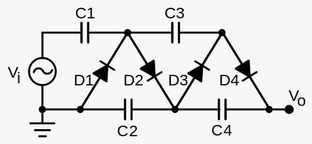
ByconvertingACorpulsingDCelectricalpower,the CWgeneratorisavoltagemultiplierthatincreasesthelevel ofDCvoltagefromlowtohigh.Itcomprisesofacapacitor anddiodevoltagemultiplierladdernetworktogeneratehigh voltages.Thismethod,incontrasttotransformers,doesnot necessitateasubstantialcore,insulation,orpotting.These voltage multipliers can step up very low voltages to extremelyhighvaluesusingonlycapacitorsanddiodes,and they are significantly lighter and less expensive than transformers.Thefundamentaladvantageofsuchcircuitsis that the voltage across each stage of the cascade is only doublethepeakinputvoltageofahalf-waverectifier.This voltage is three times the input voltage in a full-wave rectifier.Itbenefitsfromneedingcomparativelyinexpensive componentsandbeingsimpletoinsulate.Additionally,like withamultitappedtransformer,theoutputfromanystage canbetapped.
Fig -3:CLASSICCOCKCROFTWALTONVOLTAGE MULTIPLIERCIRCUIT
3. DESIGN OF COCKCROFT WALTON VOLTAGE MULTIPLIER
3.1 DESIGN CRITERIA
1.Capacitor selection: -
The frequency of the input signal is directly proportional to the size of the capacitors employed in the multipliercircuit.Thetypeofmultipliercircuitdetermines thecapacitor'svoltagerating.Themaximumvoltagethatthe capacitorcanwithstand dependsonhowmanystagesare beingemployed.Asageneralguideline,chooseacapacitor whosevoltageratingisroughlytwiceashighastheactual peakappliedvoltage.
%Reg=(ΔV/2nVmax)*100
For5%Reg.atVmax=(√3)*2.2kV,n=3
ΔV=(5*2*3*(√3)*2.2)/100
International Research Journal of Engineering and Technology (IRJET) e-ISSN:2395-0056
Volume: 09 Issue: 11 | Nov 2022 www.irjet.net p-ISSN:2395-0072
ΔV=1.14KV
ΔV=(1/fC)*{(2/3)m3+(n2/2)–(n/6)}
Therefore,
C=(1/fΔV)*{(2/3)m3+(n2/2)–(n/6)}
AtΔV=1.14KV,f=10KHz,n=3
C=[1/(10*103*1.14*103)]*{(2/3)*33+(32/2)–(3/6)}
C=1.9uF
C≈2uF
3.2 DIODE SELECTION: -
3.2.1
Repetitive peak reverse voltage: -
The repeated peak inverse voltage is the maximum instantaneousvalueofthereversevoltageacrossthediode. Asaresultofthedevice'sabilitytoconductenoughleakage current,appliedreversevoltageabovethismaximumvalue can cause circuit malfunction and even irreparable component damage. Conversely, applied reverse voltage belowthismaximumvaluewillonlycauseminimalleakage current to flow through the device. In a multiplier circuit, eachdiodedetectsareversevoltageof2Em.Asaresult,the deviceneedstohaveareversevoltage(VRRM)valueofat least2Em.
3.2.2
Frequency of input signal: -
Whenselectingtherectifierdiode,thefrequencyof theinputsignaltothemultipliercircuitmustbetakeninto account.Thegadgetofchoicemustbeabletoflipfasterthan symmetricinputsignals'riseandfalltimings.Ifthereverse recovery time is too long, the device's effectiveness and controlwillsuffer.Intheworstsituation,prolongeddevice heating will result from slow recovery times. And in this case, the equipment will suffer permanent damage. The reverse recovery time is significantly influenced by the circuit and the measuring condition. Backward recovery Timespecificationsshould onlybe utilised for qualitative, notquantitative,purposesbecausetheconditionsgivenfor themeasurementrarelymatchthoseseeninactualreal-life circuitfunctioning.
When utilising a multiplier circuit, a higher input frequency is achievable due to the lower current flow. A spike in current flow has been the opposite outcome. The networkloadonthemultipliermustbetotallycurrent-free.
3.3.3 Peak forward surge current (Ifsm): -
A peak forward surge current rating is given for mostrectifierdiodes.Whenthedevice'sratedloadcurrentis added,thisratingisthehighestpeakvalueofasinglehalf
sine wave that can be produced without damaging the rectifier.Thisratingtakesrelevancewhentheconsiderable capacitanceassociatedtomultipliernetworksistakeninto account.
Ann-stagevoltagemultipliercircuitSurgecurrents mayappearinrectifiercircuitsasaresultofthe effectsof capacitiveloading.Duetothesignificantstep-upturnratio between the primary and secondary in most high voltage transformers, the first multiplier capacitor C1 (on the secondary side) is reflected as a much bigger capacitance into the primary. The following is a general formula to calculatethis:
C'1=NC1,
Where,C1=firstmultipliercircuitcapacitance
C'1=Referredcapacitanceonprimaryside
K= turnsratioofHVtransformerN2/N1
Asthecircuitturnson,asignificantamountofcurrentwill be produced in the primary side, charging the effective capacitance. A significant surge current may flow through the secondary side rectifiers during the initial capacitor charging during turn-on. The installation of a series resistanceRscangreatlyreduceboththesecurrentsurges andthoseinthecorecircuitry.
Rs=Vpeak/Ifsm.
If, maximum secondary voltage, Vrms = 240 volts, then Vpeak=1.414×240V.
Rs=1.414×240/16=21.21Ohm
Ifsm=Forwardsurgecurrentratingofdiode=16Amp.
3.3.4 Forward current (I0): -
As was said before, in an ideal multiplier circuit, the load won'tdrawanycurrent.Idealhighcurrentflowacrossthe rectifierwhilethecapacitorischarging.UseHT/MVcables withequipmentthatcanonlywithstand100mAofcurrent. Utilizing microamperes is a possibility. It is important to understand the connection between forward current and forwardsurgecurrentrating.
Given that both are dependent on the silicon chip region. High forward current I0 rated devices will also have high surgecurrentI0rateddevices,andviceversa.
3.3.5 Forward voltage (Vf): -
The overall performance of multiplier networks is essentiallyunaffectedinpracticebytheforwardvoltageloss Vf of the rectifier. As an example, let's say that when measuredat 100mA ofcurrent,the rectifier diodeshada forward drop of 2.0 volts. A half wave doubler multiplier with an 8 kV output will lose 0.05% (22/8 kV) of its
International Research Journal of Engineering and Technology (IRJET) e-ISSN:2395-0056
Volume: 09 Issue: 11 | Nov 2022 www.irjet.net p-ISSN:2395-0072
efficiencybecauseofforwardvoltagedrop.Thecalculation aboveisfoundedonaruleofthumbthat
Voltage drop is equal to the number of stages * Vf / the outputvoltageinkV.
4. SIMULATION MODEL & RESULT
4.1 INTRODUCTION TO NI MULTISIM SOFTWARE
MULTISIM 14.2
TheNIMultisim14.2(formerlyMultiSIM)electronic schematiccaptureandsimulationsoftwareispartofasetof circuitdesigntools,coupledwiththeNIUltiboard.Multisim isoneofthefewcircuitdesignsoftwareprogrammesthat continuestousetheoriginalBerkeleySPICE-basedsoftware simulation. Multisim was initially created by Electronics Workbench Group, a company that is now a division of National Instruments. In addition to microcontroller simulation,Multisimprovidesintegratedimportandexport featuresforthesuite'sprintedcircuitboardlayoutsoftware, NIUltiboard(formerlyknownasMultiMCU).
4.1.1 SIMULATION MODEL:-
Fig -5:SimulationModelofClassicCockcroftWalton VoltageMultiplier
Thefigure5isthesimulationmodeloftheCockcroft Waltonmultipliercircuit.Itconsistsofamultipliercircuitof aladdercircuitwhichispoweredby230Vat50Hz
4.2 RESULTS:-
The results in this project were based on comparison between the ZVS-based CWG and the classic CWG.Theparametersforconsiderationwerethetransient responseandtheripplecontentofthesystemsateachstage.
4.2.1
TRANSIENT RESPONSE :-
TheTransientResponseforthe3stagesintheZVS circuit based Cockcroft Walton voltage multiplier and a classicCockcroftWaltonvoltagemultiplieraregivenbelow
Fig-4:SimulationModelofZVScircuit-basedCockcroft WaltonVoltageMultiplier
The Fig 4 illustrates the simulation model of ZVS circuit-basedCockcroftWaltonVoltageMultiplier Thegiven model consists of ZVS circuit powered by 12V DC power source,feedingouthighfrequencyACtotheprimaryofthe flybacktransformer,thesecondaryofwhichgivesoutputof highvoltageACwhichis thenfed totheCockcroft Walton multiplierCircuit
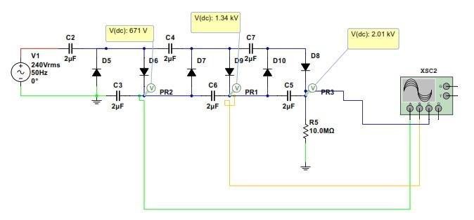

Fig-6: TransientResponseofZVScircuit-basedCockcroft WaltonVoltageMultiplier
The Fig-6 shows the Transient response for the model showninFig-4.TheGreenlineshowsthetransient responseforthe1ststage.TheRedlineshowsthetransient response for the 2nd stage and the blue line shows the transientresponseforthe3rdstage

International Research Journal of Engineering and Technology (IRJET) e-ISSN:2395-0056
Volume: 09 Issue: 11 | Nov 2022 www.irjet.net p-ISSN:2395-0072
Fig-7:-TransientResponseClassicCockcroftWalton VoltageMultiplier
The Fig-7 shows the Transient response for the modelshowninFig-5.ThegreenLineshowsthetransient responseforthe1ststage.TheRedlineshowsthetransient response for the 2nd stage and the blue line shows the transientresponseforthe3rdstage.
4.2.2 RIPPLE VOLTAGE: -
TheRipplevoltages andvoltagedrop forall the3 stagesinboththecircuitshavebeenrecordedandcompared as under for ZVS circuit based Cockcroft Walton voltage multiplierandaclassicCockcroftWaltonvoltagemultiplier fordifferentfrequenciesof5KHzand10KHz
Fig-8 RipplevoltageZVScircuit-basedCockcroftWalton VoltageMultiplier–Stage2
TheFig-8showstheRipplevoltageforthe2ndstage whichisfoundouttobe0.3VforaPeakvoltageof11.5KV.
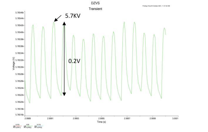
Fig-7 RipplevoltageZVScircuit-basedCockcroftWalton VoltageMultiplier–Stage1
TheFig-7showstheRipplevoltageforthe1ststage whichisfoundouttobe0.2VforaPeakvoltageof5.7KV
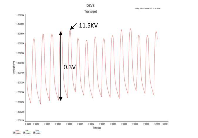
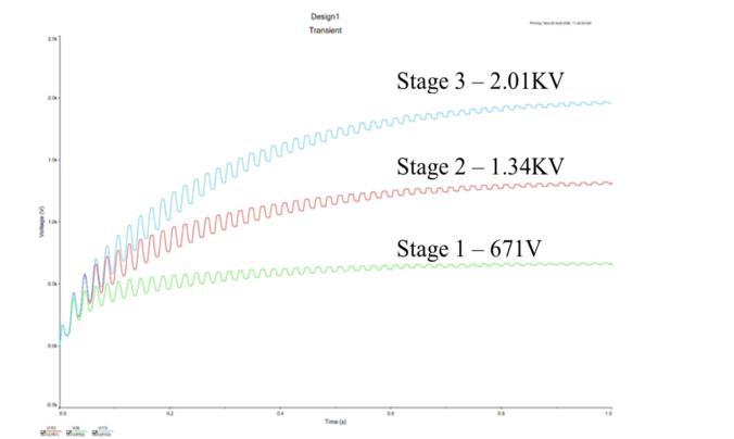
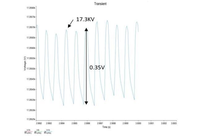
Fig-9 RipplevoltageZVScircuit-basedCockcroftWalton VoltageMultiplier–Stage3
TheFig-9showstheRipplevoltageforthe3rdstage whichisfoundouttobe0.35VforaPeakvoltageof17.3KV
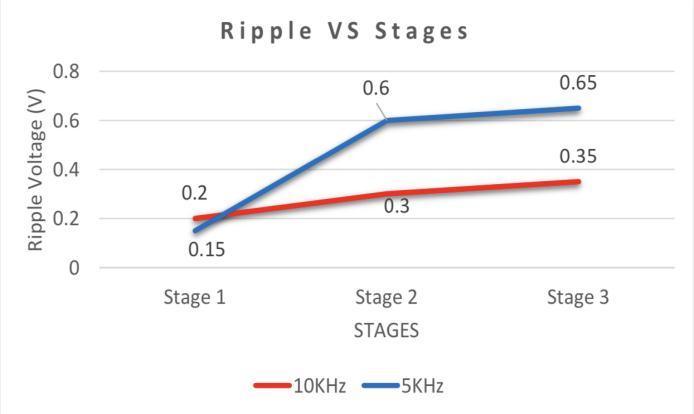
Fig-10 RippleVoltagev/sStage
International Research Journal of Engineering and Technology (IRJET) e-ISSN:2395-0056
Volume: 09 Issue: 11 | Nov 2022 www.irjet.net p-ISSN:2395-0072
TheFig-10showstheRipplevoltagevs stagesfor the3stagesforfrequenciesof5KHzand10Khz.
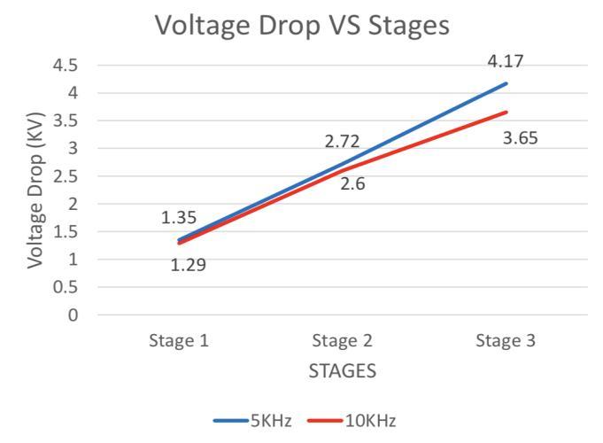
Fig-11 VoltageDropv/sStage
TheFig-11showstheVoltageDropvsstagesforthe 3stagesforfrequenciesof5KHzand10Khz.
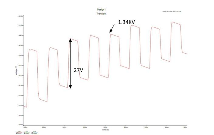
Fig-13 RipplevoltageClassicCockcroftWaltonVoltage Multiplier–Stage2
The Fig-13 shows the Ripple voltage for the 2nd stagewhichisfoundouttobe27VforaPeakvoltageof1.34 KV
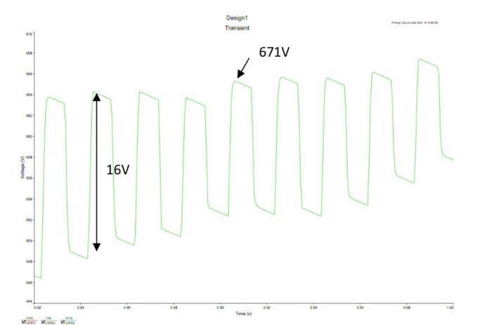
Fig-12 RipplevoltageClassicCockcroftWaltonVoltage Multiplier–Stage1
TheFig-12showstheRipplevoltageforthe1ststage whichisfoundouttobe16VforaPeakvoltageof671V.
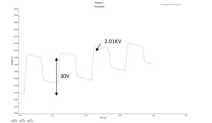
Fig-14 RipplevoltageClassicCockcroftWaltonVoltage Multiplier–Stage3
The Fig-14 shows the Ripple voltage for the 3rd stagewhichisfoundouttobe30VforaPeakvoltageof5.7 KV
4.3 ANALYSIS OF RESULT
From the Fig-6 & Fig-7 it is observed that as compared to the classic model of Cockcroft Walton Generator the modified version of Cockcroft Walton generator driven by ZVS circuit has shown better performanceintermsofripplevoltageandoutputvoltages.
The ripple voltages of classic model are comparativelyhigherascomparedtothemodifiedversion. ForStage1,theripplevoltageforclassicmodelisfoundout tobe16V,whereasinmodifiedversionitisfoundouttobe 0.2V.Similarly,forthe2ndand3rdstagethevalueofripple voltagesforclassicmodelandourmodifiedmodel27Vand 0.3V,30Vand0.35Vrespectively.
International Research Journal of Engineering and Technology (IRJET) e-ISSN:2395-0056
Volume: 09 Issue: 11 | Nov 2022 www.irjet.net p-ISSN:2395-0072
Fig-10 Ripple Voltage v/s Stage, is the graphical analysis of the ripple voltage of the output the stage at variousfrequenciescorrespondingtothestagenumber.It canbeobservedthatathigherfrequencytherippleislower as compared to the lower frequency operation. For the 10KHzfrequencyofoperation,theripplevoltageobserved for the stage 1, stage 2, stage 3 are 0.2V, 0.3V and 0.35V respectively.Similarly,theripplevoltagefor5KHzfrequency ofoperationforstage1,2and3arefoundouttobe0.15V, 0.6Vand0.65V.
Fig-11VoltageDropv/sStage,showsthegraphical analysis of the voltage drop of the stages of multiplier correspondingtothestagenumberfordifferentfrequencyof operation.Theanalysisshowsthatathigherfrequency,the voltagedropis foundout to be lessascompared tolower frequency. The 10KHz frequency of operation shows the voltagedropforthestage1,stage2andstage3as1.29KV, 2.6KV and 3.65KV. Similarly for the 5KHz frequency of operation,thecorrespondingvalueofvoltagedropforstage 1,2and3are1.35KV,2.72KVand4.17KV
CONCLUSIONS
Years after its creation, the Cockcroft-Walton voltage multiplier is still in use and unrivalled in a wide rangeofhighvoltageandactodcconversionapplications Thedesignisacombinationofthreeseparatesystems,aZVS circuitthatsupplieshighfrequencyACpoweratresonance,a step-up transformer to increase voltage and voltage multiplier(CWgenerator)toconvertmediumvoltageACto highvoltageDC.Theproposedmodelisexpectedtoimprove theperformanceoftheCWgeneratorincomparisontothe classical model of CW generator. The simulations of the proposedmodelsarecarriedoutusingMultisimsoftware. Throughthissimulation,thecircuitistested.Theresultsof thesimulationarethoroughlyanalysedandtheperformance parametersaremeasured.Thesimulationresultsarefound out to show a considerable level of improvement in the performance of the generator circuit. This kind of high voltageDCpowersupplytestsetisofsimpletocontrol,low cost, portable due to its light weight, robust and high reliability. Without changing the input voltage, different stagescanproduceoutputsofvaryinghighvoltageDC.This developedequipmentwillbeveryusefulforfieldtestingof HVcablesofdifferentvoltagegrade,asaprimeDCsourcefor VLFandchargingunitofimpulsegenerators.
Thehardwaredesigningandimplementationofthe prototypebasedontheproposedmodelistobedone.Itis expected to be show high performance and to be cost effective.Theactualprototypeistobetestedandtheresults aretobecomparedwiththosefoundinthesimulation.Since, size of the complete high voltage circuit is small and the developed system is cost effective, therefore it is User friendlyaswell as constructionwisethiscircuitis easyto implementandisalsoreliable.
REFERENCES
[
1]VipulV.Nandedkar,NigrodhB.Narnaware,“Designand Implementation of a Cockcroft-Walton Voltage Multiplier Circuit”,2017IJEDR|Volume5,Issue2|ISSN:2321-9939.
[
2] N. Mariun, D. Ismail, K. Anayet, N.Khan and M. Amran, “Simulation, Design and Construction of High Voltage DC Power Supply at 15 kV Output using Voltage Multiplier Circuits”, American Journal of Applied Sciences 3 (12) : 2178-2183,2006.
[
3]WagnerL.AraujoandTarcisioP.R.Campos,“Designofa HighDCVoltageGeneratorandD-TusorbasedonParticle Accelerator”,INAC2011,BeloHorizonte,MG,Brazil.
[
4]NaiduMS,KamarajuV(2004).HighVoltageEngineering. ThirdEdn.McGraw-HillCompanyLtd.
[
5] Kuffel E, Zaengl WS, Kuffel J (2000). High Voltage Engineering fundamental. Second edition, published by Butterworth,Oxford.
[6]CockcroftWaltonvoltagemultiplierhttps://en.wikipedia.org/wiki/Cockcroft%E2%80%93Walto n_generator
[7]FlybackTransformer–https://en.wikipedia.org/wiki/Flyback_transformer
[8]NIMultisim–https://en.wikipedia.org/wiki/NI_Multisim