2395-0056
Volume: 09 Issue: 10 | Oct 2022 www.irjet.net p-ISSN:2395-0072

2395-0056
Volume: 09 Issue: 10 | Oct 2022 www.irjet.net p-ISSN:2395-0072
1PG Student, Structural Engineering, Bapuji Institute of Engineering Technology, Davangere, Karnataka, India. 2Assistant Professor, Dept. of Civil Engineering, Bapuji Institute of Engineering Technology, Davangere, Karnataka, India. ***
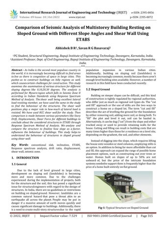
Abstract - As India is the second most populous country in the world, it is increasingly becoming difficult to find areas to live as there is congestion of space in large cities. This pushes us to construct buildings on hilly regions as well, which causescertain challenges for construction. This study examines the examination of various structure for different sloping degrees like 0,10,20,30 degrees. The analysis is performed for Mysoreregion which falls in Seismic Zone II according to Indian Standards using Response Spectrum Method of Analysis. Theshear wall being excellent lateral load resisting member, we have used the same in the study to find the behaviour of the structures. The shear wall positions play a major role in howmuch of lateral load is resisted. We have used RCC shear wallfor the study. Then comparison is made between various parameters like Story Drift, Displacements, Shear Force for different buildings to conclude about the considered structuresin ETABS through Response Spectrum Method of Analysis. We analyse and compare the structure to finalize how slope as a factor, influences the behaviour of buildings. This study helps to understand the behaviour of structures in sloped ground using shear wall.
Key Words: conventional slab, inclination, ETABS, Response spectrum analysis, drift ratio, displacement, shearwall,seismiczone.
Due to the lack of level ground in large cities, development on sloping soil (landslides) is becoming more and more common. Due to the challenges experienced during the implementation of projects, both forthe structureand the soil, this has posed a significant issueforstructuralengineerswithregardtothedesignof structures.InIndia, therearenoguidelinesorrestrictions on building on slopedground. However, landslides are a common natural hazard that pose a threat akin to an earthquake all across the planet.People may be put in danger if a massive amount of earth moves quickly and causessignificantdamagetobuildings.Additionally,there isaneedtocreatemulti-storystructuresdue to the rapid
population expansion in various Indian cities. Additionally, building on sloping soil (landslides) is becomingincreasinglycommon,mostlybecausetherearen't enoughlevelbuildingsitesavailable.However,anumberof researchinthisfieldhavebeenconductedrecently.
Building on steeper slopes canbe difficult, and this kind ofconstructionistightlyregulatedbyregionalauthorities, whodifferjustasmuchasregional soiltypesdo.The"cut and fill" approach or the use of stilts are the two ways to construct a home on a sloped lot. The term "cut and fill" describestheactoflevellingthegroundforthefoundation byeitherremovingsoil,addingmoresoil,ordoingboth.To "fill" the plot and level it out, soil can be hauled in. Alternatively,itcanbedug("cut")fromtheslopeandeither trucked away or used to provide retaining walls for the house.Cuttingandfillingcanresultinbuildingcoststhatare manytimeshigherthanthoseforaresidenceonalevelsite, dependingonthegradient,thesoil,andotherelements.
Insteadofdiggingintotheslope,whichrequireslifting thehouseontowoodenorsteelcolumns,employingstiltsis anoption.Inadditiontobeingfarmoreaffordablethancut andfill,thisapproachcanexpandtherangeofpossiblehome placement options, such as constructing out over trees or water. Homes built on slopes of up to 50% are not unheard of, but the price of the intricate foundation systemsneededtosupportthemisfrequentlyhigherthanthe priceofahomebuiltentirelyonflatground.
International Research Journal of Engineering and Technology (IRJET) e-ISSN:2395-0056
Volume: 09 Issue: 10 | Oct 2022 www.irjet.net p-ISSN:2395-0072
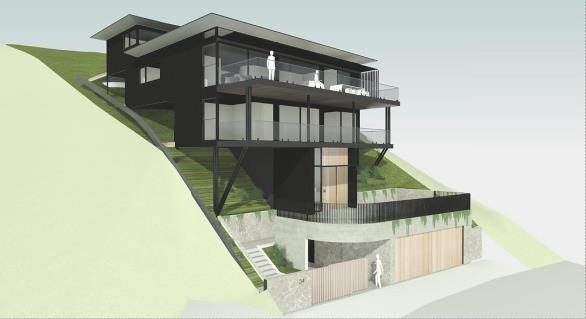
Shear walls play a crucial role in huge, high-rise, or structures located in seismically active or windy regions. In most cases, concrete or masonry are used to build shear walls. Steel braced frames, which can be very successful at resolving lateral forces but may be more expensive,canalsoresist shear forces. Shear walls can be put in place around the outside of buildings, or they can form a shear core, which is a group of shear walls that is usually located in the middleof a building and encloses a stairway or lift shaft. Because the shear wall functions as one element, lateral pressures oftencause rotating forces thatproducecompressionforcesatone cornerandtension forces at the opposite. This "couple" reverses when the lateralforceisappliedfromtheopposingdirection,soboth sides of the shear wall must be able to handle both sorts offorces.
The shear wall's shape and plan position have a significant impact on how the structure behaves. The centreofeachsideofthebuildingistheideallocationfor theshearwallsfromastructuralstandpoint.Butbecauseit limitshowthe space may be used, this is rarely a viable arrangement,thustheyareplacedattheends.
A scientific method for determining the structural reaction to dynamic vibration events is called response spectrum analysis. It is first necessary to determine the system's response spectrum in order to carry out the response spectrum analysis. For linear single degree offreedom system oscillators, the response spectrum plot shows the maximum response to the natural frequency (or natural period) applied to the specified excitation, which may be the maximum displacement, maximum velocity,maximum acceleration, oranyotherparameterofinterest.Aresponsespectrumis a function of frequency or period, showing the peak response of a simple harmonic oscillatorthatissubjected toatransientevent.Theresponsespectrumisafunctionof the natural frequency of the oscillator and of its damping. Thus, it is not a direct representation of the frequency content of the excitation (as in a Fourier transform), but rather of the effect that the signal has on a postulated systemwithasingledegreeoffreedom(SDOF).

Based on historical earthquake activity, India is classifiedinto4zones.WithzoneIIhavingthelowestriskof seismic activity or earthquakes and zone V having the highestlikelihood,zonefactorsaredeterminedbasedonthe zones.Thedesignseismicforcesarecalculatedusingzone factors. The zones aidin implementing the IScode books tobuild the structure in the most useful and economical manner.
1. The study aims to find the behaviour of different structures among the considered buildings with differentslopessuchas0o,10o,20o,30o
2. Loadslikedeadloads,liveloads,windloads,earthquake loadsareappliedontotheslopedstructuresinETABS softwaretool.
3. Then various load combinations are added. A zero sloped structural frame with shear wall is modelled and then analysed, thenothermodelswithvarious sloped degreesareanalysedandtheirresultsarecomparedto finallyconcludethebestbuilding.
International Research Journal of Engineering and Technology (IRJET) e-ISSN:2395-0056
Volume: 09 Issue: 10 | Oct 2022 www.irjet.net p-ISSN:2395-0072
4. This involves comparison of various parameters such as StoryDrift,Displacements,Storyshear,etc.
5. Weanalyseandcomparethestructuretofinalizehow slopeasafactor,influencesthebehaviourofbuildings.
1. A model with no slope is first modelled in ETABS softwareandcheckedforitsbehaviourusingResponse SpectrumMethodofAnalysis.
2. Loadssuchasdeadloads,liveloads,seismicloadsare considered for the analysis of sloped and non-sloped RCCstructureusingtheETABSsoftware.
3. Next few more RCC Structures with various sloping degrees(0o,10o,20o,30o)aremodelledtochecktheir behaviourinResponseSpectrumMethodofAnalysis.
4. Then check how the different structural systems behaves better, based on the output results from the ETABSsoftwaretool.
5. Thencomparisonismadebetweenvariousparameters likeStoryDrift,Displacements,Deflections,fordifferent buildings to finalize the better one out of all the consideredstructuresbothinETABSthroughResponse SpectrumMethodofAnalysis.
6. Onthebasisofobtainedresults,conclusioncanbemade about how one model with certain sloping compares withotherslopedbuildings.
Table -1: ProjectDetails
300x600mm 14 Shearwallthickness 225mm 15 Beamsize 225x300mm & 300x600mm 16 Slabthickness 150mm 17 ConcreteDensity 25kN/m3 18 SolidBrickDensity 20kN/m3 19 MortarDensity 20.4kN/m3 20 EarthquakeLoad As per IS:18932016
Soiltype II, Medium (as per IS:1893-2016)
Dampingratio 5% 23 Responsereductionfactor 5
Case-2 slope
RCCstructurewith0degreeslope Case-1 RCC structure with 10 degree RCC structure with 20 degree slope Case-3 RCC structure with 30 degree slope Case-4
International Research Journal of Engineering and Technology (IRJET) e-ISSN:2395-0056
Volume: 09 Issue: 10 | Oct 2022 www.irjet.net p-ISSN:2395-0072
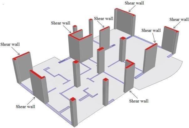
Fig -4:ArchitecturalPlanoftheStructureforalldifferent slopedgrounds
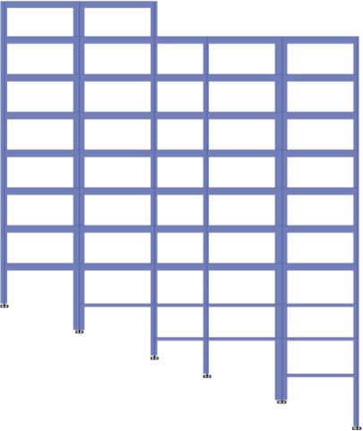
Fig -7:Structurewith20degreeslope
Fig -5:Structurewith0degreeslope
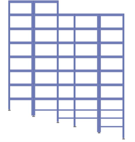
Fig -8:Structurewith30degreeslope

The maximum valuesofstoreydisplacementinboth X & Y directions for all 4 cases is shown below. Whencompared with the rest of the cases it is found that theCase- 1 has the minimum displacement values. 3.017745mm & 4.431059mm in X & Y – Directions are thevaluesofCase-1.
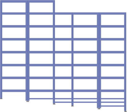
Fig -6:Structurewith10degreeslope
International Research Journal of Engineering and Technology (IRJET) e-ISSN:2395-0056
Volume: 09 Issue: 10 | Oct 2022 www.irjet.net p-ISSN:2395-0072
Table -3: Max. Storey Displacement Values in X & Y –
Direction
MAXIMIUM DISPLACEMENT VALUES (mm)
Case/Direction X-Direction Y-Direction
CASE-1 3.017745 4.431059
CASE-2 3.758256 4.782361 CASE-3 4.123775 4.964847 CASE-4 5.518464 5.77299
Fig -10:Max.StoreyDriftValuesinX&Y–Direction
Themaximumvaluesofstoreyshearin bothX & Y directions for all 4 cases is shown below. When compared with the rest of the cases it is found that the Case-1 has the minimum drift value of 0.000171 in X DirectionandCase-2hasminimumdriftvalueof0.000231 inYDirection.
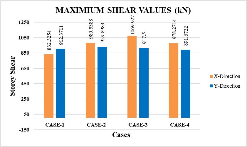
Table -5: Max.ShearinX&Y–Direction
VALUES OF MAXIMIUM SHEAR (kN)
Fig -9: Max.StoreyDisplacementValuesinX&Y –Direction
4.2 Storey Drift
The maximum values of storey drift in both X & Y directions for all 4 cases isshown below. When compared withtherestofthecasesitisfoundthattheCase-1hasthe minimumdriftvalueof0.000171inXDirectionandCase-2 hasminimumdriftvalueof0.000231inYDirection.
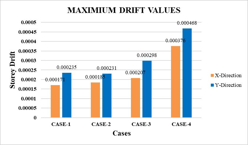
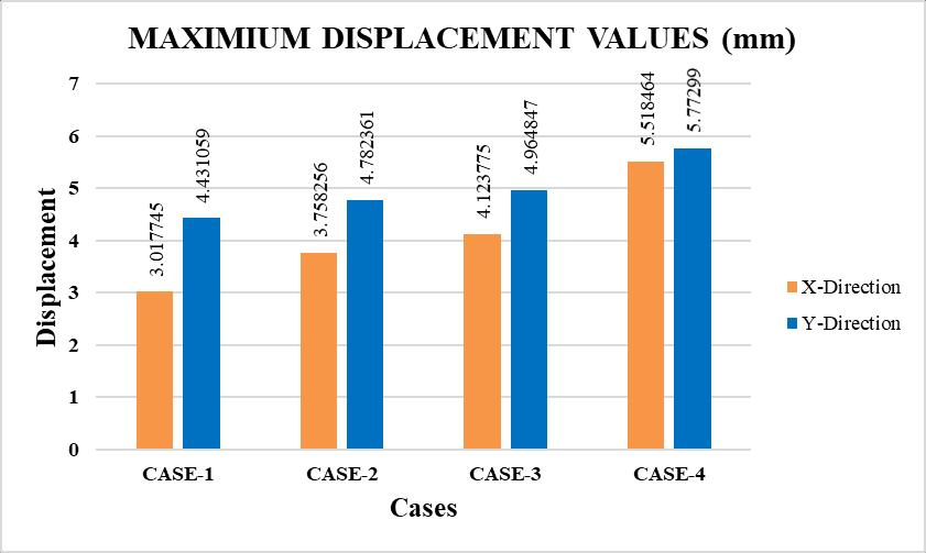
Table -4: Max.StoreyDriftinX&Y–Direction
VALUES OF MAXIMIUM DRIFT RATIO
Case/Direction X-Direction Y-Direction
CASE-1 0.000171 0.000235
CASE-2 0.000185 0.000231
CASE-3 0.000207 0.000298
CASE-4 0.000376 0.000468
Case/Direction X-Direction Y-Direction
CASE-1 832.3254 902.3701 CASE-2 980.5388 929.8983 CASE-3 1069.927 917.5 CASE-4 978.2714 891.6722
Fig -11:Max.ShearinX&Y–Direction
International Research Journal of Engineering and Technology (IRJET) e-ISSN:2395-0056
Volume: 09 Issue: 10 | Oct 2022 www.irjet.net p-ISSN:2395-0072
1. Themaximumstoreydisplacementinxandydirection inCase1is3.017745mmand4.431059mmrespectively, whereastheminimumstoreydisplacementinxandy directionis0.068394mmand0.078624mmrespectively.
2. Themaximumstoreydisplacementinxandydirection inCase2is3.758256mmand4.782361mmrespectively, whereastheminimumstoreydisplacementinxandy directionis0.459103mmand0.324313mmrespectively.
3. Themaximumstoreydisplacementinxandydirection inCase3is4.123775mmand4.964847mmrespectively, whereastheminimumstoreydisplacementinxandy direction is 0.982931mm and 0.606763mm respectively.
4. The maximum storey displacement in x and y directionin Case 4 is 5.518464mm and 5.77299mm respectively, whereas the minimum storey displacement in x and y direction is 1.38021mm and 0.924429mm respectively.
5. ThemaximumstoreydriftinxandydirectioninCase 1is0.000106and0.000189respectively,whereasthe minimumstoreydriftinxandydirectionis4.49E-05 and5.16E-05 respectively.
6. ThemaximumstoreydriftinxandydirectioninCase 2is0.000110and0.000195respectively,whereasthe minimumstoreydriftinxandydirectionis0.000127 and0.000177respectively.
7. ThemaximumstoreydriftinxandydirectioninCase 3is0.000121and0.000196respectively,whereasthe minimumstoreydriftinxandydirectionis0.000176 and0.000298respectively.
8. ThemaximumstoreydriftinxandydirectioninCase 4is0.000146and0.000204respectively,whereasthe minimumstoreydriftinxandydirectionis0.000376 and0.000468respectively.
9. ThemaximumstoreyshearinxandydirectioninCase1 is 832.3254kN and 902.3701kN in storey 1 respectively,whereas the minimum storey shear in x and y direction is 87.15073kN and 117.3832kN in storey8respectively.
10. ThemaximumstoreyshearinxandydirectioninCase2 is 980.5388kN and 929.8983kN in storey 1 respectively,whereas the minimum storey shear in x and y direction is 96.17316kN and 113.9995kN in storey8respectively.
11. ThemaximumstoreyshearinxandydirectioninCase3 is 1069.927kN and 917.5kN in storey 1 respectively, whereas the minimum storey shear in x and y directionis 103.8764kN and 107.7766kN in storey 8 respectively.
12. ThemaximumstoreyshearinxandydirectioninCase4 is 978.2714kN and 891.6722kN in storey 1 respectively,whereas the minimum storey shear in x and y direction is 99.56052kN and 101.1958kN in storey8respectively.
In the entire study we compared how the structure behaves for different sloping ground types. We had considered 0, 10, 20, 30 degree slopes and analysed the structure using ETABS software by Response Spectrum Method of Analysis for zone II. The comparisons made using the graphs and tables gave a clear insight of how those structuresbehavewithslopeandthefollowingconclusions canbesaidfromobservationoftheresultsobtainedinthe study.
1. ThemaximumvaluesofStoreyDisplacementarefound lesserincase-1whencomparedwithmaximumvalues i.e.,case-4.
2. ThemaximumvaluesofStoreyDriftarefoundlesserin case-1whencomparedwithmaximumvaluesi.e.,case4.
3. ThemaximumvaluesofStoreysheararefoundlesserin case-1 when compared with maximum values i.e., case-4.
4. ThemaximumvaluesofStoreyDisplacementofcase1are found 82.89% and 34.18% lesser in X & Ydirectionswhencomparedwithcase-4.
5. ThemaximumvaluesofStoreyDriftofcase-1arefound 157.53% and 129.41% lesser inX &Y-directions when comparedwithcase-4.
6. Thetopmostheightof thestructurevaluesof Storey Driftofcase-1arefound61.32%and24.33%lesser in X&Y-directionswhencomparedwithcase-4.
7. ThemaximumvaluesofStoreyshearofcase-1arefound 17.53% and 1.25% lesser in X & Y- directions when comparedwithcase-4.
8. From the above compared storey displacement, drift and shears terms, we can say that case-4 has found higher values when compared with other cases i.e., 30oinclinedbasestructure.
International Research Journal of Engineering and Technology (IRJET) e-ISSN:2395-0056
9. The values of storey displacement, drift and shears areincreaseswhenincreasedwithangleofground.
10. The values of X- directions has found higher values comparedwithY-directionsvalues.
Basedon the work carried outin this projectwehad given the above conclusions. The given following are the scopesfortheworkaheadthatcanbecarriedouttostudy othercharacteristicsrelatedtoslopedstructures.
1. The structure can be studied for other seismic zones ofIndiausingsameordifferentslopes.
2. The structure on sloped ground can be studied for theeffectsofwindloads.
3. ThecomparisonofHighrisestructurescanbestudied.
4. The study with bracings, viscous dampers, tuned massdamperscanbefurtherstudied.
5. The effects of blast load on sloped structures can befurtherstudiedfordifferentzones.
6. The structure can compared with different StandardCodes from different countries to check the behaviour.
1. IS 800:2007, “Indian Standard Code of Practice for General Steel Construction”, Bureau of Indian Standards,NewDelhi,India.
2. IS 875 (Part 1) – 1987, “Indian Standard Code of PracticeforDesignLoads(OtherthanEarthquake)for buildings and Structures. Part 1 - Dead Loads – Unit weights of building materials and stored materials”, BureauofIndianStandards,NewDelhi,India.
3. IS 875 (Part 2) – 1987, “Indian Standard Code of PracticeforDesignLoads(OtherthanEarthquake)for buildings and Structures. Part 2 - Imposed Loads –Unit weights of building materials and storedmaterials”, Bureau of Indian Standards, New Delhi,India.
4. IS 875 (Part 3) - 2015 "Design Loads (Other than Earthquake)forBuildingsandStructures” —Codeof Practice Part 3 Wind Loads, Bureau of Indian Standards,NewDelhi,India.
5. IS 875 (Part 5) – 1987, “Indian Standard Code of Practice for Design Loads for buildings and Structures. Part 5 – Load Combinations, Bureau of IndianStandards,NewDelhi,India.
Volume: 09 Issue: 10 | Oct 2022 www.irjet.net p-ISSN:2395-0072 © 2022, IRJET | Impact Factor value: 7.529 | ISO 9001:2008 Certified Journal | Page324
6. IS 1893 (Part 1) - 2016 “Criteria for Earthquake Resistant Design of Structures”, Bureau of Indian Standards,NewDelhi,India.
7. IS : 811-1987 “Specification for Cold formed Light Gauge Structural Steel Sections” Bureau of Indian Standards,NewDelhi,India.
8. AnjeetSinghChauhanandRajivBanerjee(2021)
“Seismic Response Of Irregular Building On Sloping Ground”, International Journal of Advanced Research in Engineering and Technology (IJARET), ISSN Print: 0976-6480,Volume12,Issue5,pp.181-202
9. A. S. Swathi, et al, (2013) “Seismic Performance of Buildings on Sloping Grounds”, International Journal of Innovative Research in Science, Engineering and Technology,ISSN(Online):2319–8753,Vol.4
10. NarayanKalsulkarandSatishRathod(2015)“Seismic Analysis of RCC Building Resting on Sloping Ground with varying Number of Bays and Hill Slopes”, International Journal of Current Engineering and Technology,E-ISSN2277–4106,Vol.5
11. Prasad Ramesh Vaidya (2015) “Seismic Analysis of Building with Shear Wall on Sloping Ground”, International Journal of Civil and Structural Engineering Research, ISSN 2348-7607, Vol. 2, Issue 2,pp(53-60)
12. Rahul Ghosh and Rama Debbarma (2019) “Effect of slopeanglevariationonthestructuresrestingonhilly region considering soil–structure interaction”, International Journal of Advanced Structural Engineering,s40091-019-0219-3
13. R. B. Khadiranaikar and Arif Masali (2014) “Seismic performanceofbuildingsrestingonslopingground−A review”, IOSR Journal of Mechanical and Civil Engineering,ISSN:2278-1684,Volume11,Issue3,PP 12-19
14. SujitKumar,etal(2014)“EffectOfSlopingGroundOn StructuralPerformanceOfRccBuildingUnderSeismic Load”, International Journal Of Science, Engineering AndTechnology,ISSN:2348-4098,Volume2,Issue6