International Research Journal of Engineering and Technology (IRJET)
e-ISSN: 2395-0056
Volume: 08 Issue: 08 | Aug 2021
p-ISSN: 2395-0072
www.irjet.net
An Overview of Structural UML Diagrams Bhavik Bhatt1, Muskaan Nandu2 1Bhavik
Bhatt, Dept. of Information Technology, KJ Somaiya College of Engineering, Maharashtra, India Nandu, Dept. of Information Technology, KJ Somaiya College of Engineering, Maharashtra, India ---------------------------------------------------------------------***---------------------------------------------------------------------2Muskaan
Abstract - UML stands for Unified Modeling Language. UML
is explained by presenting the results of a survey on using some of the popular structural diagrams.
diagrams are used to graphically visualize an abstract model of a system. The paper includes a brief introduction of UML diagrams and explains the two types of UML diagrams Structural UML Diagrams and Behavioral UML Diagrams. This paper is an overview of Structural UML diagrams. We have discussed 5 Structural diagrams namely: Class diagram, Object Diagram, Component Diagram, Deployment diagram and Package Diagram. We have also presented the results of a survey which explains how the Class Diagram is the most important and most used Structural Diagram.
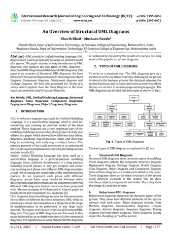
2. TYPES OF UML DIAGRAMS To write in a standard way, The UML diagrams give us a method to write a system's overview, defining all the phases involved in the business process like database schemas, the system functions, and in some cases even an overview of how classes are written in certain programming languages. The UML diagrams are divided into two types as shown in Fig 1.
Key Words: UML, Unified Modeling Language, Structural diagrams, Class Diagrams, Component Diagrams, Deployment Diagrams, Object Diagrams, Diagrams.
1. INTRODUCTION UML in software engineering stands for Unified Modelling Language. It is a specification language which is used for visualizing and creating an abstract model of the final product. These diagrams are a very important part of the modeling and design process step of any project. A study was offered in a paper which showed how different data tables, diagrams, graphical representations, maps and drawings help in visualizing and analyzing a subject better. The primary purpose of the study mentioned is to understand the use of visual inscriptions in science, by providing various analysis results [1]. Mainly, Unified Modeling Language has been used as a specification language or a general-purpose modeling language. Since, software development is a long process including several phases, it may get complex and hence representing each phase with different UML diagrams plays a vital role in easing the complexity of the implementation process. As we represent each phase with different diagrams, certain basic rules should be followed while drawing such diagrams to maintain the consistency between different UML diagrams. Certain rules have been proposed with relevant examples in Mohammad N, Alanzi’s paper to build correct and consistent UML diagrams [2]. UML diagrams have found huge success for documentation of workflow of different business processes. UML helps in providing a visual representation or a blueprint of the steps of implementation to be performed in any large scale projects. This paper provides an overview of Structural UML diagrams. The types of UML diagrams are discussed in this paper followed by an in-depth overview of a few structural diagrams. The significance of using Structural UML diagrams
© 2021, IRJET
|
Impact Factor value: 7.529
Fig -1: Types of UML Diagrams The two types of UML diagram as explained in [3] are: a. Structural UML Diagrams Structural UML diagrams show the static aspect of modeling. These diagrams include: the composite structure diagram, Deployment diagram, Package Diagram, Profile Diagram, Class Diagram, Object Diagram and Component diagram. Some of these diagrams are explained in detail in this paper. These diagrams show us the main structure of the system using different elements of the system like its class, interfaces, objects, components and nodes. Thus, they show the things of a modeled system. b. Behavioural UML diagrams Behavioural diagrams represent the dynamic aspect of the system. They show how different elements of the system interact with each other. These diagrams include: State Machine diagrams, Communication diagrams, Usecase diagrams, Activity diagrams, Sequence diagrams, Timing diagram and Interaction diagrams. These diagrams mainly depict the changing parts of the system
|
ISO 9001:2008 Certified Journal
|
Page 1577