International Research Journal of Engineering and Technology (IRJET)
e-ISSN: 2395-0056
Volume: 08 Issue: 07 | July 2021
p-ISSN: 2395-0072
www.irjet.net
Voltage Controlled Design of a Cycloconverter for Variable Frequency Operation with Harmonics Elimination Technique Pranjit Kumar Roy1 1Assistant
Professor, Dept. of Electrical Engineering, Bengal College of Engineering and Technology, West Bengal, India ---------------------------------------------------------------------***----------------------------------------------------------------------
Abstract – The major findings of this paper are based on
realization of a Cycloconverter which is having an immense importance for the frequency controlled drives and various high frequency applications. The deviation of source voltage is controlled simultaneously with the frequency of the output signal which is maintained effectively under desired limit. The positive and negative sequence of switching signals are applied maintaining mathematical modeling and simulation of the proposed model. It is developed using MATLAB/Simulink software. The Model is simulated with resistive and inductive type of loading which incurs harmonic distortions at the output end. The filtering of the harmonic contents are shown in this paper and which lies under the IEEE specified standard limits. Fast Fourier Transform (FFT) is used as a mathematical tool to analyze the limit of harmonics in MATLAB platform. The synchronized operation of generating pulses after calculating the optimum pulse width and time interval result in successful operation of the proposed Cycloconverter model.
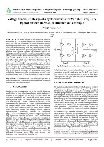
Fig -1: Bridge type configuration of Cycloconverter P1, P2, P3 and P4 are four switches which are operated for the conduction of positive half-cycle and N1, N2, N3 and N4 are four switches for the conduction of negative half-cycle. Pulse-generators are the used to provide necessary firing pulses for each switch.
Key Words: Cycloconverter, Controlled-voltage source, Conduction period, Fast Fourier Transformation, Harmonic elimination, Variable frequency.
2. WORKING OF SIMULATED MODEL
1. INTRODUCTION
The Cycloconverter is operated in two half-cycle i.e. positive half-cycle and negative half-cycle. In positive half-cycle, Thyristors T1, T2, T3 and T4 are under operating condition while the gate pulses are provided from pulse generator 2. In case of negative half-cycle, Thyristors T5, T6, T7 and T7 are in working state while gate pulses are fed from pulse generator 3 after applying certain conduction period [3]. Four switches are used here where switch 3 and switch 4 are in phase opposition for maintaining the sequence of negative halfcycle with logical NOT operator and gate pulses are sent from pulse generator 1. The voltage that is acted as input is controlled continually with respect to the voltage at load end.
Cycloconverter plays a crucial role for the variable frequency applications by controlling its conduction period. Various a.c. appliances are needed to run with variable speed for different household and industrial applications where Cycloconverter meets the required demand efficiently and cost effectively [1]. It converts the constant frequency to the desired variable frequency in a single stage and losses will be comparatively lower compare to the other existing techniques. There are different applications where standard 50Hz frequency cannot be directly utilized whereas Cycloconverter effectively reduces the frequency (e.g. 1/3rd or 1/4th of the rated/supplied frequency) without any significant stresses or losses. The Cycloconverter consists of two bridges. Bridge 1 indicates the operation of positive half cycle as well as bridge 2 indicates the operation of negative half cycle. The signals are generated maintaining the sequence logic and duration of conduction are also controlled. This methodology is implemented on R-L type of load where the input voltage is controlled continuously [2]. The output voltage and current waveforms are verified for different frequency levels. The basic bridge type Cycloconverter circuit is shown in Fig -1.
© 2021, IRJET
|
Impact Factor value: 7.529
The Cycloconverter model is simulated with resistive and inductive type of loading environment. The inductive type loading induces harmonics in the voltage and current at the output side which are beyond the standard limits. The harmonic contents are mitigated using capacitors C1, C2 and internal inductor with controlled voltage utilization. After the implementation of Fast Fourier Transform (FFT), Total Harmonic Distortion (THD) is analyzed and elimination of harmonics in the output parameters are shown [4]. For various industrial drives, variable frequency is an essential parameter [5] which is verified and depicted after successful simulation of the described Cycloconverter. The
|
ISO 9001:2008 Certified Journal
|
Page 4202