International Research Journal of Engineering and Technology (IRJET)
e-ISSN: 2395-0056
Volume: 08 Issue: 07 | July 2021
p-ISSN: 2395-0072
www.irjet.net
Design and Analysis of Space Borne Camera Sachin Padaki1, M.M. M. Patnaik2, A. K. Sharma3 1Student,
M.Tech (Machine Design), K. S. Institute of Technology, Karnataka, India. Professor, , K. S. Institute of Technology, Karnataka, India. 3Indian Space Research Organization (ISRO), Laboratory for Electro-Optics Systems (LEOS), Scientist/Engineer SH, Mechanical Division Head, Karnataka, India. ---------------------------------------------------------------------***---------------------------------------------------------------------2Associate
Abstract -Docking and berthing are two techniques for
the moon with 5m spatial resolution. The swath coverage will be 20km.The weight of the instrument is about 6 kg [5]. Selection of the number of detectors and number of Optics module lenses usage and the material selection for the mission of cameras is purely depend on the function it going to perform in the space and purely a requirement to the space application on the bases of the application mass and size of the of the camera package will be varies. Mast Camera, Mars colour camera and Terrain Mapping Camera are used for the imaging purpose so for. This SBC is mainly used for the docking in India first time [3-5].
making contact of two space vehicles in space environment. Docking specifically refers to capture of free-flying space vehicles by another. Docking camera and navigation systems will make docking and undocking of Space Station and another spacecraft easier and safer. This is the first time INDIA is going to achieve the docking of space craft's. This paper deals with the “Design and Analysis of Space Borne Camera" which has to sustain the launch vibrations and work in stringent space environment. The docking spacecrafts should move towards another spacecraft, using direction, attitude, angles of target vehicle with high precision for this Space Borne Camera (SBC) system being designed. The static and dynamic characterization of the designed camera has been evaluated and simulated using FEA tools. The target identification range of camera is 20m. The several test conditions such as Modal Analysis, Quasi static analysis, Thermostatic Analysis, Random Vibration Analysis and simulation results are adequate. The design is ready to be incorporate in the space mission.
1.1 Working principle
Key Words: Docking, Space borne camera, Berthing, Dynamic characterization. Modal Analysis.
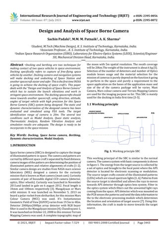
1.INTRODUCTION Fig. 1. Working principle SBC
Space borne camera (SBC) is designed to capture the image of illuminated pattern in space. The camera and pattern are carried by different space craft's separated by fixed distance; camera images of the pattern are determining the position of illuminated pattern and relative alignments of crafts [1-2]. Similar camera design are studies from NASA mars science laboratory (MSL) designed a camera for the curiosity mission that is known as Mast camera (mast cam). Curiosity consists of pair of focusable digital CCD camera (detector, optics, filter wheels). Curiosity was launched in November 2011and landed in gale on 6 august 2012. Focal length is 34mm and 100mm respectively [3]. Mangalyaan or Mars orbit mission: It was launched on November 5, 2013 on board a polar rocket from shriharikot, for this mission Mars Colour Camera (MCC) was used. It’s Instantaneous Geometric Field of View [IGFOV] varies from 19.5m to 4Km. Detector 2000pxx2000px array detector with RGB buyer filter is used in the Mangalyaan mission [4]. Chandrayann-1, It was launched on October 22, 2008 in this mission Terrain Mapping Camera was used. A complete topographic map of © 2021, IRJET
|
Impact Factor value: 7.529
This working principal of the SBC is similar to the normal camera. The camera system with basic components is shown in figure 1. The energy from the target source is collected by a set of optics and brought to the focal point where the APS detector is located for electronic scanning or modulation. The source target crafts consist of the illuminated patterns (LEDs) which are visual spectrum lights [1, 6]. Patterns from the source target is identified and allows the rays to moves towards APS detector through optics lens system. Filter in the optics system which filters out the unwanted light rays coming from the space. APS detector which was mounted on the PCB senses the patterns and send the data information to the to the electronic processing module which determines the location and orientation of target source [7]. Using this information, the craft is made to move towards the target source.
|
ISO 9001:2008 Certified Journal
|
Page 3443