International Research Journal of Engineering and Technology (IRJET)
e-ISSN: 2395-0056
Volume: 08 Issue: 07 | July 2021
p-ISSN: 2395-0072
www.irjet.net
Efficient High Step Up DC-DC Conversion using Fuzzy Logic Control and SEPIC Converter Shobana. D1, Arunthavaraj.A2, Santhosh Kumar.J3, Sujith Naarayan.H4, Nirmal Kumar.S5 1Associate
Professor, Dept. of Electrical & Electronics Engineering, Panimalar Institute of Technology, Chennai, India 2,3,4,5UG Scholar, Dept. of Electrical & Electronics Engineering, Panimalar Institute of Technology, Chennai, India ---------------------------------------------------------------------***----------------------------------------------------------------------
Abstract - Renewables are steadily growing in popularity
components used. The active switched LC network with a high step-up dc-dc converter was chosen because of its high conversion ratio, high reliability, and low voltage stress on the active switches. Various high step-up DC-DC converters have been suggested to address these drawbacks. Furthermore, various techniques and circuits are given to increase the voltage gain and reduce the duty cycle values. Voltage-boosting methods, such as switched LC networks, are among them. To improve the boost ability, a switched inductor(L) technique is used. To increase the voltage gain, a switched capacitor (C) is used. The voltage stress on the semiconductor switches is reduced in these converters, which aids in the selection of MOSFET’s with low static resistance to improve performance by lowering conduction loss. This form of soft switching, on the other hand, helps to remove voltage spikes. As a result, snubber circuits are needed to provide voltage stress safety to the output diodes. When compared to traditional converters, MOSFET switch on losses is also lower.[1]paper gave the idea to develop a DC-DC converter using SEPIC Converter as it is less complex compared to the OVR method(Output Voltage Regulation) used there.[2] helped in implementing the basic DC-DC converter in MATLAB.[3],[4],[5],[6] gave the idea about implementing converter using Fuzzy Logic Control.
and are becoming incredibly valuable in the production and distribution of goods. As a result, a high voltage DC-DC converter with an active SEPIC network along with fuzzy logic control is proposed in this paper. This converter is used to boost the PV panel's output voltage to a higher level. With only one MOSFET, the active LC network is used to increase the voltage gain. Under continuous conduction mode, the high voltage gain is achieved by storing and discharging energy in inductor and capacitor. The current and voltage ripples are reduced. The high voltage gain is accomplished without using a duty cycle ratio that is too high. Key Words: SEPIC Converter, Fuzzy logic, High step-up DC-DC conversion, Photovoltaic, Micro-grids.
1. INTRODUCTION DC microgrids have rapidly become common in a variety of applications. For integrating photovoltaics (PVs) in such, DC microgrids, a variety of current structures are accessible. The most common PV integration topologies are centralized, multi-string, string, module, and sub module integration. Owing to the exploitation of traditional resources, the energy demand of daily life can only be met by renewable resources. Renewable energy sources such as solar panels and fuel cells have low output voltages that must be increased. Traditional boost converters require high-power rating switches, which causes conduction loss and limits the output voltage, even at very high duty cycles. According to the available boost converter's theoretical ideas, when the service cycle hits unification, the static gain would be infinite. High duty cycle values, on the other hand, result in lower voltage gain and performance. As a result, we've opted to use a high-step-up dc-dc converter to increase the output voltage. Coupled inductor and non-coupled inductor are two types of highstep-up DC-DC converters. High voltage gain can be achieved in coupled inductor forms by changing the coupled inductor turns ratio. However, voltage spikes may be caused by the leakage inductance. As a result, the topology's complexity is increased in this case.
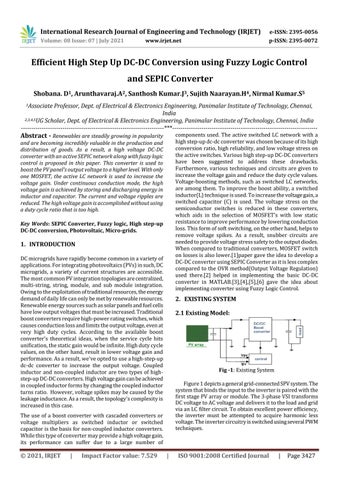
2. EXISTING SYSTEM 2.1 Existing Model:
Fig -1: Existing System Figure 1 depicts a general grid-connected SPV system. The system that binds the input to the inverter is paired with the first stage PV array or module. The 3-phase VSI transforms DC voltage to AC voltage and delivers it to the load and grid via an LC filter circuit. To obtain excellent power efficiency, the inverter must be attempted to acquire harmonic less voltage. The inverter circuitry is switched using several PWM techniques.
The use of a boost converter with cascaded converters or voltage multipliers as switched inductor or switched capacitor is the basis for non-coupled inductor converters. While this type of converter may provide a high voltage gain, its performance can suffer due to a large number of
© 2021, IRJET
|
Impact Factor value: 7.529
|
ISO 9001:2008 Certified Journal
|
Page 3427