International Research Journal of Engineering and Technology (IRJET)
e-ISSN: 2395-0056
Volume: 08 Issue: 07 | July 2021
p-ISSN: 2395-0072
www.irjet.net
DESIGN AND ANALYSIS OF CONNECTING ROD USING COMPOSITE MATERIALS AND ALLOYS Mr. Sumukh. R1, Mr. Sankalp Khobragade2, Mr. Vishwaradya Patil3, Mr. Vishwas K4, Mr. Hemanth Kumar J5 1Mr.
Sumukh .R: Student, Department of Mechanical Engineering, PESIT-BSC, Bengaluru, Karnataka. Mr. Sankalp Khobragade: Student, Dept. of Mechanical Engineering, PESIT-BSC, Bengaluru, Karnataka. 3Mr. Vishwaradya Patil: Student, Department of Mechanical Engineering, PESIT-BSC, Bengaluru, Karnataka. 4Mr. Vishwas K: Student, Department of Mechanical Engineering, PESIT-BSC, Bengaluru, Karnataka. 5Mr. Hemanth Kumar J: Assistant Professor, Dept. of Mechanical Engineering, PESIT-BSC, Bengaluru, Karnataka. ---------------------------------------------------------------------***---------------------------------------------------------------------2Mr.
Abstract - The connecting rod is the intermediate member
under unfavourable conditions. An ideal Connecting Rod should have minimal weight and cost effective, but also should be strong enough to withstand high stresses and high cycle fatigue. In the past years, research based on connecting rod has shifted from materials having uniform composition to many other metal alloys and composite materials for enhancement of performance, strength and stiffness, reduction of weight, wear and corrosion resistance, and also for reducing the thermal expansion. Metal Matrix Composites (MMCs), Aluminum-Silicon Carbide Composite and many metal alloys meets the requirements for applications requiring combined strength, thermal conductivity, and low coefficient of thermal expansion with lower density to reduce the weight of the connecting rod and increase the efficiency of the engine.
between the piston and the Crankshaft. Its primary function is to transmit the push and pull from the piston pin to the crank pin, thus converting the reciprocating motion of the piston into rotary motion of the crank. Most common cases of failure of Connecting Rod are of Tensile Failure, which happens due to high engine speeds, or Casting Defect, which develops due to cyclic load behavior. This project aims to replace the typical convention material used for manufacturing connecting rod like Steel, so as to improve the performance parameters while reducing the overall weight of the component. This study aims on comparing a connecting rod of standard dimensions and made up of convention material like Steel with that made up of composite materials like Aluminum-Beryllium Alloy, Aluminum-Silicon Carbide Composite and Titanium Alloy. The Shape and the Materials have been selected based on the Strength and Stiffness Criteria. The project also performed Static Structural parameters like Von-Mises Stress, Deformation, Factor of safety and Buckling Analysis of standard connecting rod design using FEM on a commercial software ANSYS workbench, to predict structural strength and buckling limit of the model. Key Words: Connecting rod, Aluminum Silicon Carbide composite, Steel, Aluminum Beryllium alloy, Titanium alloy, Strength to weight ratio.
1.INTRODUCTION
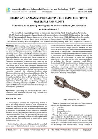
Fig -1: Connecting rod
Connecting Rod converts the reciprocating motion of piston into rotary motion of the crank shaft. It connects the crank and the piston and thus transfer the power for the movement of the vehicle. Since, it converts the linear motion of piston into rotary motion of the crankshaft, it undergoes following kinds of loads and stresses like bending, tension, compression and buckling. The bigger end of the connecting rod connects the crank shaft with the help of crank pin with a plain bearing. The smaller end is connected to piston through piston pin. “
“Based on the shape of the cross section of the connecting rod they are classified mainly into four categories: 1. I - section 2. H - section 3. Rectangular section 4. Circular section“ “Among these cross-sections circular and rectangular cross sections are the most stressed cross sections. Hence these shapes are ruled out of our analysis. The other two sections had less stress concentrations and showed better results. But I-section has better shape factor in bending both due to strength and stiffness effect. Hence I-section is
“Connecting Rod is the part of IC engine that is under high stress most of the time, hence it is more prone to failure
© 2021, IRJET
|
Impact Factor value: 7.529
|
ISO 9001:2008 Certified Journal
|
Page 3125