International Research Journal of Engineering and Technology (IRJET)
e-ISSN: 2395-0056
Volume: 08 Issue: 07 | July 2021
p-ISSN: 2395-0072
www.irjet.net
Vibration Analysis of a Heavy Duty Vehicle King-pin and the Study of its Effects on King-pin Life Miss. Trupti Y. Galat1, Prof. A. M. Shende2 1Trupti
Yogeshwar Galat, Student of M.E. (Mechanical CAD/CAM) 2nd Yr, Jagadambha College of Engineering and Technology, Yavatmal, Maharashtra, India 2Anirudh M.Shende Assitant Professor of Mechanical Engineering Department, Jagadambha College of Engineering and Technology, Yavatmal, Maharashtra, India ---------------------------------------------------------------------***----------------------------------------------------------------------
Abstract - Heavy duty vehicles always undergo to heavy
changing only if the wheel spindle or steering knuckles are bent.
loading and hard impacts while running. It often produces vibrations which are due to the bad road conditions, high engine speed or sudden jerks while running on road. Hence the produced vibrations may impact on the king-pin working and its life. We always measure the vibrations in terms of frequency and here the also the vibrating frequency is taken into consideration for entire study. The amount of maximum frequency produce in the king-pin and its assembly should not exceed the natural frequency of king-pin so that it will be safe.
The kingpin angle has an important effect on steering, making it tend to return to the straight ahead or centre position because the straight ahead position is where the suspended body of the vehicle is at its lowest point. Thus, the weight of the vehicle tends to rotate the wheel about the kingpin back to this position. The kingpin inclination also contributes to the scrub radius of the steered wheel, the distance between the centre of the tyre contact patch and where the kingpin axis intersects the ground. If these points coincide, the scrub radius is zero.
Also it is very important to have maximum natural frequency of king-pin to avoid its failure. But it’s totally dependent on the metallurgy of king-pin and its flexibility. When the vibrating frequency reaches more than the natural frequency, there are the chances of failure. Slight increment of frequency will reach the harmonic frequency and at this frequency king-pin will get damaged. Failure of king-pin wills accurse at the resonance frequency which is slightly greater than the harmonic frequency value. In this paper the vibration/Modal analysis of king-pin is carried out with the help of FEM tool (ANSYS 14.5) and studied for the failure chances of the king-pin. CAD model is prepared in CATIA V5R19 software and further converted into STEP format for importing into ANSYS software. Conclusive statement is written on the basis of vibration analysis results study.
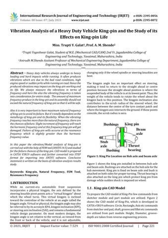
Figure 1: King Pin Location on Hob axle and beam axle Figure 1 shows the king pin installed in between hub axle and beam axle. Bushings are attached on the hub axle for the hub movement. King pin is fixed on beam axle and bush is attached on both sides for proper turning. Thrust bearing is also attached on the king pin which protect king pin from damage while sudden shock is imposed on wheel.
Keywords: King-pin, Natural Frequency, FEM Tool, Resonance Frequency
1.INTRODUCTION While no current-era automobile front suspension incorporates a physical kingpin, the axis defined by the steering knuckle pivot points acts a "virtual kingpin" about which the wheel turns. This virtual kingpin is inclined toward the centreline of the vehicle at an angle called the kingpin angle. Virtual or physical, the kingpin angle may also be referred to by its acronym KPA, kingpin inclination (KPI), or steering axis inclination (SAI), and remains a fundamental vehicle design parameter. On most modern designs, the kingpin angle is set relative to the vertical, as viewed from the front or back of the vehicle, and it is not adjustable,
© 2021, IRJET
|
Impact Factor value: 7.529
1.1 . King-pin CAD Model To prepare the CAD model of King-Pin few commands from sketcher module and part module are utilized. Figure 2 shows the CAD model of King-Pin, which is developed in CATIA v5R19 software. Circle, Rectangle, Axis etc commands from sketcher and pad, shaft, groove and fillet etc commands are utilized from part module. Height, Diameter, groovedepth are taken from reverse engineering process.
|
ISO 9001:2008 Certified Journal
|
Page 221