International Research Journal of Engineering and Technology (IRJET)
e-ISSN: 2395-0056
Volume: 08 Issue: 07 | July 2021
p-ISSN: 2395-0072
www.irjet.net
Cascaded H-Bridge Nine-Level Inverter for Solar PV Systems Hari Prasad R1, Dr. S.G. Srivani2 1PG
Student, Power Electronics, Department of EEE, RVCE, Bengaluru, Karnataka, India Professor and Dean, Department of EEE, RVCE, Bengaluru, Karnataka, India ---------------------------------------------------------------------***---------------------------------------------------------------------2Associate
Abstract – Conventional inverters have more THD, higher
switching losses and lower efficiency. Therefore, to overcome such problems multilevel inverters have evolved and are widely used in power applications and renewable energy systems. These inverters reduce the high switching losses and THD and maintain the efficiency using sinusoidal PWM method and thereby a smooth sinusoidal waveform at the load is recorded. In this proposed work, a cascaded H-bridge 9-level inverter is implemented along with the boost converters, solar PV array systems and filter circuits where as the 15-bus radial power grid system is connected at the load of the inverters through 11 kV step-down transformer. GA-Based MPPT controller is connected with solar PV panels to track the maximum power points of the load signal for boost converter. The filter circuits eliminate the THD and produce pure sinusoidal waveform. The proposed system records the values of THDs during simulation and they’re found to be 2.40 %, 0.38 % and 1.95 % for phase A, phase B and phase C respectively.
lead to the growth of Multilevel Inverter (MLI), the creation of multiple DC levels that combined into sinusoidal wave which reduces harmonic distortion. MLI topologies are introduced to be functioning under high frequency with lesser switching losses and higher efficiency [5]. Therefore, a 9-level cascaded multilevel inverter is designed and simulated to produces a lower THD content. Multilevel inverters are utilized generally in the regular applications due to the high voltage capacity and it delivers the multilevel with low composition with least concern in the exchanging gadgets [6].
Key Words: Solar PV Arrays, Boost Converters, MPPT Algorithm, Multilevel Inverters, Filter Circuits , 15-Bus Radial System, MATLAB/Simulink, FFT Analysis
1. INTRODUCTION The non-renewable energy sources such as fossil fuels and nuclear energy cause dangers, environmental pollutions and hazards due to green house effect. [1] This is one of the prime reasons why renewable energy sources like solar energy and wind energy have huge demands since they are freely available and is clean and non-exhaustible. Moreover, they are more popular and demanding due to advancements in power electronic techniques. Photovoltaic (PV) sources are used today in many applications as they have the advantages of effective maintenance and pollution free [2]. It is also witnessed that among these renewable energy sources solar PV energy is found to be the most promising energy [3].
1.1 Multilevel Inverter Conventional inverter has been used since the past decades in the field of industrial applications and power systems of lower power usage. Problems appeared when it comes to high power and medium voltages usage [4]. Conventional inverters are found that it no longer fulfils the requirement of voltage usage due to the incapable of reducing harmonic contents. It has high switching losses, lower efficiency and the lifespan of the systems due to long term constraining. This © 2021, IRJET
|
Impact Factor value: 7.529
|
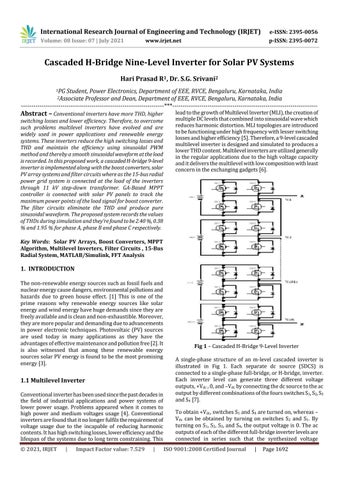
Fig 1 – Cascaded H-Bridge 9-Level Inverter A single-phase structure of an m-level cascaded inverter is illustrated in Fig 1. Each separate dc source (SDCS) is connected to a single-phase full-bridge, or H-bridge, inverter. Each inverter level can generate three different voltage outputs, +Vdc , 0, and –Vdc by connecting the dc source to the ac output by different combinations of the fours switches S1, S2, S3 and S4 [7]. To obtain +Vdc, switches S1 and S4 are turned on, whereas – Vdc can be obtained by turning on switches S2 and S1. By turning on S1, S2, S3, and S4, the output voltage is 0. The ac outputs of each of the different full-bridge inverter levels are connected in series such that the synthesized voltage ISO 9001:2008 Certified Journal
|
Page 1692