International Research Journal of Engineering and Technology (IRJET)
e-ISSN: 2395-0056
Volume: 08 Issue: 07 | July 2021
p-ISSN: 2395-0072
www.irjet.net
GAS INSULATED TRANSMISSION LINE (GIL) Mr. Siddharth Mahesh Remane1, Mr. Balasaheb Mansing Patil2, Mr. Deepak Dattatray Patil 1Student,
Yashwantrao Bhonsale Polytechnic, Sawantwadi, Maharashtra, India Department of Electrical Engineering, Yashwantrao Bhonsale Polytechnic, Sawantwadi, Maharashtra, India 3Professor, Head of the Department, Department of Electrical Engineering, Yashwantrao Bhonsale Polytechnic, Sawantwadi, Maharashtra, India ---------------------------------------------------------------------***---------------------------------------------------------------------2Professor,
Abstract - Considering the current electrical energy
answer to the increasing energy needs of our urban society and to the extension and reinforcement of the present electricity Transmission and distribution; GIL is a key to solve this issue. The outstanding features of a GIL system are its high transmission capacity, superior electromagnetic compatibility (EMC) to any other transmission system, low losses, high safety (no fire hazard) and flexible installation options makes it more fit in the working environment. They hardly impact on the landscape, and their minimal electromagnetic radiation means they can also be used close to, or even within buildings. They are suitable for providing a continuation for overhead lines underground, connecting power stations to the power network, or as a space-saving way to connect major industrial plants to the public grid.
scenario, transmission plays a very important role. The generating factors comprehensively are of no use if transmission does not take place. Wherein the generation is made at the most effective end it’s a challenge before the engineers to transmit this generated supply with minimal losses. There are a number of losses taking place in the OH as well as the UG systems hence to overcome this we use a transmission system i.e. GIL (Gas Insulated transmission Line). Going through this paper we promptly understand the outstanding features of GIL system that is, its high transmission capacity, superior Electromagnetic compatibility (EMC) to any other transmission system and most importantly its high safety. The laying basically can be done above and below the ground without disturbing its layout. Since GIL provides good heat dissipation properties it can be used for high transmission system. In this GIL, tubular Aluminum conductor is used which is partly insulated by the composition of N2 and SF6 gas. Since SF6 beholds adverse environmental effect its research is still in process.
2. CONSTRUCTIONAL FEATURES
Key Words: Underground Cable, GIL, Installation Methods, Insulating gas (SF6, N2), EHVAC, HVDC.
1. INTRODUCTION High voltage underground cables for power transmission have been in use for many years and number of different technologies has developed over this progressive years. Solid insulation cables have limits when it comes to the voltage that can be carried safely, and oil impregnated paper cable are also limited in the capacity. Gas insulated transmission lines (GIL) provide technical, environmental and operational features which make them a very good alternative wherever the transmission of extra high voltage (EHV) and extra high currents (EHC) is needed within restricted space. The GIL was first introduced by the scholars of MASSACHUSETTS University in Germany in the late 1970’s. Their high transmission capacity (up to 3,000 MVA through one GIL circuit) and multiple advantages for transmitting bulk electric power in such complex sites networks over short and long range distances in a safe and environmentally friendly way represents one of the major challenges of the coming decades. GIL provides an effective technological
© 2021, IRJET
|
Impact Factor value: 7.529
i
ii
|
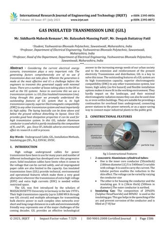
fig 1.Constructional Features 2 concentric Aluminium cylindrical tubes: One is the inner core conductor (50cmthick) (180mm diameter) (C/S is 5400mm2) variable with voltage. It is used to carry the current. The tubular portion enables the reduction in the skin effect. The voltage can be varied by varying the conductor size The other is for housing the conductor and the insulating gas. It is (18cm thick) (500mm in diameter).The outer conductor is earthed. Insulating Gas: The composition of 20%SF6 (Sulphur HexaFluoride) and 80%N2 is used as the insulating gas. This gas helps in the quenching of the arc and prevent corrosion of the conductor and is filled at (7-8) bar
ISO 9001:2008 Certified Journal
|
Page 1506