International Research Journal of Engineering and Technology (IRJET)
e-ISSN: 2395-0056
Volume: 08 Issue: 06 | June 2021
p-ISSN: 2395-0072
www.irjet.net
Clean in Place System using PLC Mrs. Sheetal Pawar1, Mamleshwar Takate2, Yogesh Masal3, Prajakta Gophane4 1Lecturer, Electronics and Telecommunication Department, MIT Polytechnic, Pune, India
2, 3, 4Students, Electronics and Telecommunication Department, MIT Polytechnic, Pune, India
---------------------------------------------------------------------***---------------------------------------------------------------------Abstract: In dairy , food industries , pharmaceutical industries, we required more proper hygiene to maintained quality and test of the product . this paper focused on the more easier , reliable and advance method to clean the equipment like tank, valves , pipes , etc. this method providing tank cleaning without introspect of human being . This paper focused on the tank cleaning of fully automated system and safe to the environment. Automation is done using PLC (Programmable Logic Controller) .
2.3 Time : If the chemical is more concentrate then less timeis required for cleaning and diluted chemical required more time. 2.4 Mechanical Force: This force is useful for removal of soil particles with the help of different equipments like brush, air compressor.
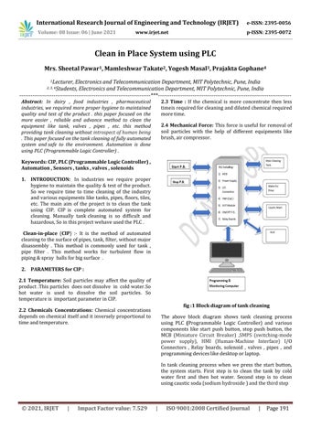
Keywords: CIP, PLC (Programmable Logic Controller) , Automation , Sensors , tanks , valves , solenoids 1. INTRODUCTION: In industries we require proper hygiene to maintain the quality & test of the product. So we require time to time cleaning of the industry and various equipments like tanks, pipes, floors, tiles, etc. The main aim of the project is to clean the tank using CIP. CIP is complete automated system for cleaning. Manually tank cleaning is so difficult and hazardous, So in this project wehave used the PLC . Clean-in-place (CIP) :- It is the method of automated cleaning to the surface of pipes, tank, filter, without major disassembly . This method is commonly used for tank , pipe filter . This method works for turbulent flow in piping & spray balls for big surface . 2. PARAMETERS for CIP : 2.1 Temperature: Soil particles may affect the quality of product .This particles does not dissolve in cold water. So hot water is used to dissolve the soil particles. So temperature is important parameter in CIP. fig :1 Block diagram of tank cleaning
2.2 Chemicals Concentrations: Chemical concentrations depends on chemical itself and it inversely proportional to time and temperature.
The above block diagram shows tank cleaning process using PLC (Programmable Logic Controller) and various components like start push button, stop push button, the MCB (Miniature Circuit Breaker) ,SMPS (switching-mode power supply), HMI (Human-Machine Interface) I/O Connectors , Relay boards, solenoid , valves , pipes , and programming devices like desktop or laptop. In tank cleaning process when we press the start button, the system starts. First step is to clean the tank by cold water first and then hot water. Second step is to clean using caustic soda (sodium hydroxide ) and the third step
© 2021, IRJET
|
Impact Factor value: 7.529
|
ISO 9001:2008 Certified Journal
|
Page 191
International Research Journal of Engineering and Technology (IRJET)
e-ISSN: 2395-0056
Volume: 08 Issue: 06 | June 2021
p-ISSN: 2395-0072
www.irjet.net
is to clean by phosphoric and nitric acids , sodium hypochlorite and Peracetic acid respectively. Acids and caustic soda are poured into the tank with the help of solenoid valves connected to the tank. All this process is operated through the computer.
CIP Station: In CIP station all the components are present and assembled. All processes are done in CIPstation. 3. PLC AND ITS WORKING PRINCIPLE:
General Arrangement of tanks:
fig3: Block diagram of PLC PLC is a programmable logic device. It is used for specific function like counting, timing, logic operation, arithmetic and in control process. It is brain of the automation industry.
Fig2: General tank arrangement Tank arrangement is done to get followings objectives ● Fluids like Water, Caustic Soda, Phosphoric and Nitric acids, Sodium Hypochlorite (Hypo) and Peracetic Acid (PAA) are present in Tanks higher than the main tank to be cleaned so as to utilize the Gravity for dispensingfor reducing the pump cost.
It consist of CPU, I/O module, memory, programming device and power supply. PLC works in three steps; check input status, execute program, update the output status. PLC also work in three modes; run mode, stop mode and, reset mode.
● All these four tanks are connected to the solenoids by using R.O. Pipes. ● The Main Tank is located at the bottom which has a Motor (Pump) inside and Solenoid Valve at the bottom of the Tank to drain the cleaning agents out. ● This Process is the integration of CIP with PLC Panel enables end to end Process without human Involvement.
Fig 4: PLC (Mitsubishi Graphic OperationController)
● The Process repeats until the Raw material is finished or the Emergency Stop Push button is pressed.
© 2021, IRJET
|
Impact Factor value: 7.529
|
ISO 9001:2008 Certified Journal
|
Page 192
International Research Journal of Engineering and Technology (IRJET)
e-ISSN: 2395-0056
Volume: 08 Issue: 06 | June 2021
p-ISSN: 2395-0072
www.irjet.net
Fig5: Hardware stand
Fig 6: Tanks
© 2021, IRJET
|
Impact Factor value: 7.529
|
ISO 9001:2008 Certified Journal
|
Page 193
International Research Journal of Engineering and Technology (IRJET)
e-ISSN: 2395-0056
Volume: 08 Issue: 06 | June 2021
p-ISSN: 2395-0072
www.irjet.net
Figure 5 and 6 shows the model of the project, in upper part of the hardware stand GOC type PLC is placed. At middle MCB (Miniature Circuit Breaker) of 6A is used to provide over voltage and over current protection to the project. At lower side terminal block is given to connect input output devices to the circuit.
Ms. Prajakta Balasaheb Gophane is a third year diploma student in electronics and telecommunication engineering student at MIT Polytechnic, Pune, Maharashtra, India.
The tanks are connected together using R.O pipes of 4 mm. diameter and solenoid valves are used. Tank is made from high quality of plastic and polycarbonate material.
Mr. Yogesh Madhukar Masal is a third year student diploma in electronics and telecommunication engineering student at MIT Polytechnic, Pune, Maharashtra, India.
Ladder Diagram: Ladder Diagram is the simple and easier programming language for PLC programming. It is easier to understand and programming. This language is mostly used in industry. 4. Conclusion /:- This system will economize the cleaning procedures in a processing plant, but repeated use may cause the buildup of thermoduric organisms in the pipelines and subsequently in to the pasteurized milk. So timely revision of the cleaning strategies should be carried out to obtain good product quality. References[1] Bremer, P. J. and Seale, R. B. 2010. Clean- in-Place (CIP). Encyclopedia of Industrial Biotechnology: Bioprocess, Bio separation, and Cell Technology. pp 1–8 [2] Vlkovai, H, Babakai, V., Seydlova, R., Pavliki, I. and Schlegelovai, J. 2008. Biofilms and hygiene on dairy farms and in the dairy industry, sanitation chemical products and their effectiveness on biofilms a review. Czech J. Food Sci. 26: 309–323 [3] Tamime A.Y. and Robinson R.K. 1999. Yoghurt: Science and Technology. Woodhead Publishing Ltd, Cambridge pp 41-156 [4] Merin, U., Guiziou, G., Boyaval, E. and Daufin, G. 2002. Cleaning-in-place in the dairy industry: criteria for reuse of caustic (NaOH) solutions. Lait. 82:357–366
5. BIOGRAPHIES Mrs. S. K. Pawar currently working as a Lecturer in the Department of Electronics and Telecommunication Engineering at MIT Polytechnic, Pune, Maharashtra, India. Mr. Mamleshwar Sunil Takate is a third year diploma student in electronics and telecommunication engineering student at MIT Polytechnic, Pune, Maharashtra, India
© 2021, IRJET
|
Impact Factor value: 7.529
|
ISO 9001:2008 Certified Journal
|
Page 194