51 minute read
Manufacturer qualification audit

from IRJET- A Review of Design, Manufacturing of Grid Tied PV Inverter and its Impact on Site Performance

Volume: 08 Issue: 05 | May 2021 www.irjet.net p-ISSN: 2395-0072
norms and standards during routine checks and factory acceptance test (FAT) as per ISO 2859. This standard is acceptance sampling system for inspection in terms of the acceptance quality limit (AQL). FAT is performed as per mutually agreed MQP to assure that the equipment meets all the contractual requirements and any issues if any can be addressed before product is dispatched to customer site and thus saves time and money over fixing issues at site.
Advertisement
Fig -17: FAT process parameters
Incoming quality checks (IQC) of raw material for production avoids potentially non-conformity, prior to moving it to the production or assembly line. Inspection is done on parts in accordance with customer purchase order, drawings and standards and other relevant documents. Statistical analysis is the preferred method of performing inspection. In some cases, inspection may be omitted for non-critical parts or if supplier is certified vendor. List of critical components normally considered for inspection are IGBT, Inductor chokes, DC link capacitors, busbars, switchgears, fuses, transducers (CTs), fans, electronic boards etc. Manufacturing quality process is the guarantee for good product qualityand to understand how effective the process performs is to measure itsKPIs. Some of commonly used KPI are First Pass Yield (FPY), On Time Delivery (OTD) and Defects per Unit (DPU). FPY measures the percentage of product made correctly without any rework activitywhile OTD indicates the rate of finished product produced (delivered) intime. DPU identifies the number of defects per manufactured unit. A defect is an occurrence of non-conformance to customer requirements and it is possible for a single product to have multiple defects.
Traceability in manufacturing is an activity of collecting and managing information regarding what has been done in manufacturing processes from acceptance of raw materials, assembly process and shipment of products. If in case of product quality problem occurs, traceability record helps the manufacturer to takes effective measures promptly by recall, repair or replace of damaged parts of theproducts.

Factory (process) certification plays a key role to be a global player in the marketplace, to maintain consistency and quality of a product, process, or service across the nations. Usually, inverter manufacturer certifies for ‘Design, manufacture, supply and service’ of the inverter product’. ISO, UL, CE are few agencies in place for this type of certifications. Certification issued is by independent certification bodies but accredited by the IAF (The International Accreditation Forum) member to be internationally recognized. Some reputed and global certifying bodies are TUV Nord, DNV GL BV, etc. International Organization for Standardization (ISO) ensures that products and services are safe, reliable and of good quality. Some of the necessary ISO standards applicable for inverter manufacturers are:
ISO 9001 specifies requirements for a quality management system (QMS) in an organization to demonstrate the ability to consistently provide products and services that meet statutory and regulatory requirements. Manufacturer documents its QMS to clearly and concisely identify their processes, procedures and work instructions in order to explain and control how it meets therequirements of ISO 9001:2015.
A process states what needs to be done and why. A procedure states how the process needs to be done. A work instruction explains how to carry-out the procedure. Standard Operating Procedure (SOPs) are top-level documents that tell employees which actions to take under various circumstances and Work Instructions (WI) describe those actions in detail. WI ensures that the manufacturing processes are consistent, timely and repeatable. Work instructions narrows to an individual task within an SOP.
ISO 14001 sets out the requirements for an environmental management system (EMS) which helps organization to improve their environmental performance through more efficient use of resources and reduction of waste.
ISO 45001 specifies requirements for an occupational health and safety (OH&S) management system, which provide a structured framework for ensuring a safe and healthy workplace thus preventing injury and ill-health. The UL certification is a North American product certification from Underwriter Laboratories (UL) shows that the product in question is tested to meets US and Canadian safety standards. UL audit includes inspection of UL rated inverter components, verify that the manufacturer has the required test equipment and are functioning properly and are calibrated at least once annually. Review the manufacturer's records to assure that the tests (relevant to routine safety and grid abnormality tests as in UL 1741, IEEE 1547, UL 62109) are being conducted and appropriate action is taken with respect to failures and rejections. CE Mark is a symbol affixed to products before it issold to European market, indicating that the product meets all the requirements of the relevant recognized European harmonized performance and safety standards.
4.6 RAM Analysis
RAM refers to reliability, availability,and maintainability. It addresses the weakest link in a product which helps to improve the overall product reliability.
Volume: 08 Issue: 05 | May 2021 www.irjet.net p-ISSN: 2395-0072
Reliability is the probability of aproduct, that will perform its intended function adequately for a specified period of time. It defines the failure frequency and determines the uptime patterns. Availability is the percentage of uptime over the time horizon and is determined by reliability and maintainability. Maintainability describes how soon a unit can be repaired, which determines the downtime patterns. Failure Mode and Effects Analysis (FMEA) is one of several tools to conduct RAM analysis. It is a methodology aimed in organizations to anticipate failure during the design stage by identifying all of the possible failures in a design or manufacturing process. It focuses on the risk assessment detection, elimination, and/or mitigation of critical risk events. Two types of FMEA are: Design Failure Mode Effects Analysis (DFMEA) Process Failure Mode Effects Analysis (PFMEA).
DFMEA helps to analyzepotential failures of a product design whereas PFMEA helps to analyze potential failures of a particular process during manufacturing. Risk Priority Number (RPN) is a numerical assessment of therisk priority level in failure mode analysis. It is product of severity of failure mode, potential of failure occurrence and capability of failure detection and each is ranked on a scale of 1 to 10.
RPN = Severity x Occurrence x Detection
Root Cause Analysis (RCA) is problem-solving process and is an integral part of continuous improvement used to identify the root causes of a fault. FMEA is a proactive method i.e., looks ahead to what could happen while RCA i.e.,analyzing a root cause of a problem occurred is reactive. Commonly used tools for root cause analysis are Pareto Chart, 5-Whys Analysis, Fishbone Diagram, 8D (eight disciplines), Failure Mode and Effects Analysis, DMAIC (Define, Measure, Analyze, Improve, and Control(DMAIC)etc.
4.7 Guarantee and Warranties
i. Warranty Against Workmanship or Materials
Manufacturer guarantees the product for a period after delivery from factory (Ex–Works), is free from any defects related to the components or manufacturing process, which may prevent the normal operation, installation, and maintenance under proper conditions. Normally inverter comes with a standard 5-year workmanship warranty and is extendable with typically 2-or 3-year increments. Extended warranty from inverter manufacturer protects against unforeseen costs from issues that may arise over the life of plant. This future-proof assurance provides added confidence to financiers, developers, and utilities as it includes coverage of spares, remote and onsite diagnostic, and repair services. Independently verified MTBF product data also serves beneficial to customer over purchasing extended warrantees from inverter manufacturer.
ii. Availability (Uptime) Guarantee
Availability is defined as the percentage of time a product is able to produce electricity and thisguarantee is based on the inverter not providing power due to inverter failure. Inverter manufacturers offer uptime and guaranteed availability fortheir product as a part of service package in service level agreement (SLA) by capturing data from years of field operation, to take the mean time between failures and other reliability statistics. Based on service contract if availably goes below over a specified timeframe the manufacturer will pay or accrue a credit for the customer at a fixed rate either per kWh lost (based on solar irradiance) or at a flat rate per kWac (based on time down) that would have been delivered if the inverter was fully functional. Exceptions for this calculation not counting as downtime includes, external grid events, maintenance that requires a shutdown of the inverters etc.
With ongoing trends in industry, inverter manufacturers offer ≥ 99% annual availability guarantee. Manufacturer costs critical spares and recommend customer preventative maintenance plan with scheduled inspections, checks and measurements in inverter to support this guaranteed uptime.
4.8 Serviceability
It is critical to customer to understand the importance of after sale service support from the product manufacturer to attend repair or replacements during breakdown and maintain high uptime throughout lifecycle of the product. Region wise warehouse (for spares) availability, competency and team size of service engineersare some of serviceability factors considered. Large-scale utility customers prefer advanced monitoring and diagnose software installed in inverters where manufacturer can remotely monitor, diagnose, and troubleshoot inverter (even on dedicated smartphone apps)and reduce dependency on maintenance staff and services. Common KPIs covered in service level agreement (SLA) are: Acknowledgement time also called reaction time is the time between detecting the problem (receipt or noticing ofalarm/fault) at site and itsacknowledgement by the manufacturer or its Authorized Service Provider (ASP) to deliver solution and /or dispatch a technicianto site. Intervention time is the time the manufacturer takes to reach the site from the moment of acknowledgement.
Thistime assesses the capacity of the manufacturer,how fast they can mobilize the service team and be on site. Response time is the sum of acknowledgement and intervention time. Minimum response times are guaranteed on the basis of fault classes classified on the basis of the unavailable power and the consequent potential loss of energy generation. Resolution time or repair time is the time to resolve the fault starting from the moment of reaching the site. This time is generally not guaranteed, because resolution often does not depend totally on the service contract.
Volume: 08 Issue: 05 | May 2021 www.irjet.net p-ISSN: 2395-0072

Fig -18: Key service deliverable KPIs
4.9 Pricing
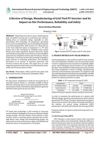
Inverter price depends on state of art design, technology, ratings, add-on features, warranties, and volume of purchase. Manufacturer that demonstrates, or the buyer perceive, that the product quality is higher than similar competing product often support premium pricing. Inverter manufactures incorporates the cost of anticipated repair or replacements if any extended warranty period into their pricing structure. Inverter installation cost and plant BOS cost due to selected inverter also matters to customer on inverter pricing. Market for utility scale solar projects in India is dominated by central inverters. ‘The bigger, the better’ seems to be the mantra-owing to the reason that inverter price depends on its power capacity. Each year, the National Renewable Energy Lab performs a costbenchmark
Fig -19: Solar inverter pricing (Q1-2020 NREL Report)
4.10 Bankability
The bankability (i.e., financial health) of the supplier and hence their credibility is very important for investors. Considering utility-scale projects are expected to deliver 25 years of energy production, and investor making huge investment ensures, the key component suppliers like invertermanufacturing company is around for the life of the plant to support the project in terms of service and availability of replacement parts and secure project financing. As supplier bankability improves, financing risk is reduced, and this leads to lower financing costs and greater viability of projects. Competition among inverter brands and reduced tariffs in PV solar market has caused numerous acquisitions and exits in recent times and hence there are very few (tier 1) inverter companies surviving globally. The best warranty does not matter if the manufacturer is not around to back it up.
4.11 Supplier Qualification Audit
It is challenging for a inverter manufacturer to keep consistency in material grade, type used and their seamless integration of mechanical and electrical components, change in sub-venders and skilled manpower time to time at factory as they are the main cause for variation in maintaining the consistency of manufacturing process and quality. Hence manufacturers are on their toes to offer cost-effective product. This qualification process assesses manufacturer reliability, capability, capacity, and credentials. Customer expects that inverter product manufactured and delivered must perform defect free for its specified design life. This audit supports customer to have diligence to check control and consistency ofdesign and manufacturing process. Some of qualification parameters includes, manufacturing company organization, its mission, factory capacity & experience, licenses, certificates, production line, manufacturing process, machineries, and equipments, quality control plan, vendor management program, engineering process & design change control management, resolution of customer (site) complaints. As a part of the qualification audit, customer provides audit scores to manufacturers.
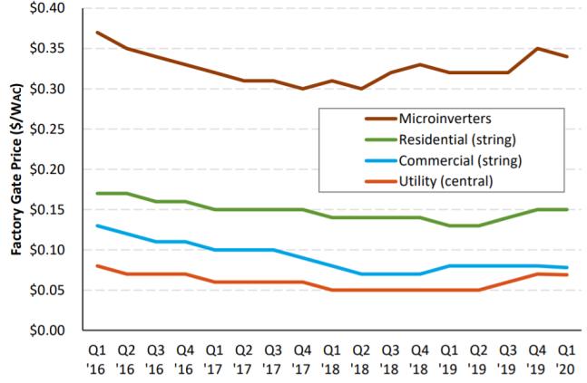
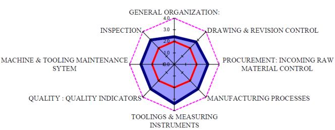
Fig -20: Typical graphical representation of audit score
5. INVERTER FUNCTIONALITY
Solar inverters produce alternating current with PWM technique i.e.,high frequency chopping dc voltage withIGBTs. This rapid switching generates high dv/dt and di/dt and hence electromagnetic interference (EMI) noise from inverter. Multi-level topology and higher order LCL filters in inverter determines the quality of output fed to grid to comply to standards like IEEE, IEC, and local grid codes. Solar inverter in process of performing its main task of convertingdc to ac power, has three other important tasks: MPPT Control
Inverter input dcpower is not all time constant as PV solar array is nonlinear i.e., varies with change in weather conditions like irradiation and temperature. Maximum power point tracker (MPPT) controller algorithm controls dc input voltage and current to provide maximum dc power and thus improves the system efficiency. The MPPT control algorithm in inverter is based on many techniques but Perturb and Observe (P&O) is used by most of the inverter manufacturers due to its simplicity and effectiveness.
Volume: 08 Issue: 05 | May 2021 www.irjet.net p-ISSN: 2395-0072
Inverter control and protection Inverter control performs grid synchronization, voltage modulation, dc voltage regulation and current loop control. Inverter when synchronized to grid delivers active or reactive power based on PPC reference. Protection within inverter is set based on internal and external faults and as per specified grid codes. Internal ac fuses and ac breakers restrict damage to inverter. Input dc fuses protect the inverter dc circuit and dc input cables in case of short-circuit scenario. Inverter protects itself against thermal overload by power foldback orde-rating output power generation.
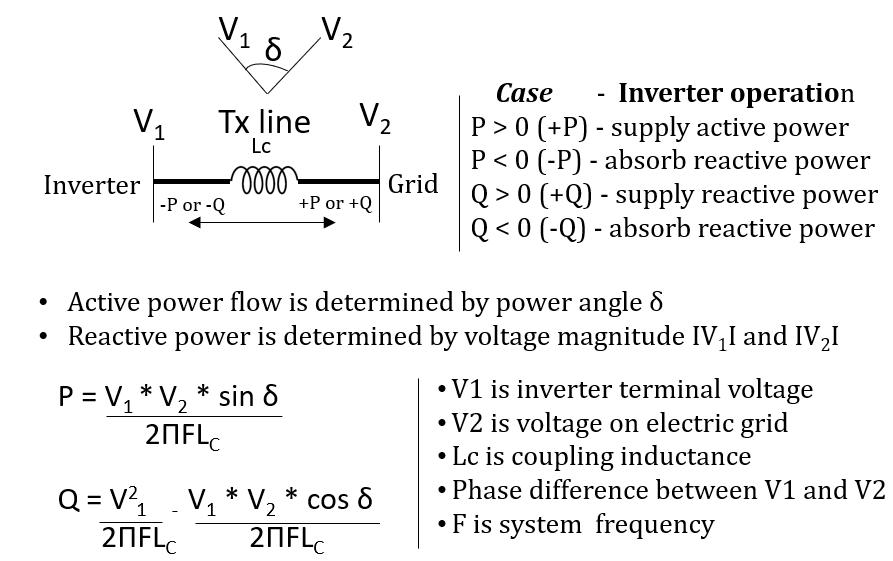
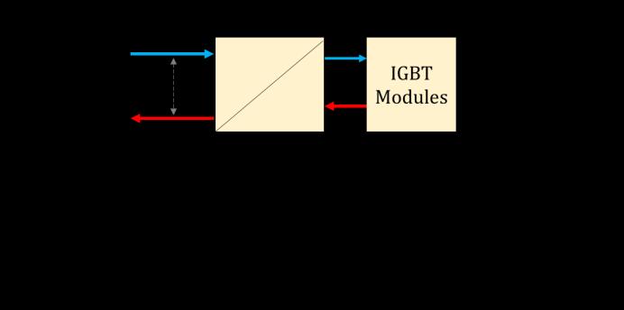
Fig -21: Typical inverter response in event of grid fault Active and reactive power control Inverter delivers active and reactive power as demanded by PPC and as per inverter P-Q capability based on grid voltage, ambient temperature, and solar irradiance. Inverter synchronized to grid, offsets its current waveform from utility by delaying switching which creates sub-cycle energy exchange between inverter dc link and grid. This causes increase or decrease in grid voltage based on direction of reactive power flow.
Fig 22: Inverter block diagram: Power and Control According to the theory of instantaneous power, the reactive and active power of inverter can be regulated by changing the amplitude and the phase of inverter output voltage. The active and the reactive power compensation are realized simultaneously. The reactive power compensation feature improves the utilization factor of the inverter during nonsunshine hours or at night, to support grid voltage stabilization.
PV inverter runs in current control mode where active (Id) and reactive (Iq) current are constantly controlled. Under normal operation only active power is drawn from PV array and injected into grid. During grid fault i.e., when voltage dips, grid requires PV inverter to inject reactive power (Iq ά voltage dip) to support grid voltage. The active power (P) and reactive power (Q) flowing between the inverter and the grid is obtained by means of a phase analysis and isexpressed as;
Inverter also supports reactive power generation according to the defined curves such as Q(U), Q(P), and cosϕ (P). In Q(U) control mode, reactive power generated by the inverter depends on the grid voltage whereas in Q(P) controlmode, the reactive power generated by the inverter is function of active power. In cosϕ(P) control mode, the reactive power generated by the inverter depends on the active power. Historically, utilities were asked generators to disconnect from grid during abnormal voltage abnormality. But now inverters acting as distributed generators can easilycontrol VAR or change PF through switching topology and can quickly become capacitive or inductive i.e.,source andsink reactive power, theutilities are now asking inverters to keep connectedduring grid fault and support grid to stabilize with VAR control feature.


Centralized power stations often require power to be transmitted over long distances. But reactive power which is essential to stabilize gird is difficult to transport over long distance. So solar inverters acting as distributed generators (DG) installed close to the load, generates and absorbs reactive power to support grid stability.
6. Inverter Design CTQs
Design of an inverter product is measured in CTQs (critical to quality) parameters. Considering on-going market trends, typical CTQs considered by inverter product manufacturer are as listedbelow:
Modularity: -Redundant design to reduce downtime Utilization: -Overload ≥ 120% -High DC / AC ratio ≥1.5 Conversion efficiency: © 2021, IRJET | Impact Factor value: 7.529 | ISO 9001:2008 Certified Journal | Page 4685
Volume: 08 Issue: 05 | May 2021 www.irjet.net p-ISSN: 2395-0072
-ղmax >99% -ղeuro ≥98.8% Auxiliary power consumption: -Less than 0.5% of Pnom Thermal Performance -More than 55°C and upto 60°C Availability -More than 99.5% Footprint -Reduced weight ≤ 1.5 Kg/kW -High power density ≤5 m3 /MWac BOM cost (standard) ≤10 lac INR (or 13.5 k$) per MWac High reliability with better design margins in terms of
MTBF Reduced MTTR with direct accessibility and reduced replacement time for critical components.
7. PERFORMANCE
Conversion efficiency and cooling are the two most important factors decides PV inverter performance which is dependent ondesign of power electronics (IGBTs) switching circuit and thermal management. Next generation power electronic devices like IGBTs with Silicon Carbide (SiC) technology has increased power conversion efficiency compared to conventional silicon (Si) devices. SiC based power devices switch faster, operate at much higher switching frequencies and temperatures, managing the same level of power as Si devices but at approximately half the size. This enables dramatic increase in power density and allows simpler cooling design and fewer parts, thus a smaller and more compact inverter footprint.
7.1 Inverter Efficiency
Losses in inverter are due to factors like conversion loss, losses associated with magnetics, copper, and selfconsumption. Inverters in process of converting dc to ac power, produces loss also called conversion loss due to heat generating during IGBT switching. This loss decides inverter conversion efficiency. For e.g., a 1 MW inverter with 98% conversion efficiency mean it has 2% or 20-kW loss. For a given inverter design, efficiency depends on ambient temperature and DC voltage level. Efficiency is more at minimum MPPT voltage due to reduced PWM switching losses. Manufacturer specify efficiency at minimum MPPT voltage level and standard operating temperature around 25°C as per design. Conversion efficiency is not a fixed number but a curve which fluctuates with the input power or voltage. Commonly measured efficienciesare: Euro, CEC and Peak or max efficiency. Practically inverter operates at its peak efficiency only for a small period of the day. And this is why the weighted efficiencies like Euro (European) and CEC (California Energy Commission) have been developed to indicate how an inverter might perform throughout the day. Euro and CEC efficiencies differs on loading levels and based on climatic conditions in Europe region (for Euro) and California including US south-west regions (for CEC)respectively.
Table -13: Euro and CEC efficiency weightage table Euro Efficiency % Loading 5 10 20 30 50 100 weight in pu 0.03 0.06 0.13 0.1 0.48 0.2 CEC Efficiency % Loading 10 20 30 50 75 100 weight in pu 0.04 0.05 0.12 0.21 0.53 0.05
Table -14: Typical efficiency values at different DC voltage levels and loading points
Output % 5% 10% 20% 25% 30% 50% 75% 100 %
Vmin 97.0 2 98.2 6 98.8 98.8 98.8 2 98.7 5 98.5 4 98.2 9
Vnom 96.2 6 97.7 9 98.4 98.4 8 98.5 1 98.4 7 98.2 8 98.0
Vmax 95.7 97.5 6 98.2 6 98.3 6 98.4 98.3 7 98.1 8 97.9 3

Fig -23: Efficiency curve at different dc voltage levels Based on efficiency at different loading (atmin MPPT) and weightages as in above tables, the Euro and CEC efficiencies are calculated as below:
Euro Efficiency
= 0.03 x 97.02 + 0.06 x 98.26 + 0.13 x 98.74 + 0.1 x 98.82 + 0.48 x98.75 + 0.2 x 98.29 = 98.58%
CEC Efficiency
= 0.04 x98.26 + 0.05 x98.74 + 0.12 x 98.82 + 0.21 x 98.75 + 0.53 x 98.54 + 0.05 x 98.29 = 98.60% Peak (Max) efficiency = 98.75% -> 98.8% As per IEC 61683, the worst accuracy of the conversion efficiency is givenas: Max deviation = ±0.2 * (1 − η) * η%. So, for ηmax of 98.5%, the worst accuracy is ±0.3%. This is below the tolerance value of measuring instrument like precision power analyzer Yokogawa WT3000 which is < ±0.2%.
7.2 Thermal Management
The performance and lifetime of an inverter depend on its operating temperature. Hence better thermal management is very essential for entering the next era of PV inverter. The most heat generating components with-in an Inverter are: IGBT modules Inductor chokes Aux. internal transformers
Volume: 08 Issue: 05 | May 2021 www.irjet.net p-ISSN: 2395-0072
Control supply (SMPS) units Current carrying busbars also contributes to some extent
The operating temperature of components selected is normally more than the temperature experienced within enclosure. Considering there existstemperature difference (∆T) between the ambient and the anticipated product enclosure, together with the volume of air, the amount of heat that can be removed from the enclosurecan be determined. The thermal design of aproduct begins with the method of determining the cooling method. The selection of cooling methods is based on the heat flow density, temperature rise, reliability, size, weight, and cost. Most popular cooling technique includes (forced) air cooling, liquid cooling, heat pipes system. In forced cooling, the fans are always used with filters to reduce the dust entering the enclosure. As a thumb rule, a filter reduces the airflow by about one third. Therefore, when selecting the fan size, the free flow CFM should be three times the required air flow rate to provide sufficient cooling. In forced air-cooling method, the fan capacity selected to remove the amount of heat with the given temperature differential is calculated as per below relation:
Air isrelatively a poor transport mediumof removing heat and is not so effective for large power equipments. Hence alternative coolant medium like liquid cooling, heat pipes is adopted. In liquid cooling, the required coolant flow rate is calculated asper relation shown below:
Forced air cooling is simple, reliable, easy to maintain, relatively low in cost and hence is popular cooling method. Liquid cooling is effective evenin site located in desert but is less reliable due to more maintenance issues. Heat pipe works on the principles of both thermal conductivity and phase transition to effectively transfer heat between two solid interfaces. Heat pipes technology delivers the performance of water cooling with use of air cooling. It containsno mechanical moving parts and typically require no maintenancewhich makes the inverter suitable for outdoor utility-scale PV plants.
8. INVERTER RELIABILITY
“Product Reliability is defined as the probability that a product will perform its required function, subjected to stated conditions, for a specific period of time’’. Product reliability is quantified in MTBF (Mean Time Between Failures) for repairable components and MTTF (Mean Time to Failure) for non-repairable components. Performance guarantees and longer warrantees of PV products is the need the industry. Inverter is considered as a weak link in PV systems, and very few inverter manufactures provide a warranty beyond 5 years. Asproject paybacks are typically more than 5 years, customers push inverter manufacturers to demonstrate higher product reliability. Reliability for solar inverter increases with reduced parts count, number of wired connections and increased design safety margins on its critical components. Reliability (R) is given by R=e(-λt). As an example, for failure rate (λ) of 0.5%, reliability for one year (or probability of inverter not failing within one year) is 0.995 or 99.5%. For 10 years, this will be 95.1%. Another parameter used to check failure frequency is the mean time between failures (MTBF) and is given by MTBF = (1/ failure rate). In this case for a failure rate of 0.5 %, the expected time between failures is 1/0.005 = 200 inverter-years.
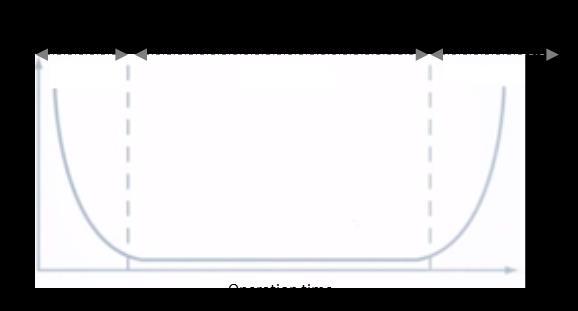
Reliability in terms of MTBF is given by R= e-t/MTBF Failure Rate (ƛ) is defined as the frequency with which an engineered system fails as defined by reliability engineering. It is the most common metric for measuring the reliability of inverters.The failure rate over time follows a curve that looks like a bathtub which has three zones: Infant mortality, useful life and wear out.

Equation exponential modelling of the bathtub curve is given by: P(t) = e-t/MTBF
Fig -24: Typical bathtub curve of a product Infant mortality rate refers to the rate of inverter failure based on design, manufacturing, shipping, installation and operating at the initial phase. After stabilization, the product enters into its useful life. In this phase the product matures, and the failure rate becomes nearly constant. This is common time frame for making reliability predictions. As components begin to fatigue or wear out, failure occur at increasing rates and MTBFs calculated in this phase is no longer applicable.
Volume: 08 Issue: 05 | May 2021 www.irjet.net p-ISSN: 2395-0072
MTBF is the inverse of the failure rate. It is a statistical measure and cannot predict (accurately) failure on any single unit or sample but on a lot. Low component count is considered as most fundamental rule of design for reliability and the reliability of a system is the product of the reliabilities of all the individual components. For e.g. if each component has an annual reliability of 99.99 percent means, there is only a 0.01% chance of failing in a year.
MTBF = 1/ (sum of all the part failure rates) For MTBF of 250,000 hours, and operating time of 5 years (43,800 hours), the probability that the product will work for time ‘t’ without failure is given by:
P(t) = e-t/MTBF = e-43800/250000 = 0.8392 which means that there is an 83.9% probability that the product will operate for the 5 years without a failure, or 83.9% of the units in the field will still be working at the 5year point. Cooling and thermal management plays an important role in design for improved reliability, as the operation life of product drops by half for every 10°C rise. If MTBF of a product is calculated at lower temperature say 25°C, and it is operated at higher temperature say 55°C. then product MTBF at 55°C will be one eighth. Reliability testing is a critical component of inverter product development and production for performance to maintain near perfect uptime. For a truly reliable product, quality begins at the design table. Quality control ensures, prior to assembly each component is individually inspected to confirm there is no manufacturing quality defects.
9. SAFETY
Solar Inverter as a product may resemble to normal PWM based variable frequency drive(VFD), but it is important to recognize that it also acts as a generator. Electricity comes from two sources in a solar inverter i.e.,from the utility grid and solar PV array. Even when main AC circuit breaker is shut off, the PV system will continue to supply power, and this requires extra caution on safety of personal during operation, service, and maintenance. Voltage surge and arc flash are other major incident occurrencesin PV plants as most of the power equipment are exposed to outdoor installation, high dc/ac ratio and high voltage (1500V) system.
9.1 Integral Isolation Safety
Based on design and applicable compliance, an inverter consists of protection mechanism like circuit breakers, contactors and fuses at its dc input and ac output circuit. To facilitate repair and maintenance safety,a separate (exterior to inverter) isolation may require even if one such is included within the inverter.
The dc isolator meant for inverter maintenance work does not completely isolate the input dc conductor from PV array, but that particular compartment within inverter remains exposed to dc voltage. External array junction boxes must have breaker, or a separate disconnector box installed to isolate the PV array from the inverter.
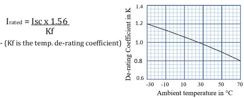
Fig -25: Inverter cubicle a) without andb) with isolation Input dc (zonal) fuses within inverter are meant for fast protectionresponsefrom short circuit energy and eventually from fire fed by the PV arrays. The dc input fuseis of gPVtype and are sized based on PV array design. Thumb rule for sizing dc fuse is 1.56 times short circuit current (Isc) and 1.20 times module open circuit voltage (Voc) as safety factors.
Fig -26: Typical de-rating chart for dc string fuses AC side protection in inverter is based manufacturer design, fault level, and local grid code compliance which is accomplished usually with fuse (type aR), switchgear like molded case circuit breaker (MCCB) or Air circuit breaker (ACB). Some design has ac contactors and /or manual isolatorsas well.

Volume: 08 Issue: 05 | May 2021 www.irjet.net p-ISSN: 2395-0072
Table -15: Utilization category of different fuses as per IEC
Utilisation Category Appplication (Characteristic)
gPV
gG
aM
gR
gS
aR
gTr
gM Full range breaking capacity fuse protection of PV modules and cables against the inverse over-currents in the photovoltaic application Full range breaking capacity fuse for general application, mainly used for cable and line protection. Partial range breaking capacity fuse for the short circuit protection of motor circuits. Full range breaking capacity fuse for the protection of semiconductor devices (quicker than gS). Full range breaking capacity fuse for the protection of semiconductor devices for increased line utilisation. Combines gR and gG performance. Partial range breaking capacity fuse for the short circuit protection of semiconductor devices. Full range breaking capacity fuse for transformer protection, rated in transformer apparent power (kVA) instead of rated current (A). Full range breaking capacity fuse for motor circuit protection, dual rated (widely used in the UK, Australia and South Africa.
gN
North American general application fuse, mainly for cable and line protection. gD North American general application time-delay fuse, mainly for motor circuit protection. Note: The 1st lower-case letter indicates the breaking range of fuse i.e 'g' = full-range and 'a' = partial-range breaking capacity. The 2nd, upper-case letter indicates the characteristic.
9.2 Surge Voltage Protection
Lightning arrestors and surge protection devices are essential to safeguard critical and expensive equipments in solar PV plants as most of equipment like PV modules, inverter, transformer, power cables etc. are exposed to open sky, and hence prone to get damaged due to voltage surge during lightning. Usually,lightning arrestors protectsPV array and high-power upstream evacuation transformers while SPDs protect inverters. SPD connected between line to line and line to ground conductors, routes transient currents to the ground, thus protecting the equipment from damage from over voltage. SPDs can be of metal oxide varistors (MOVs) orgas discharge tubes (GDT) and both has limited lifetime and can handle finite number of surge events. GDT type has high current handling capacity compared toMOV.
Fig -27: AC and DC SPD typesin PV inverter Types of SPDs within inverter are selected based on PV plant engineering i.e.,for direct or indirect lightning strike, sizing of lightning arrestors and earthing system. SPD selection is defined by IEC 61643-12, IEC 62305-4, EN 50539-12:2013. SPD are categorized as Type 1, 2 and 3 based on duration of impulse current handling capacity. IEC 62305-1 and -6 (2006) specify two current impulse waveforms referred as 10/350 ls and 8/20 ls in terms of their rise time and half peak width.
Fig -28: Impulse current waveforms in Type 1 and 2 SPDs


Table -16: Current handling capacity of different SPD types
Type Protection against Current handling capacity
1 Direct lightning strokes 10/350 µs 2 Indirect lightning strokes 8/20 µs 1+2 Direct + Indirect lightning strokes Combination of 10/350µs and 8/20 µs
9.3 Arc Flash
Arc flash is a type of electrical fault that results when electric current flows through an air gap between conductors due to breakdown of an insulating medium causing extreme amounts of light (arc flash). This creates a hazardous condition that vaporize metal, and even destroy equipment, causing significant hazard to anyone in the vicinity. Arching in ac system tend to self-extinguish as the voltage alternates polarity constantly, passing through 0 volts 100 times in 50Hz frequency. While intensity of arc flash in dc is more severe as dc voltage remains at a continuous (zero frequency) and due to presence of discharge energy in dc link capacitors. Three main aspects of system design contribute to the arc fault risk in utility scale PV plant are high dc voltage, current and large geographic distribution of dc wiring. Consequences of an arc flash are fatalities among personnel and damage of equipments. The most common cause of arc faults is insulation failure due to defective or aging material, loose connections, dust, moisture, vermin, and human error such as touchingwrong surface or a tool slipping and touching live conductors. Appropriate creepage and clearance in design plays an important role to avoid arc flash incidents. Dedicated arc flash vent provided in an inverter enclosure and sometimes enclosure doors itself acts as resistance to arc from personal hazards. Hence inverters are not recommended to operate with open doors.ACand DC power cable entry ports are major source of arc flash in outdoor installation, as there are more changes of foreign objects
Volume: 08 Issue: 05 | May 2021 www.irjet.net p-ISSN: 2395-0072
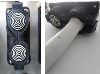
entering through if glands are not sealed appropriately. Use of lead through for cable entering to inverter keeps enclosure IP intact.
Fig -29: Cable lead-throughs (Fimer: PVS 980 inverter) Of many different arc flash energy calculation techniques, the most relying is on voltage, current, radiated energy, or a combination of these. For e.g. consider a 690-volt phase-tophase system with fault current of 20 kA. In absence of any arc protection if, the fault lasts for 200ms. before the overcurrent protection clears it, arc flash energy released is ~3MJ which corresponds roughly to a stick of dynamite and is calculated as per below formula:
Energy = voltage x current x time … Joules i.e.,690V x 20,000A x 0.2 s = 27,60,000 ~3MJ
IEEE 1584-2002 (Guide for Performing Arc Flash Hazard Calculations) provides standard guide for performing arc flash calculations and it also does not exclude the use of alternative calculation methods. Furthermore, NFPA 70E Article 130.3(B)(1) requires an arc flash hazard analysis be performed.
9.4 Ground Fault
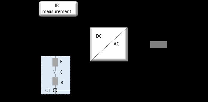
The presence of undetected ground fault can result in arcing and fire in an inverter. The source of ground faults can be within the inverter or in externally connected dcor ac circuit. Based on the grounding system,ground fault is detected by the insulation resistance (IR) and pole grounding circuit incorporated within the inverter. PV system is exposed to potential-induced degradation (PID) effect which is linked mostly to negative potential with respect to ground. This effect is accelerated by high dc voltage, temperatures, and humidity. The phenomenon is not immediately noticeable, rather it develops over time. Grounding the negative dc pole on the inverter mitigates this problem of accelerated performance degradation. Frameless PV module reduces the probability of PID because of no or very less leakage current in absence of metal frame. Frameless modules are with double glass,higher weight, and costsmore, hence not always economical for all projects. In case of ground fault at positive pole or at ac output, inverter detects the fault by measuring flow of leakage current through pole grounding circuit. Inverter interrupt excess current by opening the pole grounding contactor. Fig – 30: Typical IR measurement and pole grounding circuit
Ground fault in floating system or in an ungrounded arrayis detected by measuringinsulation resistance between positive and negative pole with protective earthing (PE). The measuring time is determined by the system leakage capacitancesandinsulation resistance value. PWM based PV inverter, reflects switching frequency to the dc bus, producing leakage currents which in turn flows through the frame and the stray capacitances of PV modules. This formsa resonant circuit with the PV modules, inverter ac filter elements, and grid impedance. Capacitance value depend on weather, PV topology, PWM pattern, metallic frame material, and passive filter element values in an inverter.
As per IEC 62109-2, leakage current is limited to10mA rms per kVA of rated inverter power. Table -17: ground fault detection current as per UL 1741
Inverter DC rating Max. Ground Fault Current
0-25 kW 1 Amp. 25-50 kW 2 Amps. 50-100 kW 3 Amps. 100-250 kW 4 Amps. >250 kW 5 Amps.
According to the IEC 62109-2 safety standard, the IR measurement between the DC and PE is performed before the inverter (IGBT pulsing) is started and pole grounding circuit is off. Pole grounding circuit comes into picture only after IR check is performed. Normally negative pole groundingsystem has both IR and pole grounding current measurement units while floating system has only IR measurement.
10. TESTING
Inverter testing is an exhaustive process. Tests conductedon a product at various stages from design till dispatch and at site to ensure to perform operations as designed. Different types of tests are as listed below. 1. Type Test 2. Routine Test 3. Factory Acceptance Test (FAT) 4. Site Acceptance Test (SAT)
Volume: 08 Issue: 05 | May 2021 www.irjet.net p-ISSN: 2395-0072
10.1 Type Test
Type test also known as compliance test determines if a product complies with and tested for applicable standard relevant to safety, performance, reliability, and grid codes. Type testing essentially means running a design of the product through a series of tests and then future product that is built to the same or very similar design can be considered to comply with the same requirements and if tested in the same way would also pass the test. Listed below are different type tests applicable to utility scale grid tied PV inverters: IEC 62109-1 (2010): Safety of power converters for use in photovoltaic power systems –Part 1: General requirements. This standard covers mainly the following: Temperature limits Electrical ratings Protection against electric shock and fire hazards Protection against fault and short circuit conditions Environmental requirements like pollution degree rating. IEC 62109-2 (2010): Safety of power converters for use in photovoltaic power systems–Part 2: Particular requirements for inverters. This standard covers the array insulation resistance detection for inverters for ungrounded and functionally grounded system. IEC 60068-1: Environmental testing. This test ensures that the product availability is maintained over a long lifetime at specified extreme temperature and humidity variations. Applicable parts covered in this standard are: Part 2-1:2007–Test A: cold Part 2-2:2007–Test B: dry heat Part 2-14: 2009 –Test N: change of temperature Part 2-30: Tests –Test Db: damp heat, cyclic IEC 60529-2004: Degrees of Protection Provided by Enclosures (IP Code). This standard classifies the degrees of protection provided by electrical enclosures basically for the protection of persons against access to hazardous parts, protection of equipment against the ingress of solid foreign objects and the ingress of water. IEC 61000-6-2 (2016): Electromagnetic compatibility (EMC)–Part 6-2: Generic standards –Immunity standard for industrial environments. This standard ensures that the product shall continue to operate normally as intended without degradation of performance due to electromagnetic disturbances generated by external equipment or environment. This standard covers mainly the: Radiated immunity Conducted immunity Electrostatic discharge immunity Surge immunity PFMF (Power Frequency Magnetic Field) immunity EFT (Electrical Fast Transient) immunity IEC 61000-6-4 (2006 and 2010): Electromagnetic compatibility (EMC) –Part 6-4: Generic standards–Emission standard for industrial environments. This standard ensures that the disturbance generated by product operating normally in industrial locations do not exceed a level that could prevent other equipments in vicinity from operating as intended. This standard cover: Radiated emission Conducted emission
IEC 61683 (1999): Photovoltaic systems – Power conditioners–Procedure for measuring efficiency. Purpose of this standard is to provide the means to evaluate the efficiency of solar inverter by a direct measurement of input and output power during factory testing. Measurements includes Euro, CEC,and Max. efficiencies. It also measures no load and standby losses, ripple and distortions in inverter input and output voltage and currents. EN 50530-2010: Overall efficiency of grid connected photovoltaic inverters. This European standard provides a procedure for the measurement of the static and dynamic efficiencies of the maximum power point tracking (MPPT) of grid-connected PV inverters. Based on the static MPPT efficiency and conversion efficiency, the overall inverter efficiency is calculated, and dynamic MPPT efficiency is indicated separately. IEC 62116 (2014): Utility-interconnected photovoltaic inverters –Test procedure of islanding prevention measures. The standard ensures that the inverter in operation and synchronized to grid, should isolate from grid within 2s during loss of grid voltage and frequency. Islanding is a scenario in which agrid tied inverter continues to feed power even though electrical grid power is no longer present which can be dangerous to utility workers. Bureau of Indian Standards (BIS): To ensure quality of solar PV equipment like modules, inverter, and batteries, MNRE has issued guidelines titled ‘Solar Photovoltaics Systems, Devices and Component Goods Order 2017’. PV inverterstoregister with the BIS for following tests: IS 16221 (Part 1): 2016 -Safety of power converters for use in PV power systems - general requirements. IEC equivalent for this standard is IEC 62109-1 IS 16221 (Part 2): 2015 -Safety of power converters for use in solar PV power systems –Particular requirements for inverters. IEC equivalent for this standard is
IEC 62109-2.
IS 16169: 2014 - Test procedure of islanding prevention measures for utility interconnected PV inverters. IEC equivalent for this standard is IEC 62116:2008. BDEW-2008 (Germany specific): Guideline for generating plants connected to the medium-voltage network. CEA-2019 (India specific): Central Electricity Authority (Technical Standards for Connectivity to the Grid) Regulations, 2019. IEEE 1547-2003 (UL specific):Standard for Interconnecting Distributed Resources with Electric Power Systems UL 1741 -2010: (UL specific): Standard for safety for of inverters, converters, controllers, and interconnection system equipment for use with distributed energy resources. Safety includes anti-islanding requirement.
Volume: 08 Issue: 05 | May 2021 www.irjet.net p-ISSN: 2395-0072
IEC 61727 (2004): Photovoltaic (PV) systems –Characteristics of the utility interface.
Following are protections normally included in the above grid codes:
o Abnormal voltage and frequency (OV, UV, OF, UF) o Low and high voltage ride though (LVRT) o High voltage ride though (HVRT) o Anti-islanding protection o Voltage regulation o Frequency droop o Harmonics (THDi and THDv) o DC current injection o Reconnection delay time o Ramp time o Flicker
10.2 Routine Test
Routine tests are performed at the manufacturers’ works place to reveal if any faults in material or construction on each individual product manufactured. This ensures that the product manufactured is in accordance with the proto build on which the type tests have been passed. Manufacturer declares successful completion of the routine test on producing routinetest certificate (RTC). This test does not confirm the reliability of the product.
10.3 FAT (Factory Acceptance Test)
This test is performed at factory and witnessed by customer or customer nominated third-party inspector (TPI). The FAT verifies the equipment is built and operates in accordance with the agreed design specifications documents like GTP (Guaranteed Technical Particular) and MQP. Tests covered during FAT as per MQP includes material quality, characteristics, stage inspection and manufacturing process, routine tests, packing material and process, review of documentation like type and routine test reports of the product and itscomponents including bought out items.
10.4 Site Acceptance Test (SAT)
The tests which are not feasible to perform during FAT at factory, are performed at site and those are mostly related to inverterwhen connected to Point of Common Coupling (PCC). And this includes tests like active power controllability and reactive power control modes: voltage control, reactive power control and power factor control. Below is the list and details of testswhich are part of type, routine and /or FAT. Safety Test To comply to safety standards, the product must pass safety tests such as the high voltage(HV), insulation resistance (IR), and earth bonding test.Ambient temperature and humidity influence the insulation resistance, so HV and IR test readings are unreliable if taken at different temperatures.Thumb rule is that for every 10°C temperature rise, halves the resistance. Earth (or ground) bonding test ensures all thegroundpoints in a product undertestare well connected between each other, and to the mainsground so that the product does not cause an electric shock from insulation failure. As per UL 62109-1 the impedance measured between ground and touch point ≤1mΩ when applied testcurrent is 10 A for ≥2s. Insulation resistance (IR) test ensures effectiveness of insulation between mutual circuits and ground. High voltage (HV) test also called as dielectric voltage or voltage withstand testensures leakage current is less than the specified limit whenthe applied HVfor a duration of 1s to the device under test. As per IEC 62109-1, the test voltage in 1500V system is calculated as 2700V by below relation:
Vtest= {1200+(system voltage)} :- interpolation permitted.
Functional test This test is performed at low (auxiliary or control) voltage level. It includes operation and feedback of auxiliary and control circuits like fans, heaters, lamps, contactors. It also includes protection logicto check inverter response during critical faults and warnings. The faults are normally simulated bychanging threshold parameters in firmware. Nominal Power Test This test is performed to ensure the inverter under test operates at rated output power and current under application of applied nominal voltage and the measured values complies to the product technical specifications. Normally amanufacturer has inverter as DUT (device under test) and dc source connected in back-to-backconfiguration. The ac output of the inverter is fed back into the dc source, allowing power recycling and the power system to supply only the losses relevant to transformer, dc source, DUT and interconnecting cable. The dc source emulates PV array for dc power variations i.e. dc voltage due to temperature variation and dc current during irradiations changes.

Fig -31: Back-to-backtesting of inverter under test Calibration test
This test confirms that the inverter parameters like voltage, currentand power measured by inbuilt inverter controller is within acceptable limits when measured with external (calibrated) measuring instrument like power analyzer. Fig.- 18: Instrument accuracy limits as per IECEE OD-5014, Edition 1.1 2019-06
Parameters Range Accuracy limits
Voltage ≤1000V ≤1kHz ±1.5% Voltage ≤1000V ≥1kHz ≤ 5kHz ±2% Voltage >1000V Dc ≤20kHz ±3%
Volume: 08 Issue: 05 | May 2021 www.irjet.net p-ISSN: 2395-0072
Current >5A Dc ≤60kHz ±1.5% Power Factor 50/60Hz ±0.05 Frequency <10kHz ±0.2%
The IEC 61000-4-30 Class A standard defines the measurement methods, time aggregation, accuracy, and evaluation, for each power quality parameter to obtain reliable, repeatable,and comparable results.IEC 6100-4-30 Class A standardizes the measurements of voltage and current magnitudes, power frequency, Flicker, current and voltage harmonics. Transducers used within inverter like CT and PT accurately measures the electrical power, while temperature sensors like PT100 decides thermal performance and protection from over-temperature. The important factors in selecting the transducers are - Accuracy: closeness of measured to standardvalue - Linearity: measurements consistency over the range - Response time: how fast measurement is performed
Sleep and wakeup mode test This test checks at what minimum input dc voltage and power level inverter goes to sleep mode (i.e. stops generating power simulating night or non-sunshine scenario) and wakes up from sleep mode to fed power to grid. Minimum MPPT voltage specified in product specification is calculated as: (√2*Vrms) +Vd+ Vm ] …. volts Where Vrms is grid voltage, Vdis voltage drop across output LCL filter and across semiconductor devices in power module and Vm is modulation index usually ≤1. Wake up voltage is normally >120% of min. MPPT voltage. In sleep mode, if dc voltage is equal to wake up voltage, the inverter starts generating the power based on dc power availability after a pre-defined delay time which is programable and is normally around5min. Burn-In (Heat Run) Test Purpose of this test is to ensure that temperatures rise of critical components within inverter like IGBTs, filter chokes, mains busbar, fuses, controller, and electronics boards are within the safe limit. Thetest is performed normally for 8 hrs. or till temperature stabilization subject to manufacturer test facility. This test also ensures that power connection such as the bolted joints are appropriately torqued during the manufacturing. Manufacturers burn-tests every inverter that rolls off their line as per their standard process or as request from customer during production or on offered units during FAT. This test detects weak link in an inverter that may not exhibit symptoms during early stage of operation. By exposing these weak points in thefactory, the site issues can be proactively addressed. Harmonics and DC current Injection Measurement PWM topology, switching frequency, modulation index and output LCL filter design ensure that inverter limits the current and voltage harmonic generationto comply specific grid codes.
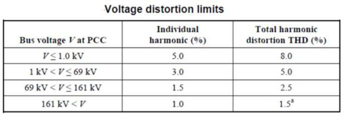
Table -19: IEEE 519-2014 limits for Voltage and current THD
DC current or zero frequency component injected by inverter into transformer winding causes magnetic saturation increasing losses within transformer due to temperature rise.
Table-20: Grid codes for dccurrentinjection limits.
Standard DC Current Injection Limits
IEEE 1547/CEA 2019 0.5 % of rated output current
IEC 61727 1% of rated output current

IEEE P2800 is a draft (expected publication Q2-2021) standard for interconnection and Interoperability of inverterbased resources (IBR) interconnecting with transmission network.The scope of this standardis to develop technical minimum capability and performancerequirements for IBRs including IBRs’ ride-through capability, reactive power (voltage) control, active power (frequency) control, power quality, protectionetc. Inverter Response for Abnormal Grid In case of grid abnormality, inverter responses accordingly to grid codes as setin firmware parameters. Inverter response may be instantaneousordelayed trip, output powerderating or reactive compensation support. Abnormal grid includes under and over voltage, under and over frequency, phase loss, unbalance etc. Local utility specifies disconnection time or how inverter should behave during the grid abnormality. Table-21: Grid codes for abnormalvoltage and frequency
IEC 61727
Voltage Range in % Disconnection time in sec.
< 50% 0.10 50% to 85% 2.00 85% to 110% Continue Operation 110% to 135% 2.00 >135% 0.05
IEEE 1547
Voltage Range in % Disconnection time in sec.
Volume: 08 Issue: 05 | May 2021 www.irjet.net p-ISSN: 2395-0072
< 50%
0.16 50% to 88% 2.00 88% to 110% Continue Operation 110% to 120% 1.0 >120% 0.16
BDEW-2008 Frequency in Hz. Disconnection / clearance time
47.5 to 51.2 Continuous operation (no trip) < 47.5 Instantaneous trip within 0.2s > 51.5
IEEE 1547 Frequency in Hz. Disconnection / clearance time
> 60.5 Instantaneous trip within 0.16s <59.8 to 57.0 Adj. Inst.trip within 0.16 -300s <57.0 Instantaneous trip within 0.16s
CEA -2019 Frequency in Hz. Inverter operation
47.5 to 52 Continuous operation (no trip) 49.5 to 50.5 Operation at rated output power
Grid Shutdown and Reconnection Delay The grid shutdown test ensures that the inverter in operation and synchronized to grid, gets isolated from grid within specified time (which is normally <2s) during loss of grid voltage and frequency. This test also ensures that inverter does not produce high voltage spikes (i.e.,> √2 times of nominal grid voltage) when it disconnects from the grid. The time required for inverter to reconnect once the gird resumes back is called the reconnection time and istypically ≥60s. IEEE 1547 specifies a reconnection delay adjustable up to five minutes (300s).
Voltage Regulation This test checks how inverter compensates grid over or under voltage by feeding inductive or capacitive reactive current respectively into the grid as specified by appropriate grid code. The ratio of additional reactive current (∆I) requirement to support change in voltage (∆V) is given by ‘Kfactor, which is normally 2 or more.

Fig -32: Reactive current injection during voltage regulation Short time grid disturbances due to voltage sags or swells cause cascading tripping when demand is more than generation. To avoid this, grid codes mandate dynamic voltage support in terms of Low Voltage Ride-Through (LVRT) and High Voltage Ride-Through (HVRT) capabilities in inverter. This capability keeps inverter connected to the grid and support voltage through reactive power injection.
Fig -33: LVRT and HVRT curve as per CEA-2019
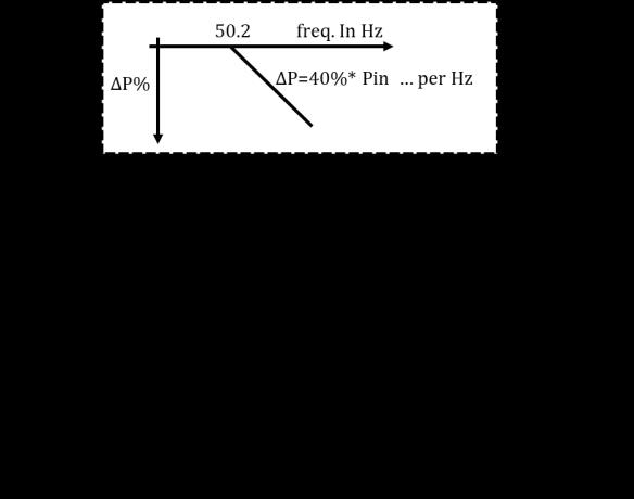
Frequency Droop This test checks how inverter compensates grid over frequency by reducing its active output power feeding to grid as specified by appropriate grid code.
Fig -34: Frequency droop curveas per BDEW Ramp Test This test checks inverter’sactive power ramp specific to grid codeduring startup and shutdown. The PCCcontrols plant ramp rate set by utility operatoras per grid code which is important from grid stability. Voltage (Phase) Imbalance Voltage unbalance is a condition in which the three-phase voltages differ in amplitude or displace from 120° phase relationship, orboth. The degree of unbalance is defined by the ratio of the negative sequence voltage component to the positive sequence component. According to the EN 50160:2010 and the IEC 61000-2-2 standards, the voltage unbalance, or the negative phasesequence component of the supply voltage shall be within the range of 0 to 2% of the positive phase sequence component.

Volume: 08 Issue: 05 | May 2021 www.irjet.net p-ISSN: 2395-0072
During un-balanced fault like line-to-line fault, inverter responds to sudden increase in negative sequence voltage by injecting fastnegative sequence current output to improve phase symmetry. Flicker
Fluctuation in inverter output voltage is a result of variations in solar irradiance caused by the movement of clouds which creates voltage flicker that distorts nominal voltage waveform of utility network. Magnitude of flicker not only depends on inverter output at PCC (point of common coupling) but also on the stiffness of the grid, which is function of voltage level, cable distance from the substation, substation transformer ratings and plant electrical design. Parameters considered in grid code are the short-term flicker severity (PST) and long-term flicker severity (PLT). PST is measured in per units over a 10-minute period and the PLT is measured in per units over a 2-hour period. As per IEC 61727, the PST and PLT values should notexceed the limits stated in the relevant sections of IEC 61000-3-5 for LV systems andforcurrent ≥ 16 A.
Flicker measuredin power analyzer is as per IEC61400-4-15 and limits as specified inIEC61000-3-5 is as tabulated below.
Short-term (10 min) flicker emission limit: PST ≤ 1 Long-term (2 hrs.) flicker emission limit: PLT ≤ 0.65
MPPT Efficiency Test In case of PV inverter both the conversion and MPPT efficiencies contributes the pay-back time and the profitability of grid-connected PV systems. The behavior and efficiency of the MPPT can be analyzed in both static and dynamic conditions. The static MPPT efficiency describes the ability of the MPPT to find and hold the MPP under constant environmental conditions (i.e., solar irradiance and celltemperature) whereas the dynamic MPPT efficiency describes the ability in tracking the MPP in case of variable conditions.
In dynamic conditions the MPP and hence its efficiency is normally analyzed using staircase or trapezoidal irradiance profile. Slow MPP tracking reduces the MPP efficiency.


Fig -35:Dynamic MPPT testing with trapezoidal irradiance profile Communication Check
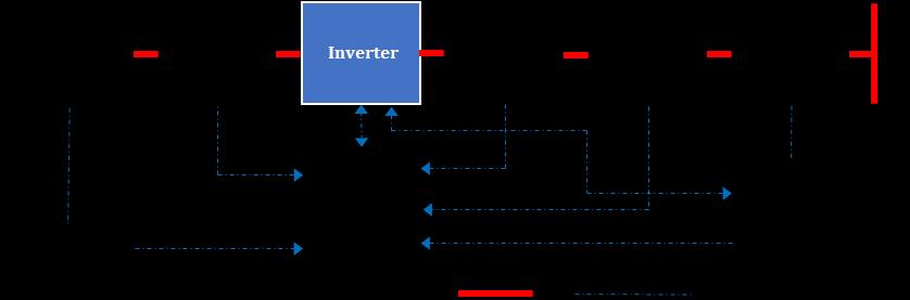
Establishing communication and checking exchange of signals like commands, references and setpoints between inverter and external customer controller like PPC, SCADA is performedduring a FAT.
Fig -36:Inverter communication with AC and DC BOS In most cases, even in absence of hardware controller, the test is performed with ModScan simulator. ModScan operates as a Modbus master and allows to access and change data points in a connected slave device using the RTU mode.
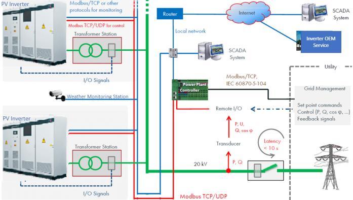
Fig -37: Typical communication protocols in a PV plant
11. Participants of PPA and Their Role in PV Solar Plant
Generating companies (GENCOs) invites tenders for setting up PV plants where interested developers' bids. GENCO signs a Power Purchase Agreement (PPA)with the developers, and then a Power sale Agreement (PSA) with the distributor companies (DISCOM)to sell the power to the consumers. PPA is a financial agreement made between power producer and customer power purchaser.
Fig -38: Participants of PPAand their role in PVplant Federal power generators (GENCOs)in India are: - NTPC(National Thermal Power Corporation Limited)

Volume: 08 Issue: 05 | May 2021 www.irjet.net p-ISSN: 2395-0072
- NLC(Neyveli Lignite Corporation Limited) - NHPC(National Hydroelectric Power Corporation) - THDC(Tehri Hydro Development Corporation Limited) - NEEPCO(North East Electric & Power Corporation Ltd.) - SJVNL(Satluj Jal Vidyut Nigam Ltd.) Federal power transmitter in India is Power Grid
Corporation of India Ltd. (PGCL). PGCL is a CTU (Central
Transmission Utility) engages in power transmission business with the responsibility for planning, implementation, operation, and maintenance of interstate transmission system (ISTS). Independent Power Producers(IPPs) are private entities or developers whoown and or operate plant to generate electricity and sell it to a utility. Reputed Indian IPPs are
Tata Power, ReNew Power, Adani etc. Power Distributor companies (DISCOMs) participates in transmission and distribution of power. (SECI) is a Central Public Sector Undertaking (CPSU) company under the administrative control of the MNRE, to facilitate the implementation of national solar mission into solar project development on turnkey basis for several PSUs.
CEA specifies technical guidelines for building the solar plant and CERC (Central Electricity Regulatory
Commission) regulates electricity traffic of GENCO. Load Dispatch Centre(LDC): Operation of each of regional grids is handled by the regional load dispatch centers (RLDC). The state grids are managed and operated by state load dispatch center (SLDC). National Load Dispatch
Centre (NLDC) schedules and dispatch electricity across various regions and also coordinates cross-border energy exchanges. Electricity Regulatory Commission (ERC): Tariff regulation and grant of connectivity is governed by regulations issued by the Central Electricity Regulatory
Commission (CERC)and the respectiveStateElectricity
Regulatory Commission (SERC).
12. CONCLUSIONS
Globally utility scale solar PV installation is growing at exponential rate and at a same time record-low power purchase agreement (PPA) tariff is intensifying scrutiny of project budgets. This isforcingPV invertermanufacturer for price cuts andtakeconservative call ondesign cost versus product life. This tradeoff impacts design, manufacturing quality and in turn on-site performance of the product. Considering the ongoing site issues in inverter, it is important for customer to emphasis on product design factors like performance reliability safety factors.
ABBREVIATIONS
o ASTM -American Society for Testing and Materials. o CISPR - Comité International Spécial des Perturbations
Radio, (The International Special Committee for Radio
Protection) o CSA -Canadian Standards Association o IEC -The International Electrotechnical Commission o IEEE -Institute of Electrical and Electronics Engineers. o NEMA -The National Electrical Manufacturers Association o TUV- Technischer Überwachungsverein (Technical
Inspection Association)
REFERENCES
(1) National Renewable Energy Laboratory: Q4 2019/Q1 2020 Solar Industry Update by David Feldman, Robert
Margolis, May 28, 2020. (2) Availability factor of a PV power plant: evaluation based on generation and inverter running periods, by
Nallapaneni Manoj Kumar, Srikar Dasari Jagathpally
Bhagwan Reddyc. International Scientific Conference
“Environmental and Climate Technologies”, CONECT 2018.
(3) Photovoltaic Inverter Reliability Assessment. Adarsh
Nagarajan, Ramanathan Thiagarajan, Ingrid Repins, and
Peter Hacke National Renewable Energy Laboratory,
Technical Report NREL/TP-5D00-74462 October2019 (4) Aiming for grid parity on utility-scale solar applications
Industry Application IA08303004E Effective September 2012. (5) An Overview of Grid Codes and Power Quality in Utility
Connected Solar PV Power Plants, by Kiran Dhandale,
Dr. Bhaskar, International Journal for Research in
Applied Science & Engineering Technology, Volume 8
Issue IV Apr 2020. (6) Active and Reactive Power Strategies with PeakCurrent
Limitation for Distributed GenerationInverters During
Unbalanced Grid Faults, By Antonio Camacho, Miguel
Castilla, Jaume Miret, Angel Borrell and Luis Garc´a de
Vicu˜a, IEEE Transactions on industrial electronics, 2014. (7) Research on Inverter Integrated Reactive Power Control
Strategy in the Grid-Connected PV Systems, by Hua Li,
Che Wen, Kuei-Hsiang Chao, and Ling-Ling Li. Energies 2017, 10, 912; doi:10.3390/en10070912.