3 minute read
Pricing (value for money

from IRJET- A Review of Design, Manufacturing of Grid Tied PV Inverter and its Impact on Site Performance

Volume: 08 Issue: 05 | May 2021 www.irjet.net p-ISSN: 2395-0072
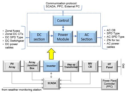
comply like communication type to interface with external controller and number of dc fusesbased on array size etc.
Advertisement
Fig -14: Inverter interface to AC and DC BOS
4.3.1 Inverter AC Output Interface
Inverter Transformer
To step up inverter output voltage and sync with the grid voltage level, the transformer usedare commonly called as “Inverter duty transformer” (IDT) or LV/MV transformer. Based on selected inverter model, the key parameters to be considered for the selection of inverter transformers are:
o Nominal power rating (with continuous and overloading) o LV voltage level and frequency o Voltage rise withstands -dv/dt (typically <1kV/μs) o THDi harmonics pattern including dc current o Minimum Isc impedance (typically ≥6%) o Voltage withstand level wrt ground o Winding connection (star /delta) and vector groups for e.g., Dy11d0 or Dy11y11 in case of three winding transformer. Normally star point of LV side is recommended to be floating inIT grounding system. Inverter duty (LV/MV) transformer provides galvanic isolation between the PV array and the utility grid by breaking ground loops. Besides, it guarantees no DC current is injected into the grid else there exist a common-mode voltage which generates common-mode currents, which produces electromagnetic interferences, and grid current distortion. Vector sum of all three voltage in 3-phase supply should be zero which is possible in pure sine waveforms. This is not the case in PWM based inverter asits output voltage swings rapidly with switching frequency creating source of common mode voltage. In a 3-phase transformer the primary and secondary windings are connected in different combination of star (Y), delta (∆) and zig zag to mitigate harmonics. Delta winding in transformer reduces third order harmonics. Vector group indicates phase displacement expressed as the clock hour number.For e.g.,Dyn11 transformerhasdelta (∆) connected primary and a star (Y)connected secondary winding with star point (n) brought out. In Dyn11, theLV lead HV by phase shift of 30 deg (11° clock).
Table -11: Transformer vector group types
Degree Phase relation Connection Degree Phase relation Connection
0° In phase Yy0, Dd0 180 Lag(180°) Yy6, Dd6 30° Lag(30°) Yd1, Dy1 150 Lead150°) Yd7, Dy7 60 Lag(-60°) Dd2 120 Lead 50°) Dd8 120 Lag(-20°) Dd4 60 Lead (60°) Dd10 150 Lag(150°) Yd5, Dy5 30 Lead (30°) Yd11, Dy11
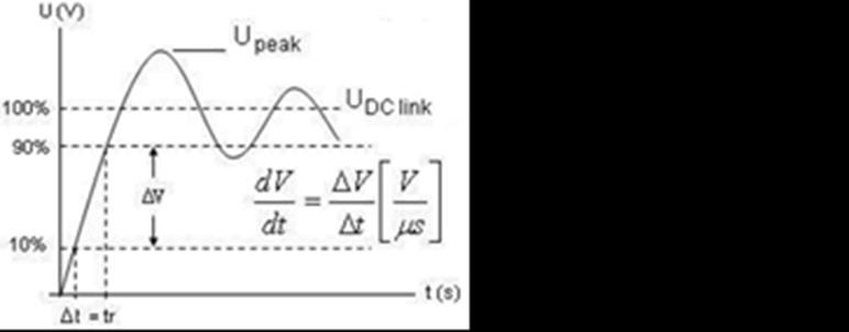
Voltage spikes (dv/dt) generated by PWM based inverter results very high voltages leads to insulation damage in cables and winding in transformers. It also contributes to conducted EMI. Inverter output (LCL) filter reduces the dv/dt to acceptable limits to ~1kV per μsin LV system
Fig -15: Typical dv/dt curve As a general rule, the voltagespike due to rate of change of voltage (dv/dt) is twice the DC bus voltage. i.e.,in 690Vrms, the max voltage spike is calculated as 690*√2*2=1952V. AC interface equipments like inverter output cables, AC circuit breakers, transformers are rated to handle this higher voltage else this voltage level reduces service life for the equipment.
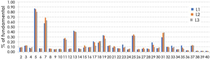
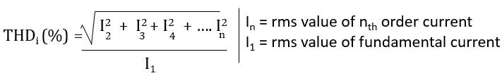
Fig -16: Typical inverter current harmonics (THDi) pattern Total current harmonic distortion (THDi) is given by:
RMS current for sizing cables and transformer is given by:
AC Output connections The ac output interface of inverter toLV/MV transformer can be either through cable or bus duct, depending on current rating and inverterdesign. Factors to be looked for inverter output interface are, conductor type Al or Cu, its size in sq.mm, no. of runs per phase, cable insulation level (1.8/3.0 kV in 1500V and 1.1kV in 1000V dc system) and appropriate gland plates for ac cable entry from inverter transformer.