3 minute read
Manufacturing Process: MQP, QAP

from IRJET- A Review of Design, Manufacturing of Grid Tied PV Inverter and its Impact on Site Performance

Volume: 08 Issue: 05 | May 2021 www.irjet.net p-ISSN: 2395-0072
secondaries are also available. With inverter now being developed with high power capacities like e.g., 3.125MW, 5MW etc., the transformer MVA and hence power block ratings are increasing even with reduced number of inverters and number of transformer secondary windings.
Advertisement
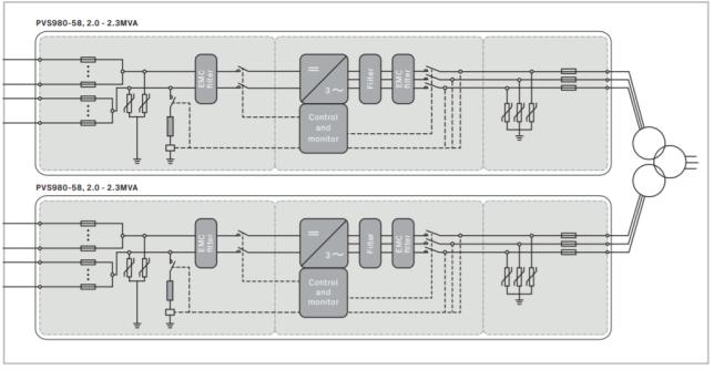
a) Single line diagram
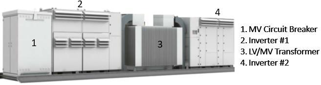
b) Equipment details
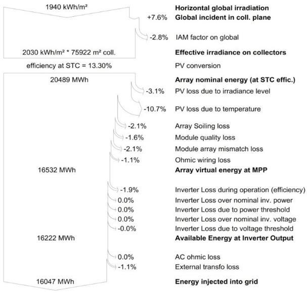
Fig -9: a) and b) Skid solution power block with two inverters (Reference: FIMER compact skid solution) PV-Syst is the most popular and commonly used simulation software estimates the performance of the solar power plant in terms of AEP (annual energy production in kWH) and performance ratio (PRin %) representing losses at various stages of plant. The software uses .PAN file as model for PV module, and .OND file as an inverter model. PVsystrepresents the loss contributed by an inverter are as tabulated below: Inverter loss during operation (efficiency) is inverter’s
DC to AC conversion efficiency, weighted for variance in power levels. Inverter loss over nominal inverter power is power clipping in overloading where the array produces more dc power than the maximum acoutput of the inverter. Inverter loss due to power threshold is the loss of energy when the array operates below the inverter minimum power threshold. Inverter loss over nominal inverter voltage is the energy loss when the array is producing voltage below the inverter MPP voltage range. Inverter loss due to voltage threshold isthe energy loss when the array is producing voltage above the inverter
MPP voltage range. AC and dc ohmic wiring loss is the voltage drop due to wiring resistance and is calculated as one value for the whole system. The value is based on plant design including contribution from inverter power block size. The Maximum Power Point Tracking (MPPT) range or window of an inverter decides how long the inverter stays connected during the day. Wider the MPPT range in an inverter, the higher the energy harvest. Higher inverter ac output voltage reduces MPPT window thus impacting energy harvest and is represented as voltage threshold loss. An .OND (One Note Database) file contains specifications of an inverter used in the PVsyst simulation. OND file acting an inverter model in PVSyst is normally certified by third party agencies like TUV, DNV etc. to confirm the accuracy especially the efficiency, deratings with respect to data sheet parameters and type test reports.
Table -4: Typical PVSyst loss analysis in 10MW PV plant
To study impact on power system caused by PV system and by grid on solar inverter in utility scale PV plant, otherforms of PV solar inverter model are used in simulation software like PSSE (Power System Simulator for Engineering), PowerFactory from DIgSILENT, PSCAD (Power System Computer Aided Design).
b) Inverter Features
In addition to basic features in an inverter, extrafeatures (as listed below) sold by manufacturer as an optional depends upon customer requirements and compliance. Number of dc inputs -With or without dc fuse (zonalor string) protection -With or without dc current (zonalor string) monitoring Auxiliary power supply (external or inbuilt) Night VAR compensation feature (some make,andmodels has this feature as default) Surge protection type: type 2 or type 1+2 Type of dc input and ac output switchgear protection type like ACB, MCCB, manual /electric operated isolator etc. Type of interface to LV/MV transformer: Busbar or cable connection Type of communication: Inverter interface with external controller like SCADA, PPC etc.