2 minute read
Reliability, availability, and maintenance (RAM) analysis

from IRJET- A Review of Design, Manufacturing of Grid Tied PV Inverter and its Impact on Site Performance

Volume: 08 Issue: 05 | May 2021 www.irjet.net p-ISSN: 2395-0072
Customer IOs (digital, analogue) types: For Inverter to interface with external customer equipment like LV/MV transformer, MV circuit breaker etc. Low temperature (cold weather) option (< -20°C) High altitude operation (>2000m altitude) Inverter short circuit current (Isc) is limited by percentage impedance (z%) of inverter and is mostly decided by inductance value of output filter. Based on design inverter models may have one inductance (in LC filter) or two inductances (in LCL filter). Some inverter manufacturer (if their design permits) considers trade-off in passing on extra percentage of this impedance into LV/MV transformer scope or to include in inverter scope with additional cost. For a line inductance in output filter, operating voltage,and frequency of 74μH, 690V and 50 Hz. respectively, then as per below relation, the z% and Isc calculated is 5% and 17kA respectively. Isc = Irated / Z% Z% = √3 * I * XL (Where XL = 2*π*F*L)
Advertisement
c) Product Design and Technology i) DC input voltage: 1000V verses 1500V DC
The maximum dc voltage in IEC standard for LV equipment is 1500V. DC voltage of solar inverter has increased from 1000 to 1500 volts in order to achieve higher power rating with lower system costas higher system voltage reduces number of arrays, its associated cables, combiner boxes. Higher the system voltage also contributes to reduced I2R loss in cables. Major challenges in high voltage product design are maintaining insulation levels, creepages and clearances. Table -5: Comparison of current per kW in 1000V and 1500V DC inverter products
Nominal AC Output Power -kW 1000
Max. Input DC Voltage -Volts 1000 1500 MinMPPT Voltage -Volts 605 980 Max. DC Current -Amps 1653 1020 Nominal AC current -Amps 1443 875 Nominal AC Voltage -Volts 400 660 DC Current per kWac -A/kWac 1.65 1.02 AC Current per kWac -A/kWac 1.44 0.87
Sooner rather than later, 1500Vdc system can be a history and the benchmark could hit 2000Vdc technology, but, regulation and product certification may delay the adoption of thisnext technological phase.
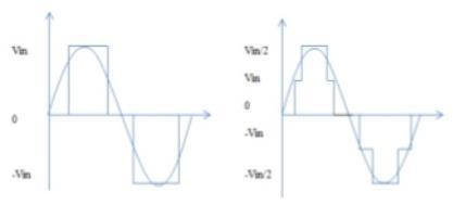
ii) Inverter Bridge Topology – Three level vs Two level
Multi-level PWM topology like three level is an efficient technology in PV inverter applications, which improves quality of output voltage and current. Normally topology used in 1000V and 1500V dc inverter is two level (2L) and three level (3L) respectively. Compared to conventional two-level, the three-level topology has following advantages: reduced losses in magnetics contributing to increased efficiency reduced stress on IGBT switches reduced output harmonics distortion and hence the size of the magnetic componentslike inductor chokes lower dv/dt of output voltage and thus less stress on output cables and LV/MV transformer windings
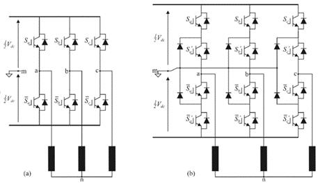
Fig -10: Two level and three level (NPC) based topology Advanced version of 3L-NPC called active NPC (ANPC) topology is derived by adding an active switch in anti-parallel to each clamping diode. This topology performs superior to NPC in providing more zero switching states to evenly distribute IGBT losses and maintain junction temperatures.
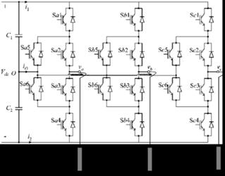
Fig -11: Three level (3L) Active NPC (ANPC) based topology
iii)Component Design Margins
For long term reliable operation and 25 years of useful life critical components of inverter like IGBTs, capacitors, cooling fans etc. are selected with enough design margin when subjected to extreme operational conditions. Design margin in critical components minimizes inverter failure rates,