International Research Journal of Engineering and Technology (IRJET)
e-ISSN: 2395-0056
Volume: 08 Issue: 05 | May 2021
p-ISSN: 2395-0072
www.irjet.net
Anti-Ackermann Steering System of Formula Student car Advait Deshmukh*, Gouri Tawhare*, Shreyash Kochat* *Student,
Department of Mechanical Engineering, Vishwakarma Institute of Information Technology, Pune-48, Maharashtra, India ---------------------------------------------------------------------***---------------------------------------------------------------------
Abstract - In present study, as a basic step for modeling
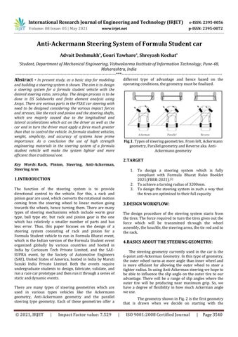
different type of advantage and hence based on the operating conditions, the geometry must be finalized.
and building a steering system is shown. The aim is to design a steering system for a formula student vehicle with the desired steering ratio, zero play. The design process is to be done in DS Solidworks and finite element analysis using Ansys. There are various parts in the FSAE car steering with need to be designed considering the various impact forces and stresses, like the rack and pinion and the steering shafts, which are majorly caused due to the longitudinal and lateral accelerations which act on the driver as well as the car and in turn the driver must apply a force much greater than that to control the vehicle. In formula student vehicles, weight, simplicity, and accuracy of systems have prime importance. As a conclusion the use of high strength engineering materials in the steering system of a formula student vehicle will make the system lighter and more efficient than traditional one.
Fig.1. Types of steering geometries. From left, Ackermann geometry, Parallel geometry and Reverse aka. AntiAckermann geometry
2.TARGET
Key Words: Rack, Pinion, Steering, Anti-Ackerman, Steering Arm
1.
1.INTRODUCTION 2. 3.
The function of the steering system is to provide directional control to the vehicle. For this, a rack and pinion gear are used, which converts the rotational motion coming from the steering wheel to linear motion going towards the wheels, hence turning them. There are many types of steering mechanisms which include worm gear type, ball type etc. but rack and pinion gear is the one which has relatively a smaller number of parts and has less error. Thus, this paper focuses on the design of a steering system consisting of rack and pinion for a Formula Student vehicle to run in Formula Bharat event, which is the Indian version of the Formula Student event organized globally by various countries and hosted in India by Curiosum Tech Private Limited, and the SAESUPRA event, by the Society of Automotive Engineers (SAE), United States of America, hosted in India by Maruti Suzuki India Private Limited. Both the events require undergraduate students to design, fabricate, validate, and run a race car prototype and then run it through a series of static and dynamic events.
3.DESIGN WORKFLOW: The design procedure of the steering system starts from the tires. The force required to turn the tires gives out the force which will be transmitted through the wheel assembly, the knuckle, the steering arms, the tie rod and to the rack.
4.BASICS ABOUT THE STEERING GEOMETRY: The steering geometry currently used in the car is the 6-point anti-Ackerman Geometry. In this type of geometry, the outer wheel turns at more angle than inner wheel and is more efficient for allowing the outer wheel to steer a tighter radius. In using Anti-Ackerman steering we hope to be able to influence the slip angle on the outer tire to our advantage. There will be a range of slip angles where the outer tire will be producing near maximum grip. So, we have a degree of flexibility in how much Ackerman angle we use.
There are many types of steering geometries which are used in various types vehicles like the Ackermann geometry, Anti-Ackermann geometry and the parallel steering type geometry. Each of these geometries offer a
© 2021, IRJET
|
Impact Factor value: 7.529
To design a steering system which is fully compliant with Formula Bharat Rules Booklet 2021(FBRB-2021).[1] To achieve a turning radius of 3200mm. To design the steering system in such a way that the tires are optimized to their full capacity
The geometry shown in Fig. 2 is the first geometry that is drawn when we decide on starting with the
|
ISO 9001:2008 Certified Journal
|
Page 3540